In our gaze tracking system, we acquire the Z-distance data using an ultrasonic sensor as well as using the actual inter-distance of two pupil centers obtained during a user calibration stage. Then, we measure the Z-distance of user’s eye from the camera based on the actual inter-distance of two pupil centers during user calibration stage. In the testing stage, our gaze tracking system calculates the difference between the Z-distance of user’s eye when capturing the current image and that obtained during user calibration. If this difference is not greater than a threshold, the user’s head movement does not need to be compensated, and our system calculates the gaze position without compensation. If this difference is greater than a threshold, our system checks whether a case of head rotation (yaw) based on the vertical axis has occurred. If this case has not occurred, our system compensates the user’s head movement and calculates the gaze position. If it has occurred the user’s head movement does not need to be compensated, and our system calculates the gaze position without compensation.
2.1. Gaze Tracking Algorithm
Our gaze tracking algorithm is based on the PCCR method [
7,
21], which is the most commonly used method using 2-D mapping-based approach for gaze tracking. Details of our gaze tracking method are provided below with explanations.
Figure 1.
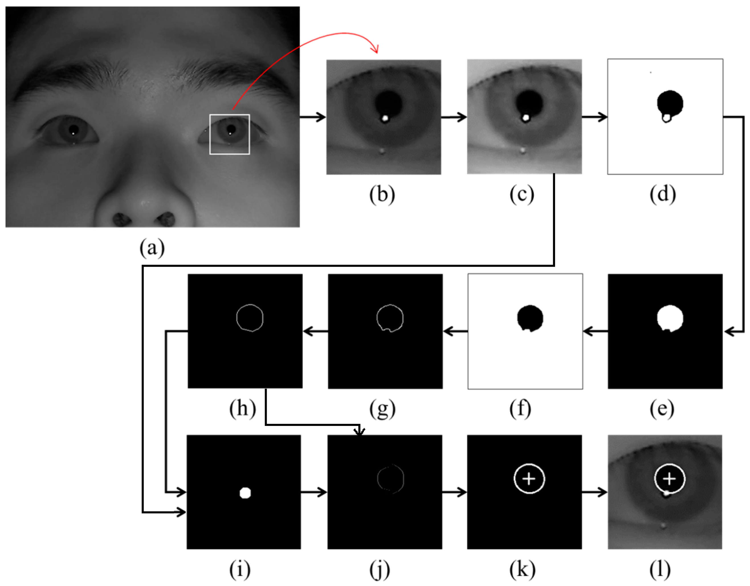
Examples of pupil center and boundary detection: (a) rough position of corneal SR is located in the original image (b) region for detecting pupil area is defined. Result images by (c) histogram stretching, (d) image binarization, (e) morphological operation, (f) component labeling, (g) canny edge detection, (h) convex hull method, (i) image binarization of (c), (j) subtracting the overlapped parts of (h) and (i) from (h), (k) ellipse-fitting method, and (l) final detection result of pupil center and boundary.
Figure 1.
Examples of pupil center and boundary detection: (a) rough position of corneal SR is located in the original image (b) region for detecting pupil area is defined. Result images by (c) histogram stretching, (d) image binarization, (e) morphological operation, (f) component labeling, (g) canny edge detection, (h) convex hull method, (i) image binarization of (c), (j) subtracting the overlapped parts of (h) and (i) from (h), (k) ellipse-fitting method, and (l) final detection result of pupil center and boundary.
As the first step, the rough position of the corneal SR is identified by finding the bright pixels in the captured image. Then, the region for detecting the pupil area is defined based on the identified position of the corneal SR as shown in
Figure 1b. In order to make the pupil boundary more distinctive, histogram stretching is applied to this region (
Figure 1c), and binarized image is obtained because pupil area is usually darker than the surrounding regions as shown in
Figure 1d. Then, only the pupil region is left in the image by excluding the corneal SR and other noise regions through the procedures of morphological operation and component labeling as shown in
Figure 1e,f. Pupil boundary points are located by canny edge detector as shown in
Figure 1g, and the damaged part on the pupil boundary by the corneal SR can be compensated (
Figure 1h) through the convex hull method procedure [
24,
25,
26]. A binarized image of
Figure 1c is obtained as shown in
Figure 1i. Then, the overlapped region of
Figure 1h,i is removed from the image of
Figure 1h as shown in
Figure 1j. With
Figure 1j, sn accurate pupil boundary can be detected by excluding the corneal SR. With the remaining points on the pupil boundary, the accurate pupil boundary is detected by ellipse-fitting method as shown in
Figure 1k. The results of pupil boundary and center detection are shown in
Figure 1l.
When the pupil center and boundary are detected as shown in
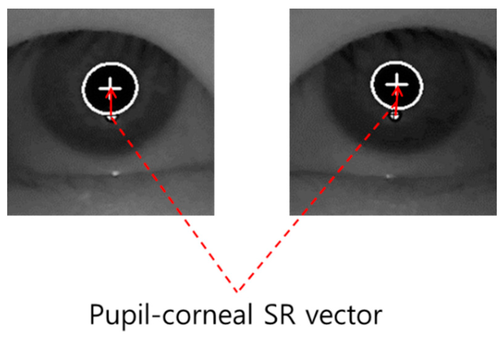
Figure 1l, our gaze detection algorithm defines the searching area for detecting the accurate position of corneal SR. Within this area, the accurate center of corneal SR is detected through the image binarization process and by calculating the geometric center position. Based on the detected centers of pupil and corneal SR, the pupil-corneal SR vector can be obtained as shown in
Figure 2.
Figure 2.
Example of pupil-corneal SR vector.
Figure 2.
Example of pupil-corneal SR vector.
Based on the pupil-corneal SR vector, the user’s gaze position is calculated using a geometric transform method as follows [
7,
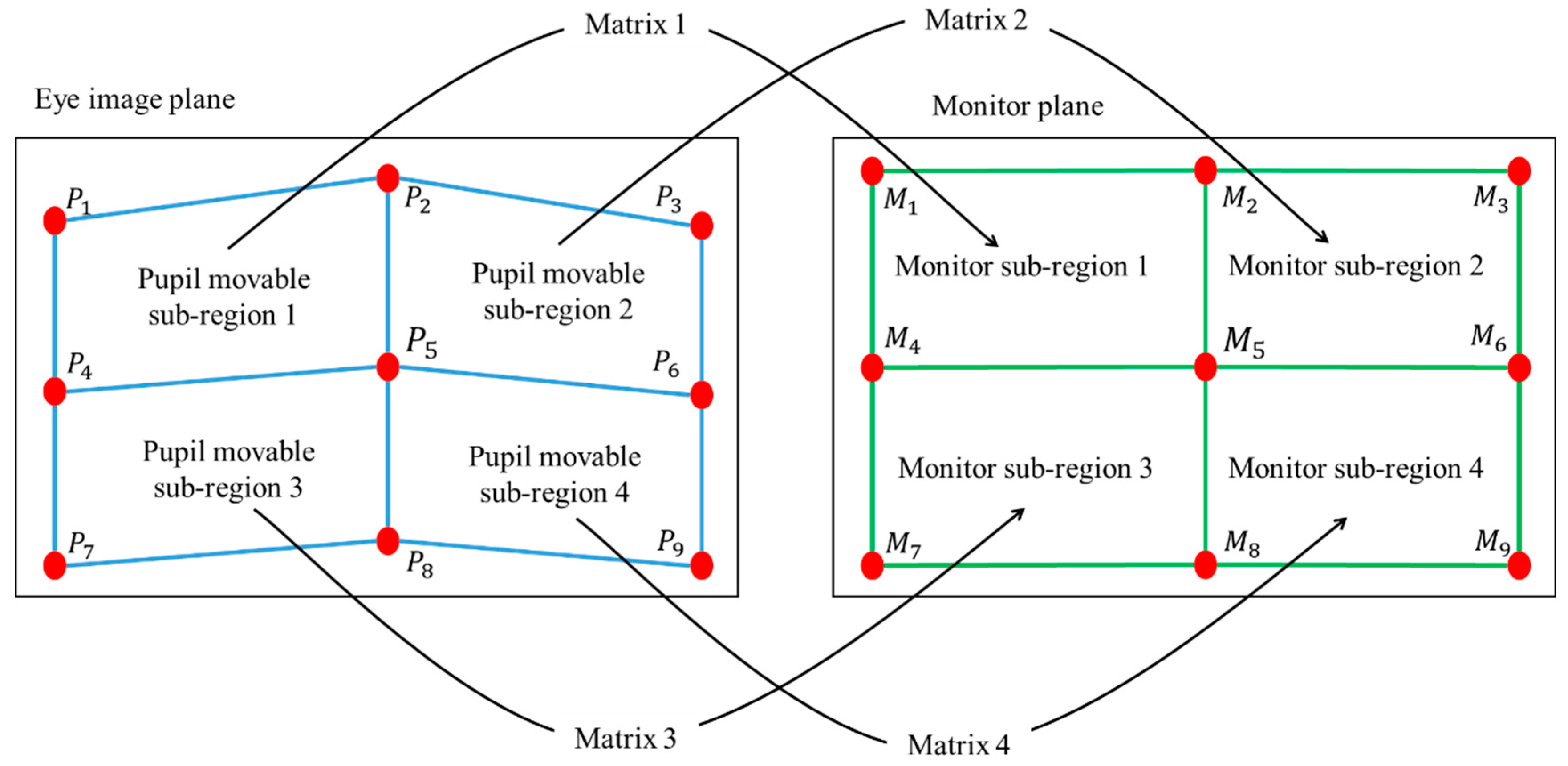
21]. Pupil-corneal SR vector is used for obtaining the mapping relationship between the pupil movable sub-region and monitor sub-region as shown in
Figure 3. In our gaze tracking system, each user should look at nine reference points (
M1,
M2, …
M9 of
Figure 3) on the monitor during the user calibration stage. From that, nine pupil centers in the images are acquired, and nine pupil-corneal SR vectors are consequently obtained. In order to compensate the corneal SR movement caused by the head movement, all the starting positions of nine pupil-corneal SR vectors are superimposed, and the compensated nine pupil centers (
P1,
P2, …
P9 of
Figure 3) in the images are acquired. We include detailed explanations about the procedure for compensating the pupil centers as follows. For example, the positions of the corneal SR and pupil center are assumed to be (120, 120) and (110, 110), respectively, in the first image. In addition, those of the corneal SR and pupil center are assumed to be (105, 134) and (130, 90), respectively, in the second image. Then, the amount of movement between the two corneal SR positions in the first and second images becomes −15 (105−120) and +14 (134−120) on the
x- and
y-axis, respectively. Therefore, if we attempt to set the position of corneal SR in the first image (120, 120) to be the same as that in the second image (105, 134) (the vectors of corneal SR coincide), the position of pupil center position in the first image (110, 110) is changed to be (95, 124) considering the amount of movement (−15, +14). This new position of (95, 124) is the compensated pupil center, which is used for calculating gaze position instead of the original position of pupil center (110, 110).
Then, four pupil movable sub-regions and monitor sub-regions are defined, and a geometric transform matrix that defines each pair of pupil movable sub-regions and monitor sub-regions is obtained as shown in
Figure 3 and Equation (1).
Figure 3.
Relationship between pupil movable sub-regions and monitor sub-regions.
Figure 3.
Relationship between pupil movable sub-regions and monitor sub-regions.
In Equation (1),
n is 1, 2, 4, and 5. The four points of (
P(n+i)x,
P(n+i)y) and (
M(n+i)x,
M(n+i)y) (i is 0, 1, 3, and 4) represent the X and Y positions of compensated pupil center (in eye image) and reference point (on the monitor), respectively. From Equation (1), we can obtain eight unknown parameters (
a, b, c ... h) using matrix inversion:
In general, the shape transform from one quadrangle to the other can be mathematically defined by using several unknown parameters as shown in [
27]. If one quadrangle is changed to the other only by in-plane rotation and translation (x-axis and y-axis), the transform matrix can be defined by using three unknown parameters. If one quadrangle is changed to the other only by in-plane rotation, translation (x-axis and y-axis), and scaling, the transform matrix can be defined by using four unknown parameters. In case that one quadrangle is changed to the other only by in-plane rotation, translation (x-axis and y-axis), scaling, and parallel inclination (x-axis and y-axis), the transform matrix can be defined by using six unknown parameters. In the last case, if one quadrangle is changed to the other by in-plane rotation, translation (x-axis and y-axis), scaling, parallel inclination (x-axis and y-axis), and distortion (x-axis and y-axis), the transform matrix can be defined by using eight unknown parameters [
27]. Because the shape transform from one pupil movable sub-region of
Figure 3 to one monitor sub-region of
Figure 3 can include the various factors of the last case, we define the transform matrix by using eight unknown parameters.
Once we obtain the parameters (
a, b, c ... h), we can calculate where the user is staring at on the monitor (
M’x and
M’y of Equation (2)) using the compensated pupil center in a current frame (
P’x and
P’y Equation (2)):
2.2. Analyses of the Change of Pupil-Corneal SR Vectors According to Head Movements
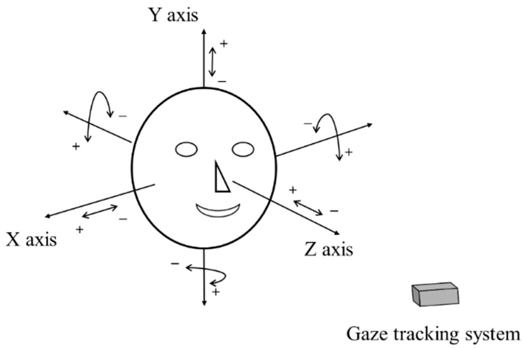
The geometric transform matrix of Equation (2) is obtained at one Z-distance between the user and the screen. Therefore, if the user’s head is moved after the calibration, the matrix is not correct for calculating the gaze position, which increases the consequent gaze detection error. To overcome this problem, we propose the method of compensating user’s head movement using an ultrasonic sensor. Before explaining our compensation method in detail, we define the user’s head movements according to translation and rotation movement based on the X-, Y-, and Z-axes, respectively, in 3D space, as shown in
Figure 4. In addition, we define the symbols representing the head movements in
Table 1.
Figure 4.
Definition of head rotation and translation.
Figure 4.
Definition of head rotation and translation.
Table 1.
Definition of the symbol representing the head movements.
Table 1.
Definition of the symbol representing the head movements.
| Head Movements | X Axis | Y Axis | Z Axis |
|---|
| Translation | T_X{+, –} | T_Y{+, –} | T_Z{+, –} |
| Rotation | R_X{+, –}
(Pitch) | R_Y{+, –}
(Yaw) | R_Z{+, –}
(Roll) |
Considering the definition of head rotation and translation as shown in
Figure 4 and
Table 1, we analyze the change of pupil-corneal SR vectors according to the head movements. In
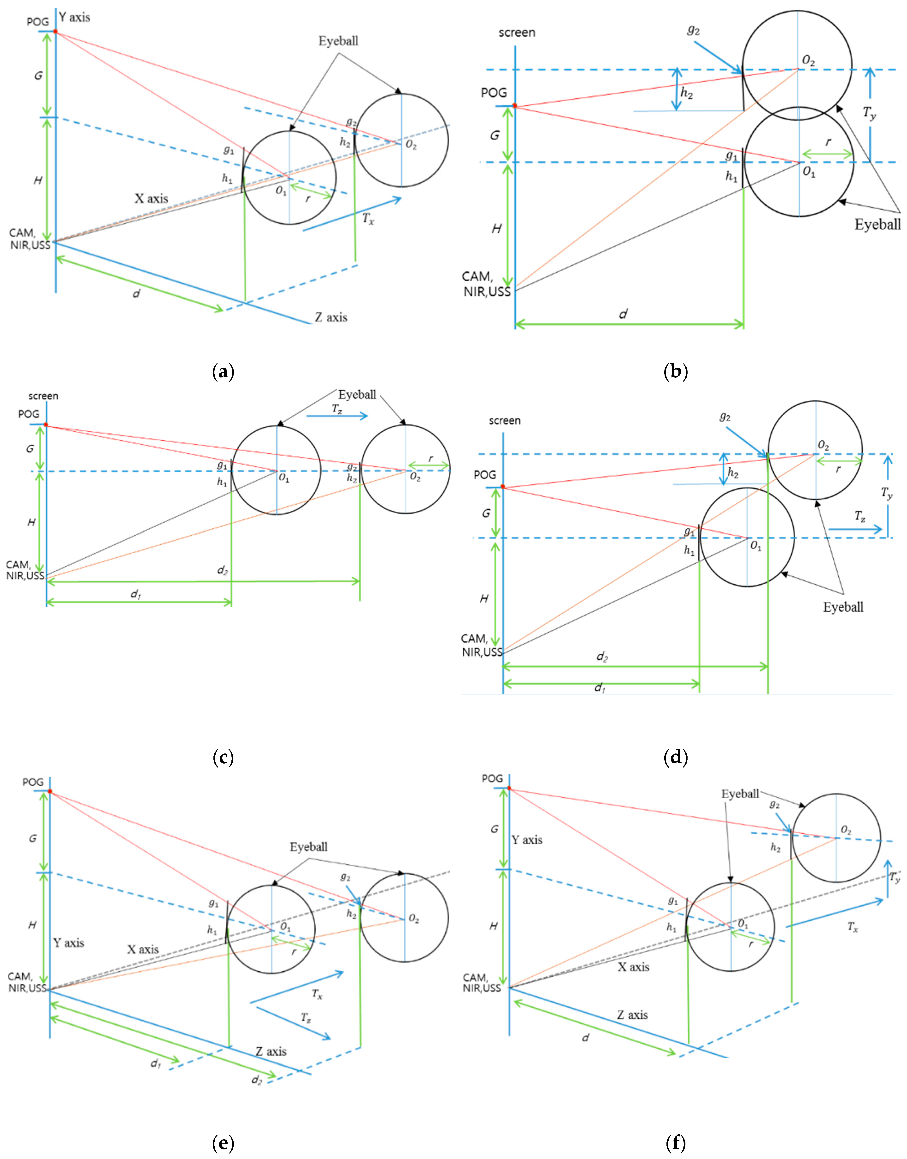
Figure 5, the circular shape represents a user’s eyeball, and
r is the radius of the eyeball based on Gullstrand’s eye model [
28]. POG means a point of gaze, and it is connected by user’s pupil center and eyeball’s center (
O1 or
O2).
G represents the distance from POG to the Y position of eyeball’s center
. H shows the distance from camera (CAM)/near infrared (NIR) illuminator/ultrasonic sensor (USS) to the Y position of eyeball’s center.
d represents the distance from X-Y plane to the nearest surface of eyeball.
g (
g1 or
g2) shows the distance from eyeball’s surface center to the line passing through POG and eyeball’s center.
h (
h1 or
h2) represents the distance from the eyeball’s surface center to the line passing through camera/NIR illuminator/ultrasonic sensor, and eyeball’s center. The line of camera/NIR illuminator/ultrasonic sensor, and eyeball’s center is passing though the point of corneal SR because NIR illuminator produces the corneal SR. Therefore, the pupil-corneal SR vector can be calculated from
g and
h. The eyeball of
h1,
g1,
O1, and
d1 of
Figure 5 represents the case before movement, and that of
h2,
g2,
O2, and
d2 of
Figure 5 shows the case after movement.
Figure 5.
Conceptual diagrams of the changes of pupil-corneal SR vector according to head movements: (a) T_X movement, (b) T_Y movement (side view), (c) T_Z movement (side view), (d) R_X movement (compound of T_Y and T_Z, side view), (e) R_Y movement (compound of T_X and T_Z), and (f) R_Z movement (compound of T_X and T_Y).
In case of T_X movement (
Figure 5a), we can obtain the Equations (3) and (4) based on the similarity property of triangle. From the Equations (3) and (4), we get the Equation (5). The approximate value of the pupil-corneal SR vector after T_X can be obtained as (
h2 + g2) as shown in Equation (6). This means that the pupil-corneal SR vector after T_X is same as that before T_X, and T_X does not change the original pupil-corneal SR vector:
In case of T_Y movement (
Figure 5b), we can obtain Equations (7) and (8) based on the similarity property of triangle. From Equations (7) and (8), we get Equation (9). The approximate value of the pupil-corneal SR vector after T_Y can be obtained as (
h2 – g2) as shown in Equation (10). This means that the pupil-corneal SR vector after T_Y is same as that before T_Y, and T_Y does not change the original pupil-corneal SR vector:
Using the same method, in
Figure 5c, we can obtain the pupil-corneal SR vector after T_Z as (
h2 + g2) as shown in Equation (14) using Equations (11)–(13). As shown in Equation (14), the pupil-corneal SR vector after T_Z is changed according to the Z-distance ratio, considering
r × ((
d1 +
r)/(
d2 +
r)) compared to the original pupil-corneal SR vector (
h1 + g1):
In case of R_X movement (
Figure 5d), we can decompose the R_X movement into T_Z and T_Y movements. As shown in
Figure 5b and Equation (10), T_Y does not change the original pupil-corneal SR vector. In addition, as shown in
Figure 5c and Equation (14), the pupil-corneal SR vector after T_Z is changed according to the Z-distance ratio considering
r × ((
d1 +
r)/(
d2 +
r)) compared to the original pupil-corneal SR vector (
h1 + g1). Therefore, we can obtain the pupil-corneal SR vector after R_X as shown in Equation (18), obtained using Equations (15)–(17):
In case of R_Y movement (
Figure 5e), we can decompose R_Y movement into T_Z and T_X movements. Using a similar method for the case of R_X movement, T_X does not change the original pupil-corneal SR vector as shown in
Figure 5a and Equation (6). In addition, the pupil-corneal SR vector after T_Z is changed according to the Z-distance ratio considering
r × ((
d1 +
r)/(
d2 +
r)) compared to the original pupil-corneal SR vector (
h1 + g1). Therefore, we can obtain the pupil-corneal SR vector after R_Y as shown in Equation (22), obtained using Equations (19)–(21):
Finally, for the last case of R_Z movement (
Figure 5f), we can decompose R_Z movement into T_X and T_Y movements. As explained before, T_X and T_Y do not change the original pupil-corneal SR vector. Therefore, the pupil-corneal SR vector after R_Z is same as that before R_Z, and R_Z does not change the original pupil-corneal SR vector as shown in Equation (26), obtained using Equations (23)–(25):
To summarize, we can estimate that the change of the pupil-corneal SR vector is only affected by the change of Z-distance (
Table 2).
Table 2.
Change of the pupil-corneal SR vector according to head movements.
Table 2.
Change of the pupil-corneal SR vector according to head movements.
| | X Axis | Y Axis | Z Axis |
|---|
| Translation | No change | No change | Change (Equation (14)) |
| Rotation | Change (Equation (18)) | Change (Equation (22)) | No change |
Although we assume that the Z-axis is orthogonal to the camera image plane as shown in
Figure 4, we do not use the assumption that the head movement of user in the direction of Z-axis is limited only to the parallel direction of Z-axis. That is, although the head movement of user is not parallel to the direction of Z-axis, this case can be handled in our research by considering the combination of
Tz and
Ty (or
Tz and
Tx) as shown in
Figure 5d,e.
2.3. Compensating the Head Movement
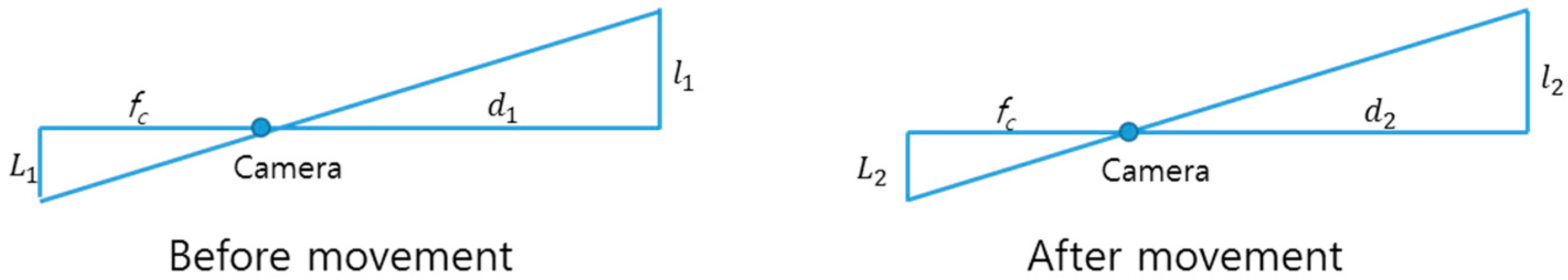
The Equations (14), (18) and (22) are obtained in 3D space. Therefore, we should obtain the corresponding Equations in 2D image plane in order to compensate the head movement because the pupil-corneal SR vector can be measured in 2D captured image. For that, we apply a camera perspective model [
24] as shown in
Figure 6.
fc is camera focal length,
d1 or
d2 is Z-distance, and
L1 or
L2 is the projection in image of
l1 or
l2 in 3D space. Then, we can get Equations (27) and (28). In Equations (14), (18) and (22),
or
is
l2, and
is
l1. Therefore, we can obtain the Equation (29) using the Equations (14), (18), (22) and (28). Finally, the Equation (30) can be obtained, where
L1 and
L2 are the pupil-corneal SR vectors in the image before and after head movement, respectively. We can compensate the head movement using the Equation (30).
Figure 6.
Camera perspective model.
Figure 6.
Camera perspective model.
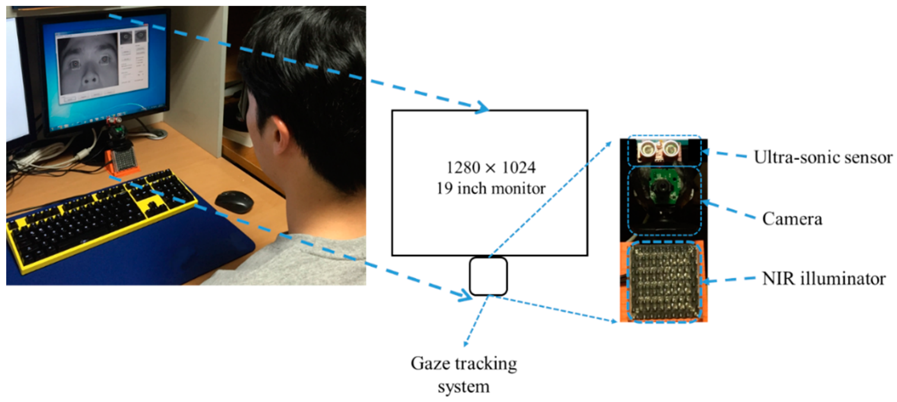
In order to compensate the head movement using Equation (30), we should know the Z-distances (
d1 and
d2) and the eyeball radius (
r). We refer to Gullstrand’s eye model [
28] for the eyeball radius. To get the Z-distance,
d1 and
d2, we use a commercial ultrasonic sensor (SRF08) [
29] set-up above the camera for gaze tracking. The sensor consists of two parts—transmitter & receiver— and a control board. The transmitter & receiver part is connected to the control board via an I2C interface. The control board is connected to a desktop computer via a universal serial bus (USB) 2.0 interface. Therefore, the Z-distance data measured by transmitter & receiver is continuously transmitted to the desktop computer via the control board at the frequency of 40 kHz. The maximum Z-distance which can be measured is limited to 6 m. The principle of the ultrasonic sensor is to measure the Z-distance between the transmitter & receiver and the object closest to the transmitter & receiver. Therefore, it is difficult to measure the accurate Z-distance between the ultrasonic sensor and the eye. Instead, it can measure the Z-distance between the ultrasonic sensor and another part of the face such as chin (or nose). In our research, the Z-distance between the chin (or nose) and eye is much smaller (2~3 cm) compared to the Z-distance (70~80 cm) between the chin (or nose) and ultrasonic sensor. Therefore, we can use the assumption that the Z-distances of the chin (or nose) and eye to the sensor are similar. In addition, the ultrasonic sensor can measure the Z-distance, even when a user wears glasses.
However, the stability for measuring an accurate Z-distance with the ultrasonic sensor is not high because the Z-distance can change even while the user’s head rotation is not changed in the Z-distance. To overcome this problem, we use the inter-distance between two eyes (pupil centers) (in the 3D space) which is measured during the initial stage of user calibration. The Z axis of the head in
Figure 4 is usually oriented towards the ultrasonic sensor when a user gazes at the center-lower position of the monitor (close to the position of the ultrasonic sensor) during the initial stage of user calibration. Then, we can obtain the Z-distance (
d) using the ultrasonic sensor and assume that
d is approximately the distance between the camera and user’s eye because the camera is close to the ultrasonic sensor. With the known camera focal length (
fc) (which is obtained by initial camera calibration), the measured Z-distance (
d), and the inter-distance between two pupil centers (in the image) (
L), we can obtain the actual inter-distance between two pupil centers (in the 3D space) (
l) using the equation (
l = (
d·
L)/
fc) based on camera perspective model of
Figure 6.
This actual inter-distance between two pupil centers (in the 3D space) (
l) is not changed even when head movement occurs. Therefore, since we know the inter-distance between two eyes (in the 3D space) (
l2 (=
l) of
Figure 6) and the changed inter-distance in the camera image after head movement (
L2 of
Figure 6) with the camera focal length (
fc), we can estimate the changed Z-distance after head movement (
d2 of
Figure 6) using the equation (
d2 = (
l2·
fc)/
L2).
In general, there are many individual variances of the inter-distance (
l) between two eyes (pupil centers) (in the 3D space). Therefore, if we use the average value (calculated from many people) of
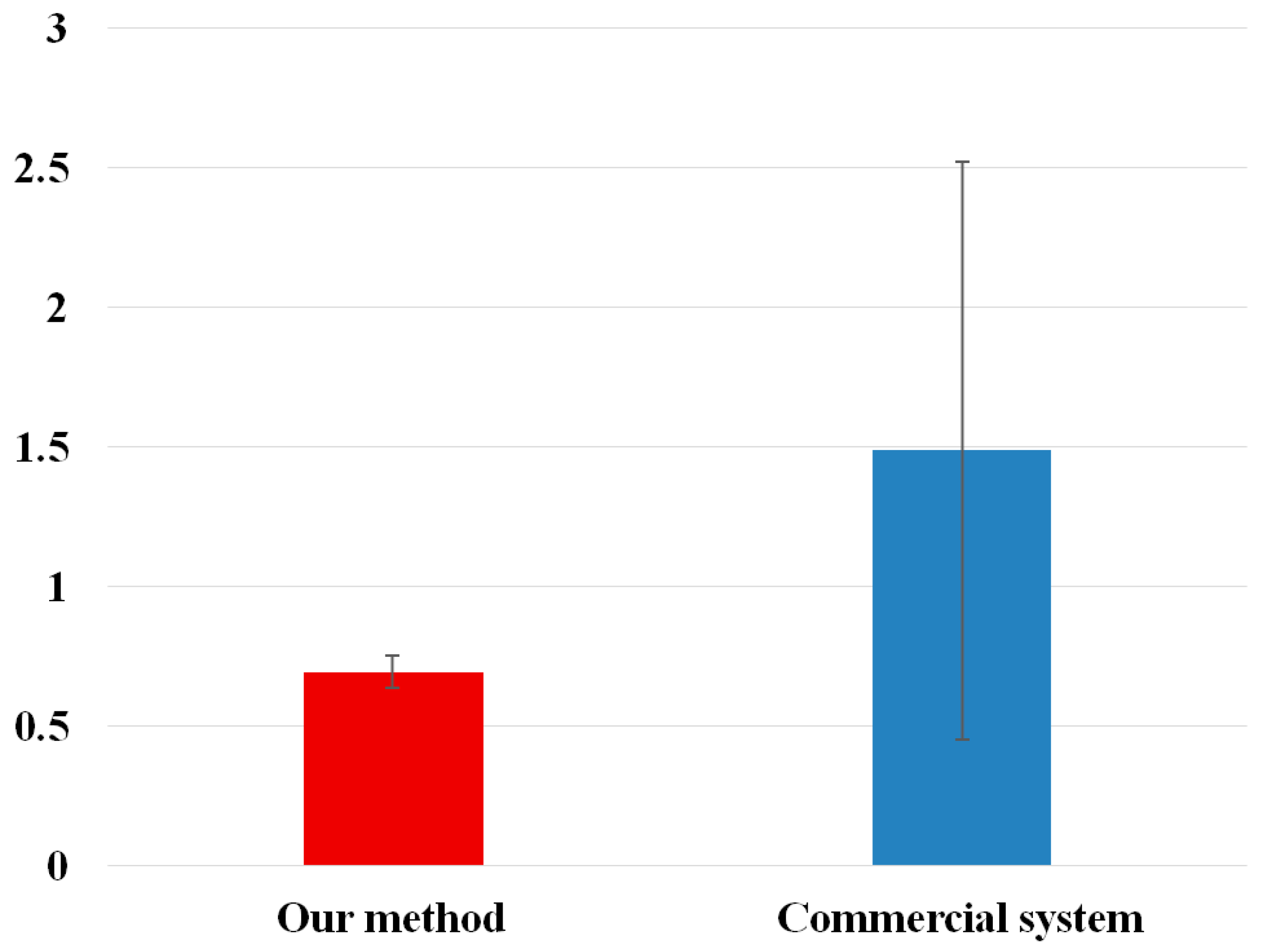
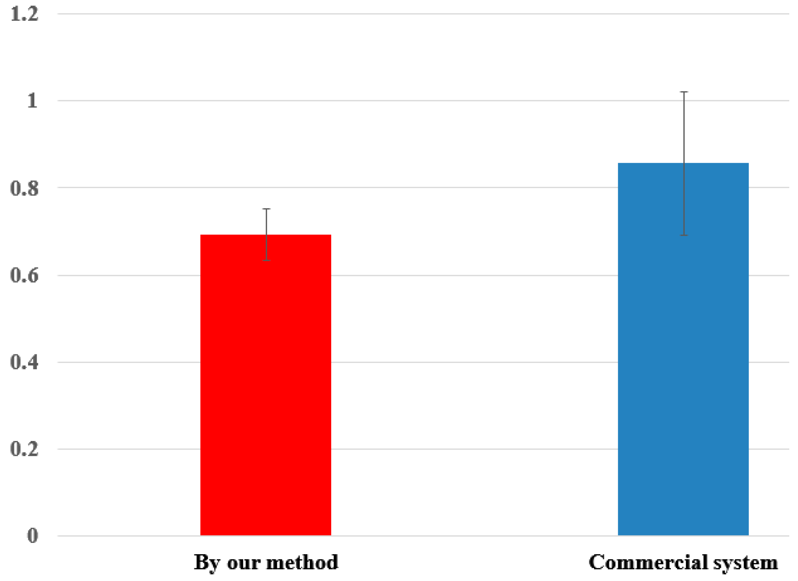
l for measuring the Z-distance, the measurement error of Z-distance is much higher than that by our method. Experimental results with 10 people showed that the measurement error of the Z-distance by using the average value of
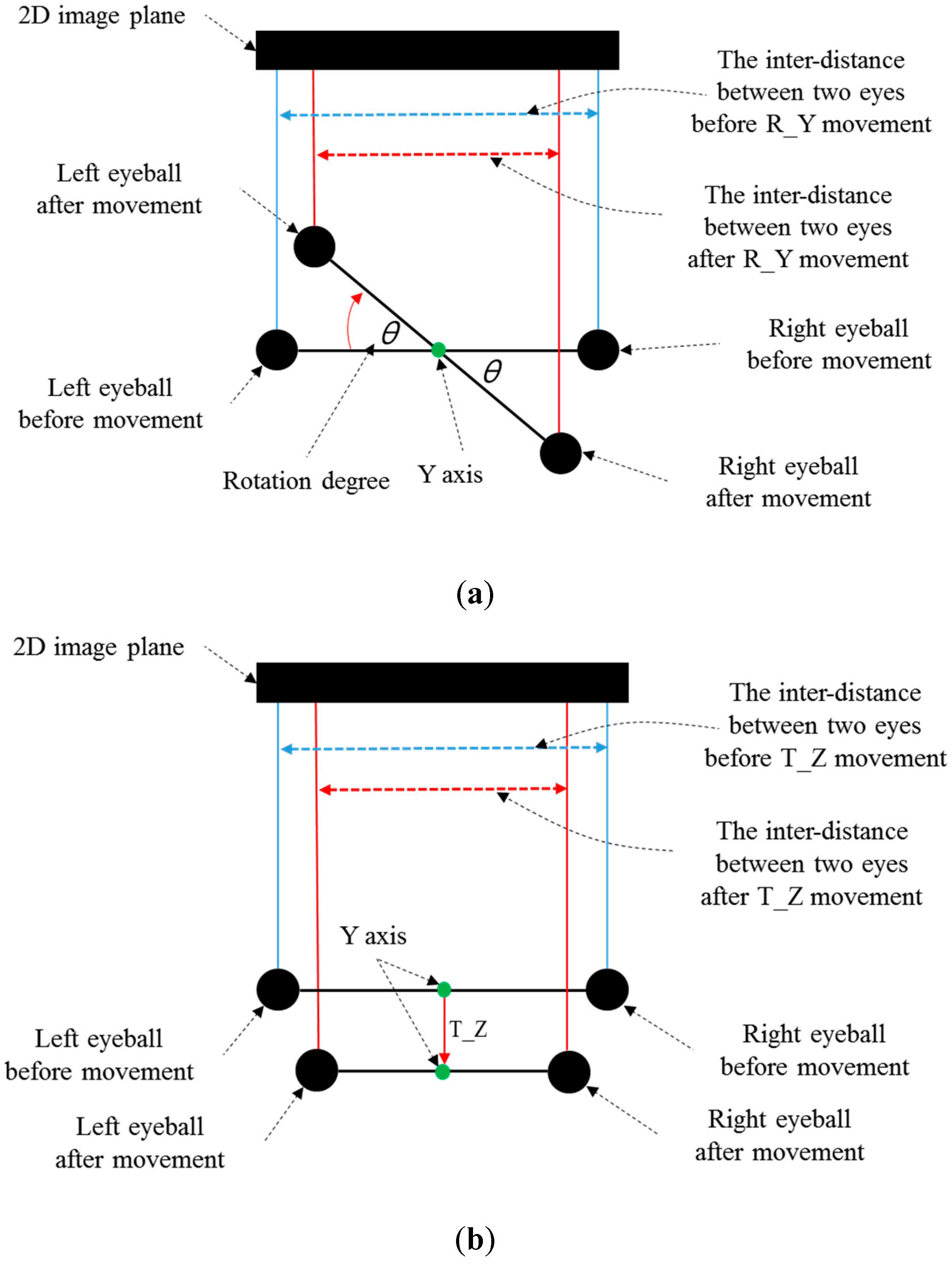
l (calculated from many people) was about 3.5 cm, while that measured by our method was less than 1 cm. However, in the case of R_Y movement, the inter-distance between two eyes and the corresponding Z-distance are measured incorrectly. This is caused by the mapping of the 3D space object into 2D. As shown in
Figure 7a,b, the inter-distance between two eyes in the 2D image plane becomes smaller in both cases of R_Y and T_Z. Although the pupil-corneal SR vector is changed, and it should be compensated in case of R_Y as shown in Equation (22), our system does not need to perform the compensation. The reason for this is our use of binocular gaze tracking. As shown in
Figure 7a, the left eye is closer to the monitor whereas the right one becomes farther away in the case of R_Y. Based on the Equations (22) and (30),
d2 is smaller in the case of the left eye whereas
d2 is larger in the case of the right one. Because our system uses binocular gaze tracking by obtaining the average gaze position of two eyes, the head movement by R_Y does not need to be compensated. However, in case of T_Z, the head movement must be compensated as shown in
Table 2. For that, our system should discriminate the R_Y and T_Z movement, which is achieved as explained below.
Figure 7.
Difference of the inter-distance between two eyes before and after (a) R_Y movement (b) T_Z movement (top view).
Figure 7.
Difference of the inter-distance between two eyes before and after (a) R_Y movement (b) T_Z movement (top view).
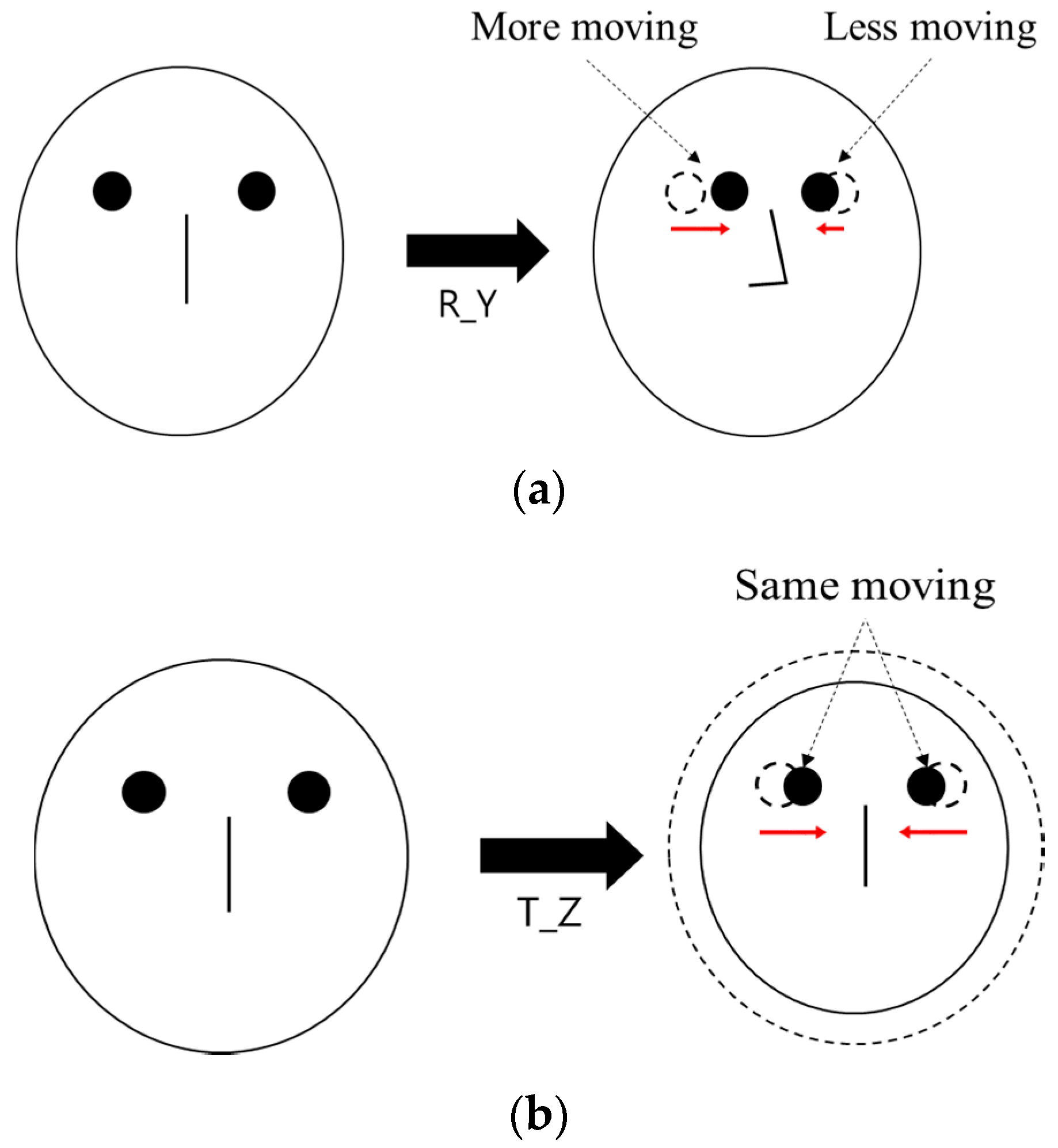
When R_Y movement occurs, the amount of movement of both eyes on the horizontal axis is different from each other as shown in
Figure 8a, whereas it is almost similar in case of T_Z movement as shown in
Figure 8b. Based on this, our system discriminates the case of R_Y movement from that of T_Z movement, and compensates the user’s head movement by compensating the pupil-corneal SR vector in the image based on Equation (30).
Figure 8.
Difference of the movement of both eyes on horizontal axis in case of (a) R_Y movement (b) T_Z movement.
Figure 8.
Difference of the movement of both eyes on horizontal axis in case of (a) R_Y movement (b) T_Z movement.


