
Energy Harvesting from Upper-Limb Pulling Motions for Miniaturized Human-Powered Generators


Abstract
:1. Introduction
2. Materials and Methods
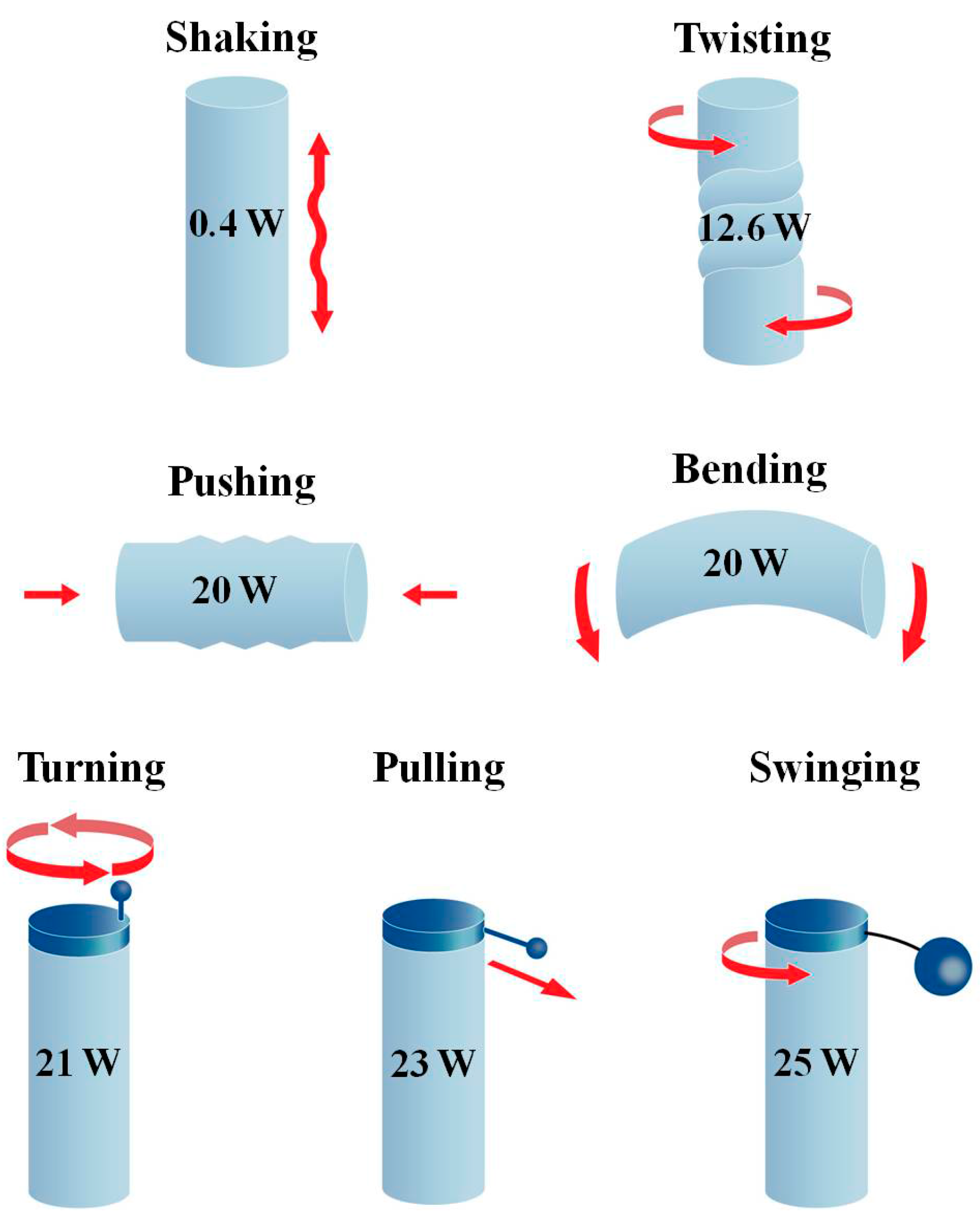
2.1. Human Motion for Power Production
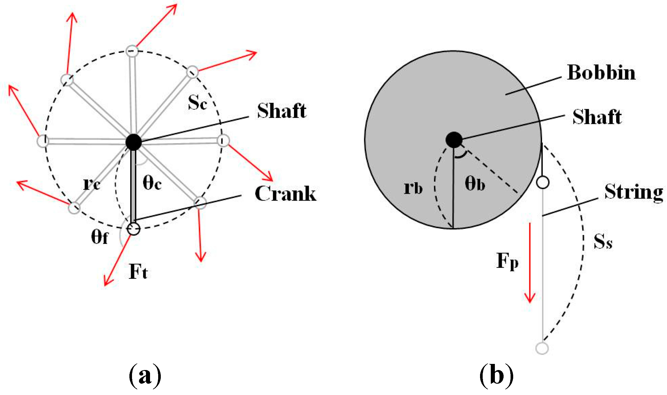
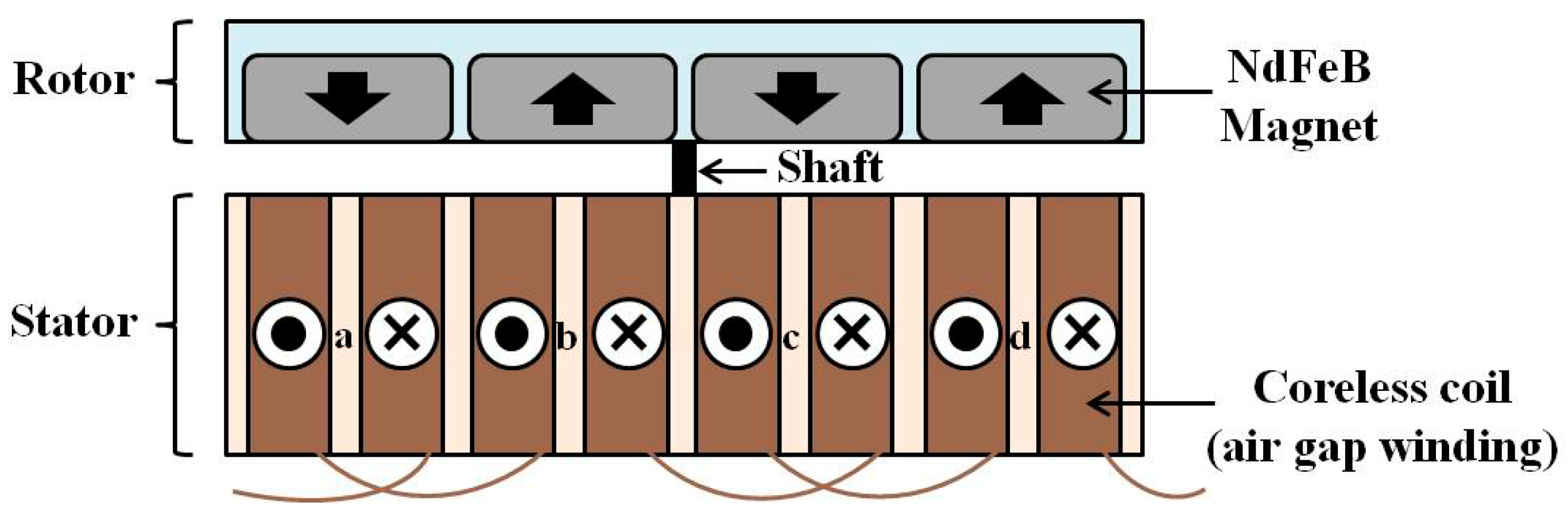
2.1.1. Mechanical Power Transfer into the Generator

| Symbols | Units | Variables | |
|---|---|---|---|
| Turning | rc | m | Length of crank handle |
| Sc | m | Displacement of crank-end | |
| θc | rad | Angular displacement of crank handle | |
| Ft | N | Force applied by upper limb | |
| θf | rad | Angle between the crank handle and the Ft | |
| Pulling | rb | m | Radius of bobbin |
| Ss | m | Displacement of string | |
| θb | rad | Angular displacement of bobbin | |
| Fp | N | Force applied by upper limb |
2.1.2. Economy of Human Limb Motion
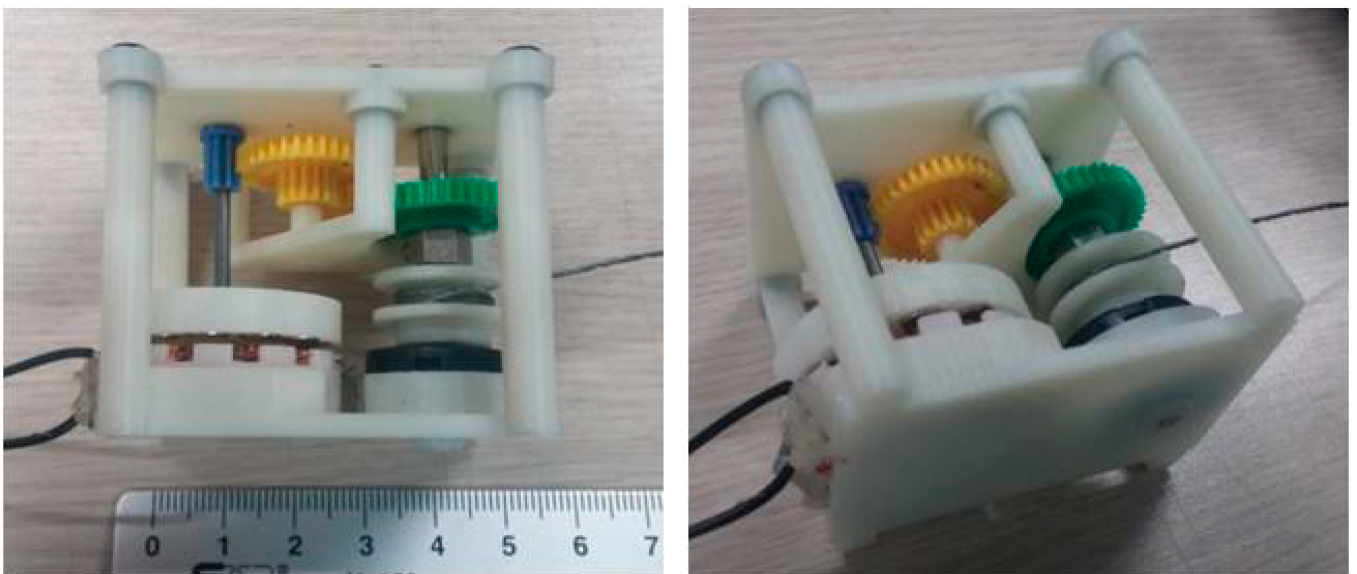
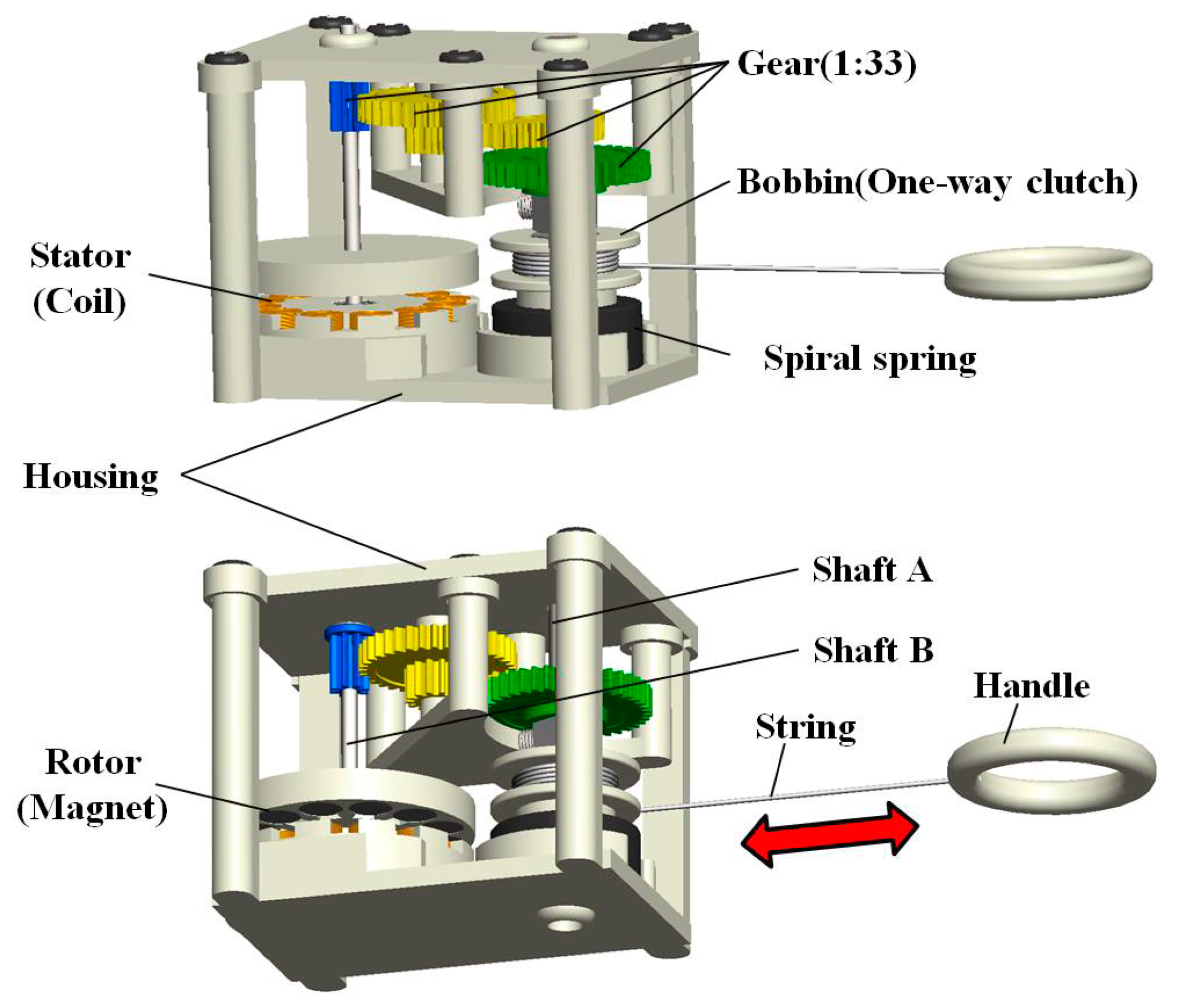
2.2. Design and Implementation of the Proposed Wearable Pulling Generator

| Variables (Units) | Value | |
|---|---|---|
| Mechanical parameters | Volume (mm3) | 50 × 32 × 43.5 |
| Weight (kg) | 0.05 | |
| Length of string (mm) | 180 | |
| Bobbin radius (mm) | 5.65 | |
| Gear ratio | 1:33 | |
| Electromagnetic parameters | Rotor diameter (mm) | 30 |
| Rotor thickness (mm) | 5 | |
| Magnet diameter (mm) | 5 | |
| Magnet thickness (mm) | 3 | |
| Magnet surface field (gauss) | 3850 | |
| Number of rotor magnets | 12 | |
| Stator diameter (mm) | 30 | |
| Stator thickness (mm) | 8 | |
| Outer diameter of solenoid coil in stator (mm) | 1 | |
| Inner diameter of solenoid coil in stator (mm) | 8 | |
| Wire diameter of solenoid coil in stator (mm) | 0.15 | |
| Number of turns in solenoid coil | 380 (each coils) | |
| Number of solenoid coils in stator | 12 | |
| Total resistance of the solenoid coils (Ω) | 36 |
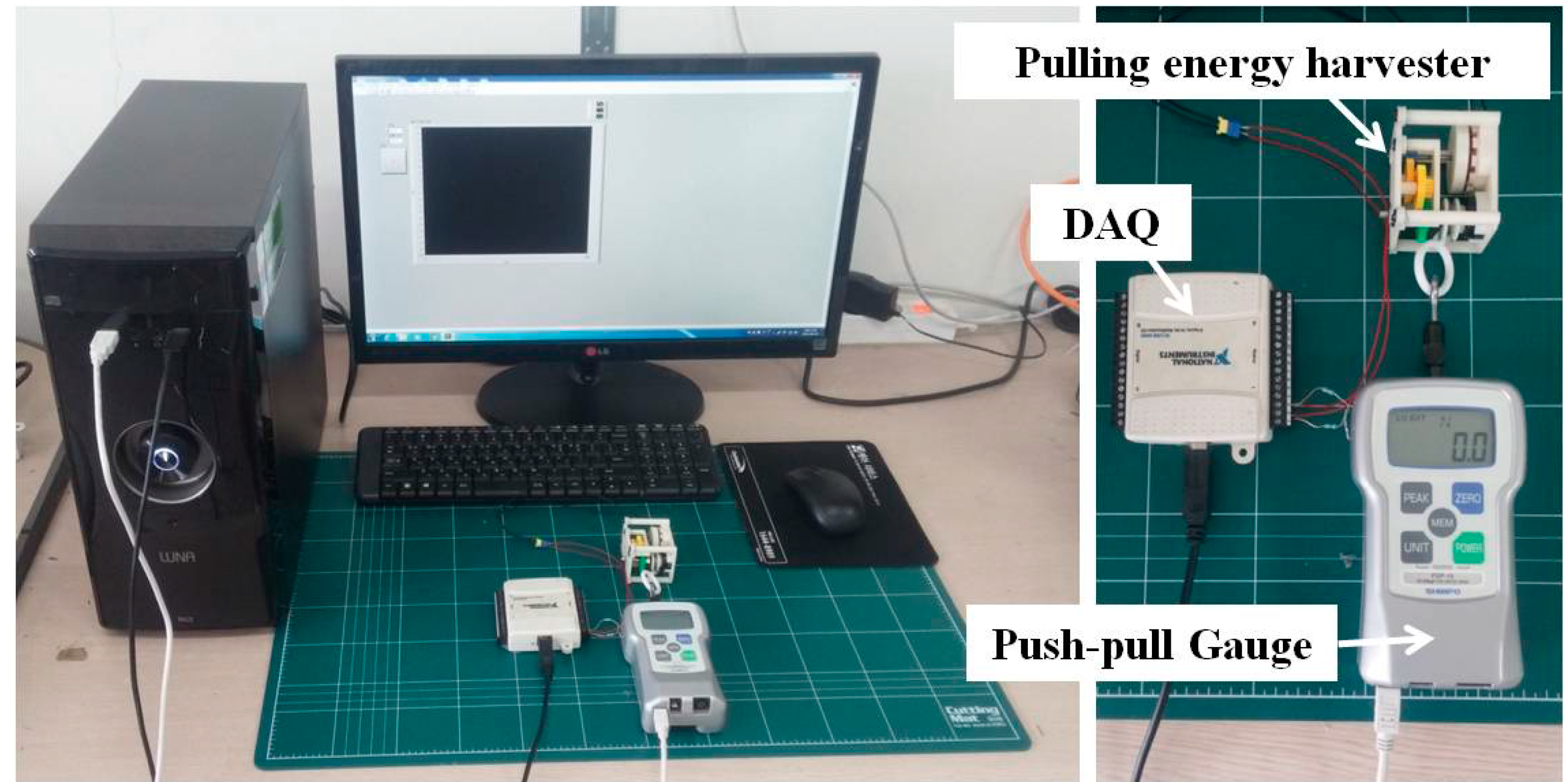
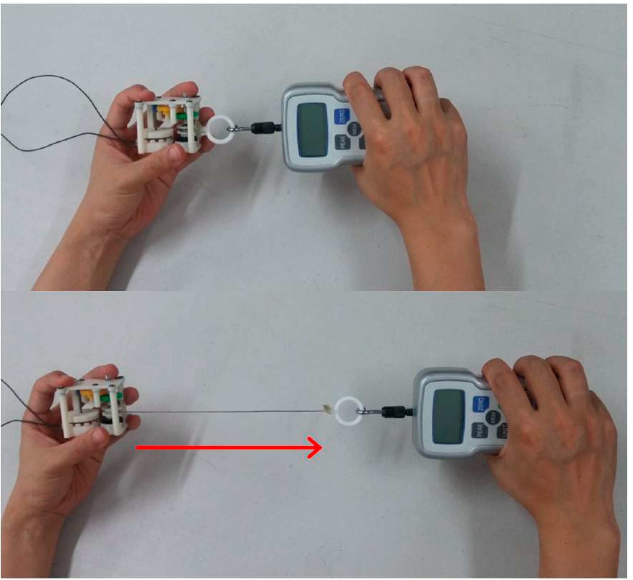
2.3. Experiments

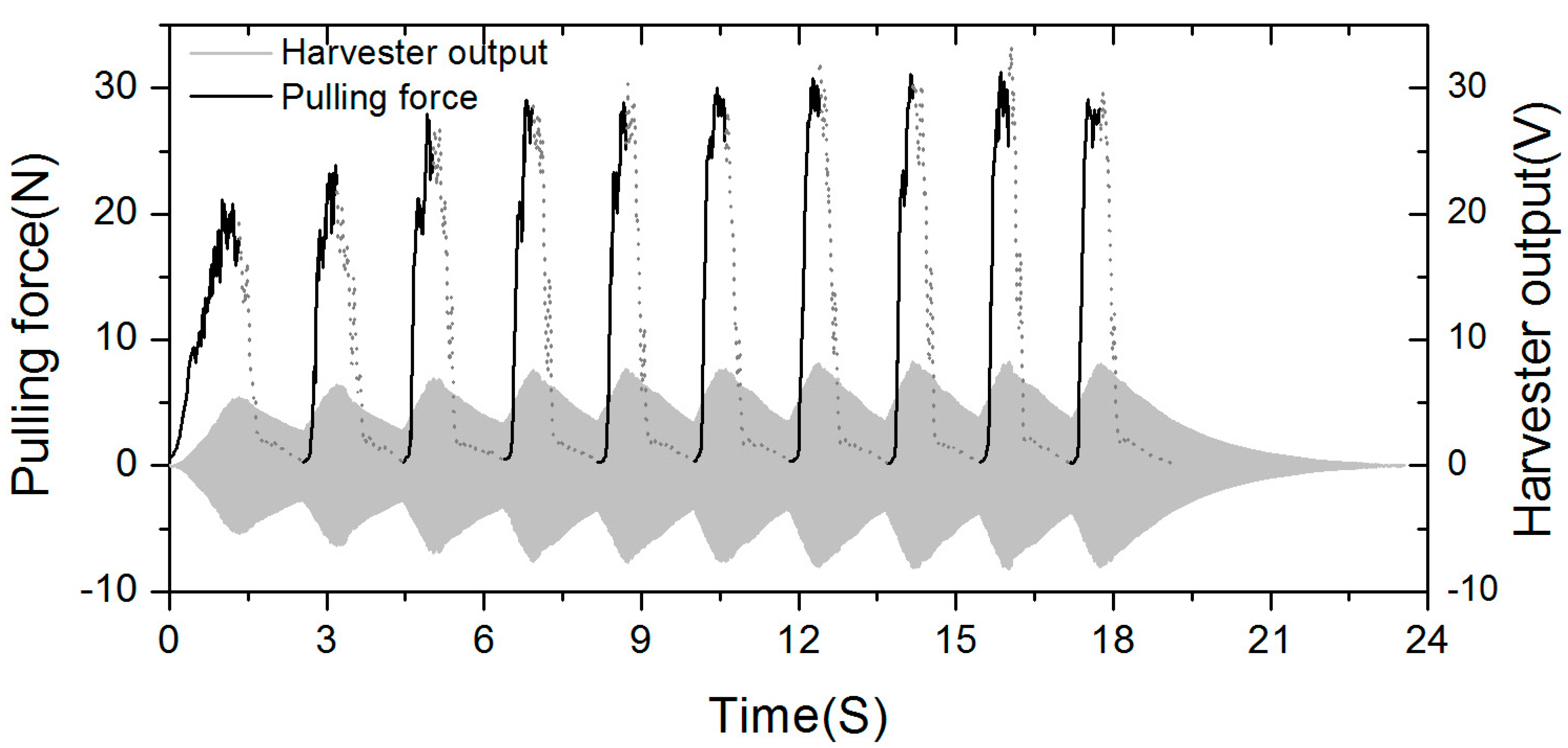
3. Results and Discussions
| Pulling Section | Length of Pulled String (mm) | Avg. Pulling Force (N) | Avg. RPM of Magnet Rotor | Period of Time of Pulling (s) | Period of Time of Flywheel (s) |
|---|---|---|---|---|---|
| 1 | 129 | 11.3474 | 2843 | 1.3215 | 1.2201 |
| 2 | 124 | 12.7651 | 3650 | 0.6480 | 1.2606 |
| 3 | 117 | 14.9333 | 3399 | 0.5789 | 1.3472 |
| 4 | 128 | 15.0706 | 4037 | 0.5553 | 1.225 |
| 5 | 127 | 13.8417 | 3884 | 0.5525 | 1.2822 |
| 6 | 153 | 18.1973 | 4640 | 0.6127 | 1.2270 |
| 7 | 144 | 15.6972 | 4352 | 0.5660 | 1.2830 |
| 8 | 124 | 14.4063 | 3950 | 0.5000 | 1.2610 |
| 9 | 151 | 17.0400 | 4879 | 0.5750 | 1.1580 |
| 10 | 144 | 17.1082 | 1263 | 0.5880 | 5.7880 |
| Pulling Cycle | Input Energy (J) | Output Energy (J) | Avg. Input Power (W) | Avg. Output Power (W) | Max. Input Power (W) | Max. Output Power (W) |
|---|---|---|---|---|---|---|
| 1 | 2.0782 | 0.4224 | 1.5735 | 0.1662 | 5.0785 | 0.8100 |
| 2 | 1.8568 | 0.5301 | 2.8681 | 0.2777 | 7.7463 | 1.1374 |
| 3 | 2.0360 | 0.6536 | 3.5200 | 0.3393 | 8.3403 | 1.3352 |
| 4 | 2.2768 | 0.7367 | 4.1039 | 0.4138 | 11.6580 | 1.6248 |
| 5 | 2.1013 | 0.7766 | 3.8067 | 0.4233 | 10.4961 | 1.6337 |
| 6 | 3.2099 | 0.7999 | 5.2390 | 0.4348 | 10.8481 | 1.6397 |
| 7 | 2.6957 | 0.8658 | 4.7635 | 0.4682 | 11.8695 | 1.8293 |
| 8 | 2.1400 | 0.8698 | 4.2800 | 0.4939 | 11.9620 | 1.8420 |
| 9 | 3.0142 | 0.8438 | 5.2430 | 0.4869 | 12.4095 | 1.8879 |
| 10 | 2.8904 | 1.0364 | 4.9174 | 0.1625 | 11.1328 | 1.8333 |

| Mechanical Input | Electrical Output | Conversion Efficiency | ||
|---|---|---|---|---|
| Energy (J) | Power (W) | Energy (J) | Power (W) | Ratio (%) |
| 24.30 | 3.74 | 7.53 | 0.32 | 30.98 |
4. Conclusions/Outlook
Acknowledgments
Author Contributions
Conflicts of Interest
References
- Robion, A.; Sadarnac, D.; Lanzetta, F.; Marquet, D.; Rivera, T. Breakthrough in Energy Generation for Mobile or Portable Devices. In Proceedings of the IEEE Telecommunications Energy Conference 29th International, Rome, Italy, 30 September–4 October 2007; pp. 460–466.
- Starner, T. Human-powered Wearable Computing. IBM Syst. J. 1996, 35, 618–629. [Google Scholar] [CrossRef]
- Kymissis, J.; Kendall, C.; Paradiso, J.; Gershenfeld, N. Parasitic Power Harvesting in Shoes. In Proceedings of IEEE Second International Symposium on Wearable Computers, Pittsburgh, PA, USA, 19–20 October 1998; pp. 132–139.
- Rocha, J.G.; Goncalves, L.M.; Rocha, P.F.; Silva, M.P.; Lanceros-Mendez, S. Energy Harvesting from Piezoelectric Materials Fully Integrated in Footwear. IEEE Trans. Ind. Electron. 2010, 57, 813–819. [Google Scholar] [CrossRef]
- Carroll, D.; Duffy, M. Modelling, Design, and Testing of an Electromagnetic Power Generator Optimized for Integration into Shoes. J. Syst. Control Eng. 2012, 226, 256–270. [Google Scholar] [CrossRef]
- Donelan, J.M.; Li, Q.; Naing, V.; Hoffer, J.A.; Weber, D.J.; Kuo, A.D. Biomechanical Energy Harvesting: Generating Electricity During Walking with Minimal User Effort. Science 2008, 319, 807–810. [Google Scholar] [CrossRef] [PubMed]
- Kuo, A.D. Harvesting Energy by Improving the Economy of Human Walking. Science 2005, 309, 1686–1687. [Google Scholar] [CrossRef] [PubMed]
- Feenstra, J.; Granstrom, J.; Sodano, H. Energy Harvesting Through a Backpack Employing a Mechanically Amplified Piezoelectric Stack. Mech. Syst. Signal Process. 2008, 22, 721–734. [Google Scholar] [CrossRef]
- Delnavaz, A.; Voix, J. Electromagnetic Micro-power Generator for Energy Harvesting from Breathing. In Proceedings of In IECON 2012-38th Annual Conference on IEEE Industrial Electronics Society, Montreal, Canada, 25–28 October 2012; pp. 984–988.
- Shahhaidar, E.; Padasdao, B.; Romine, R.; Stickley, C.; Boric Lubecke, O. Electromagnetic Respiratory Effort Harvester: Human Testing and Metabolic Cost Analysis. IEEE J. Biomedi. Health Inform. 2015, 19, 399–405. [Google Scholar] [CrossRef] [PubMed]
- Eton Corporation. Available online: http://www.etoncorp.com/ (accessed on 26 June 2015).
- K-TOR®. Available online: http://www.k-tor.com/ (accessed on 26 June 2015).
- Kuipers, R.J. Engineering a Human Powered MP3 Player; Graduation Report; Delft University of Technology: Delft, Netherlands, May 2003. [Google Scholar]
- Gribble, P.L.; Mullin, L.I.; Cothros, N.; Mattar, A. Role of Cocontraction in Arm Movement Accuracy. J. Neurophysiol. 2003, 89, 2396–2405. [Google Scholar] [CrossRef] [PubMed]
- Uno, Y.; Kawato, M.; Suzuki, R. Formation and Control of Optimal Trajectory in Human Multijoint Arm Movement. Biol. Cybern. 1989, 61, 89–101. [Google Scholar] [CrossRef] [PubMed]
- Ani, S.O.; Bang, D.; Polinder, H.; Lee, J.Y.; Moon, S.R.; Koo, D.H. Human Powered Axial Flux Permanent Magnet Machines: Review and Comparison. In Proceedings of the IEEE Energy Conversion Congress and Exposition (ECCE), Atlanta, GA, USA, 12–16 September 2010; pp. 4165–4170.
- Mahmoudi, A.; Ping, H.W.; Rahim, N.A. A Comparison between the TORUS and AFIR Axial-Flux Permanent-magnet Machine Using Finite Element Analysis. In Proceedings of the 2011 IEEE International Electric Machines & Drives Conference (IEMDC), Niagara Falls, Canada, 15–18 May 2011; pp. 242–247.
- Louie, H.; Peng, K.; Hoffstetter, E.; Szablya, S.J. Design and Testing of a Small Human-powered Generator for Developing Rural Communities. In Proceedings of the 2010 IEEE North American Power Symposium (NAPS), Arlington, MA, USA, 26–28 September 2010; pp. 1–8.
- Badshah, A.; Gupta, S.; Cohn, G.; Villar, N.; Hodges, S.; Patel, S.N. Interactive Generator: A Self-Powered Haptic Feedback Device. In Proceedings of the SIGCHI Conference on Human Factors in Computing Systems, Vancouver, Canada, 7–12 May 2011; pp. 2051–2054.
- Dauner, J.M.; Karagozler, M.E.; Poupyrev, I. Paper Generators: Harvesting Energy from Touching, Rubbing and Sliding. In Proceedings of the CHI 14 Extended Abstracts on Human Factors in Computing Systems, Toronto, Canada, 26 April–1 May 2014; pp. 161–162.
- Ryokai, K.; Su, P.; Kim, E.; Rollins, B. Energy Bugs: Energy Harvesting Wearables for Children. In Proceedings of the 32nd annual ACM conference on Human factors in computing systems, Toronto, Canada, 26 April–1 May 2014; pp. 1039–1048.
© 2015 by the authors; licensee MDPI, Basel, Switzerland. This article is an open access article distributed under the terms and conditions of the Creative Commons Attribution license (http://creativecommons.org/licenses/by/4.0/).
Share and Cite
Yeo, J.; Ryu, M.-h.; Yang, Y. Energy Harvesting from Upper-Limb Pulling Motions for Miniaturized Human-Powered Generators. Sensors 2015, 15, 15853-15867. https://doi.org/10.3390/s150715853
Yeo J, Ryu M-h, Yang Y. Energy Harvesting from Upper-Limb Pulling Motions for Miniaturized Human-Powered Generators. Sensors. 2015; 15(7):15853-15867. https://doi.org/10.3390/s150715853
Chicago/Turabian StyleYeo, Jeongjin, Mun-ho Ryu, and Yoonseok Yang. 2015. "Energy Harvesting from Upper-Limb Pulling Motions for Miniaturized Human-Powered Generators" Sensors 15, no. 7: 15853-15867. https://doi.org/10.3390/s150715853