Characterization of Piezoresistive PEDOT:PSS Pressure Sensors with Inter-Digitated and Cross-Point Electrode Structures


Abstract
: The piezoresistive characteristics of poly(3,4-ethylenedioxythiophene):polystyrene sulfonate (PEDOT:PSS) pressure sensors with inter-digitated (IDE) and cross-point electrode (CPE) structures have been investigated. A small variation of the resistance of the pressure sensors with IDE without bottom indium-tin-oxide (b-ITO) film and with CPE structures was observed owing to the single carrier-conducting pathway. For the IDE pressure sensors with b-ITO, the piezoresistive characteristics at low and high pressure were similar to those of the pressure sensors with IDE without b-ITO and with CPE structures, respectively, leading to increased piezoresistive pressure sensitivity as the PEDOT:PSS film thickness decreased. A maximum sensitivity of more than 42 kΩ/Pa was achieved. When the normal pressure was applied, the increased number of conducting points or the reduced distance between the PEDOT oligomers within the PEDOT:PSS film resulted in a decrease of the resistance. The piezoresistive pressure sensors with a single carrier-conducting pathway, i.e., IDE without b-ITO and CPE structures, exhibited a small relaxation time and a superior reversible operation, which can be advantageous for fast piezoresistive response applications.1. Introduction
Pressure sensors have a great significance for industrial equipment and they are widely used for the control and monitoring of thousands of applications, such as biomedical, environment, space, and automobiles [1–4]. Many works have been conducted on pressure measurement using various techniques and three major types of pressure sensors have been investigated using capacitive, piezoelectric, and piezoresistive measurements [5–8]. For example, capacitive pressure sensors use a diaphragm and a pressure cavity to create a variable capacitance for detecting strain by applying pressure. Common diaphragm materials are metal, ceramic, and silicon [5,6]. Capacitive pressure sensors have been reported to be suitable for low-pressure measurements because of their sensitive diaphragms, but the linearity of their capacitance is poor due to the parasitic issue during the measurement. For piezoelectric pressure sensors, the piezoelectric effect in certain materials, such as quartz, has been used to measure the strain [5,7]. This technology is commonly employed to measure highly dynamic pressure phenomena but it is insensitive to static responses. Furthermore, piezoresistive pressure sensors have been proposed to detect the strain by applying pressure to change the resistance of test patterns. Materials typically used for piezoresistive pressure sensors are silicon, polysilicon thin films, bonded metal foils, sputtered thin films, and inkjet printing films [5,8–10]. Generally, piezoresistive pressure sensors are the most commonly employed technology in the pressure sensor market owing to their advantages of high sensitivity and low cost.
Conducting polymers have been widely used in organic electronics after their discovery by Shirakawa et al. [11,12] because they exhibit promising properties, such as high flexibility, low-cost fabrication process, light weight, and easy tailoring, to obtain the required performance [13,14]. Aside from the above characteristics, some conducting polymers also possess the unique piezoresistive property, which can be used for strain sensor applications [15]. Among conductive materials, poly(3,4-ethylenedioxythiophene) (PEDOT) has gained an outstanding position for pressure sensor applications owing to its high electrochemical and thermal stability, high conductivity, good optical properties, and high transparency [16,17]. To balance the cationic charge of PEDOT and allow the dispersion of PEDOT in water, polystyrene sulfonate (PSS) is introduced to form the water-soluble polymer PEDOT:PSS [17]. PEDOT:PSS can be applied in solid electrolyte capacitors [18], antistatic coatings [19], and anode electrodes in organic electronic devices, such as light-emitting diodes [20], field effect transistors [21], photovoltaic cells [22], and flexible sensors on sensing skin [23]. Moreover, strain sensors with PEDOT:PSS on polyimide and polyethylene terephthalate (PET) flexible substrates have been demonstrated to present sufficient piezoresistive properties for biosensor applications [24–26].
There are two types of electrode patterns being considered for piezoresistive pressure sensors. Inter-digitated electrode (IDE) structures, with feature size in the nanometer scale, are popular in the solid-state physics community and they have been implemented in various devices, including surface acoustic wave (SAW) sensors [27], chemical sensors [28], micro-electro-mechanical systems (MEMS) biosensors [29], and semi-conducting nanowires [30]. The output signal strength of IDEs is controlled through a careful design of the active area, width, and spacing of the electrode fingers. On the other hand, for the cross-point electrode (CPE) structure, the active sensing material is sandwiched between two patterned electrodes. The CPE structure is widely used for emerging memory applications, especially for resistive random access memory (RRAM) devices [31,32]. It has also been used for the high-density strain sensor arrays, where the number of active cells can be increased by increasing the number of top and bottom electrodes [33,34]. However, the effects of IDE and CPE structures on piezoresistive pressure sensors have not yet been understood. In this work, PEDOT:PSS piezoresistive pressure sensors fabricated on a flexible PET substrate with IDE and CPE structures were investigated. The piezoresistive characteristics of these three structures, IDEs with and without b-ITO and a CPE, are strongly dependent on the PEDOT:PSS thickness, which have been examined to be due to the different carrier conducting pathways. Consequently, a specific piezoresistive structure is suggested to achieve a high piezoresistive sensitivity and a small relaxation time with less variation of the resistance, which can be used for future piezoresistive applications.
2. Experimental Procedures
2.1. Fabrication of the PEDOT:PSS Pressure Sensors
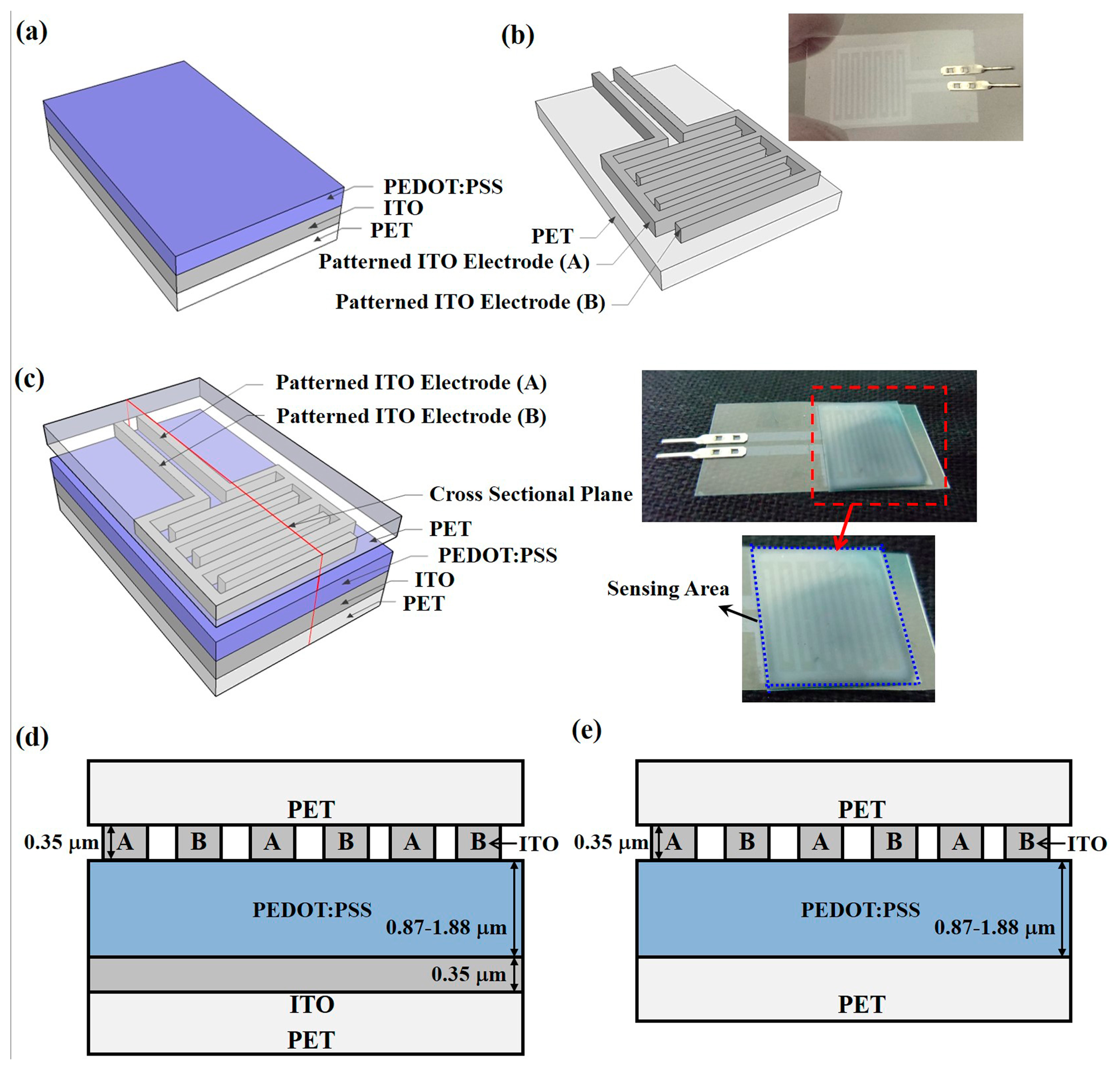
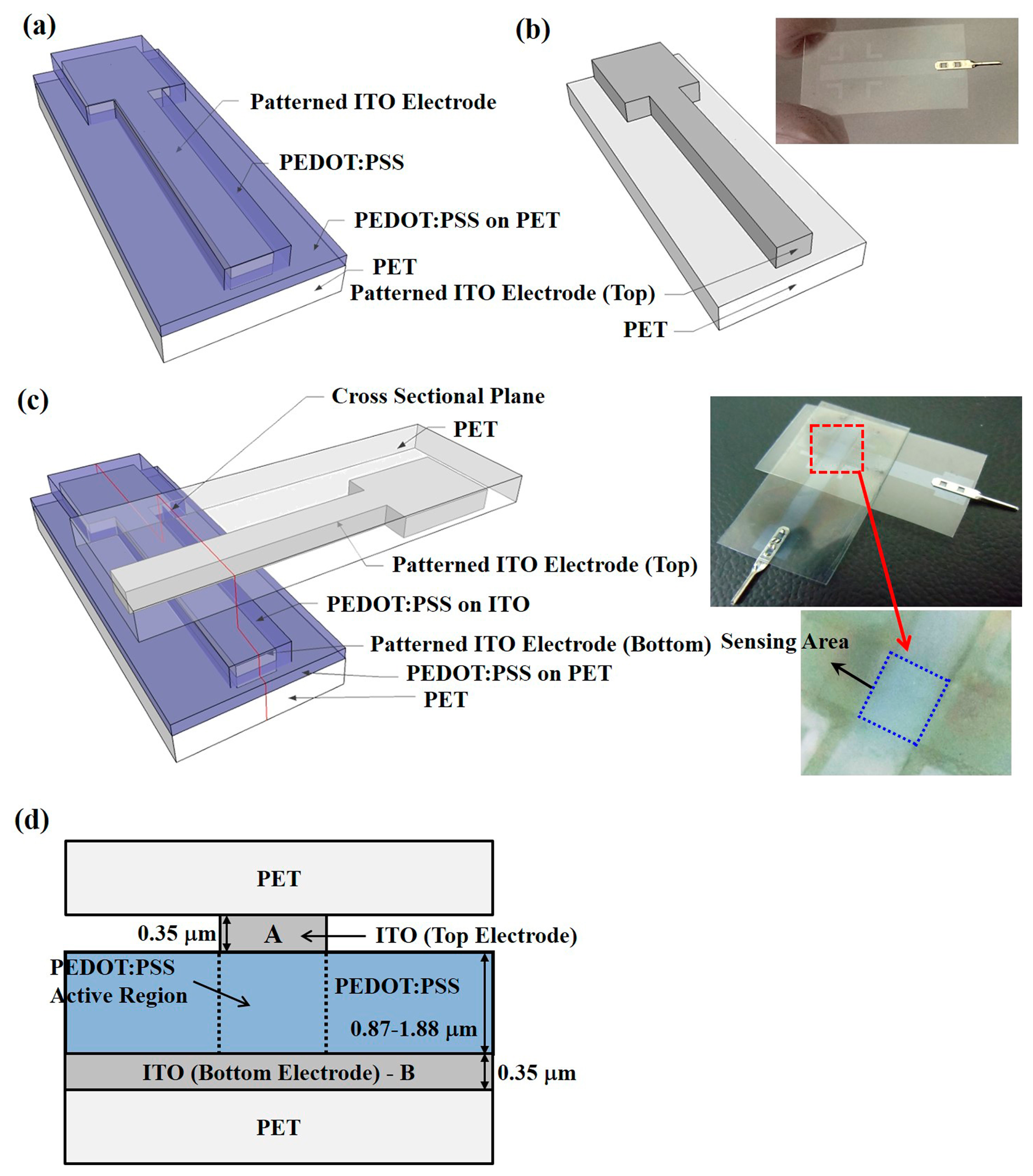
The piezoresistive pressure sensors with the PEDOT:PSS conductive material were fabricated on ITO-coated PET substrates. The ITO-coated PET substrates were provided by Win Optical Technology (Taoyuan, Taiwan) and the ITO film was deposited by radio-frequency (RF) sputtering using a roll-to-roll process. ITO with a thickness of 0.35 μm was used as the electrode material, providing the advantages of a high electron density of 1021 cm−3 in the conduction band and sufficient stability in aqueous solutions for electrochemical applications [35]. Furthermore, ITO also shows transparency to visible light, which enables multiple parameter measurements by using optical and electrical techniques [36]. Two structures, an IDE and a CPE, were prepared, as illustrated in Figures 1 and 2, which show their schematic diagrams, sensor device images, and cross-sectional structures. For part I of the pressure sensors with IDE structures, shown in Figure 1a, the ITO-coated PET substrate was first treated by O2 plasma to make the ITO film hydrophilic for the successful coating of PEDOT:PSS films [37]. PEDOT:PSS was spin-coated on the b-ITO films with speeds of 500, 750, and 1000 rpm to obtain an average film thickness of 1.88, 1.32, and 0.87 μm, respectively, measured by an ellipsometer. A PEDOT:PSS solution with a concentration of 1.56 wt. % was synthesized to obtain a PEDOT:PSS film resistivity of 4.85 × 10⁷ Ω-cm by a Hall measurement [38,39]. The use of PEDOT:PSS films with such a high resistivity is due to the need to achieve a suitable piezoresistive response. Subsequently, to make the film dry, all samples were baked at 90 °C for 10 min using a hot plate. For comparison, the PET substrate without b-ITO was also spin-coated with PEDOT:PSS film. On the other hand, for part I of the pressure sensors with CPE structures shown in Figure 2a, the ITO bottom electrode was first patterned using an aqua regia solution to obtain the desired patterns. The samples were then treated by O2 plasma, spin-coated using the PEDOT:PSS solution, and finally baked. For part II, the ITO electrodes were patterned to form the fingers and top electrodes of the pressure sensors with IDE (Figure 1b) and CPE structures (Figure 2b), respectively. For the sensors with IDE structures, the width and spacing of each finger was 500 μm. Because the width of the top and bottom electrodes was 3000 μm, the active cell area of the sensors with CPE structures was 9 × 106 μm2. Figure 1c shows the schematic diagram and image of the final sensor devices with IDE structures, and those of the devices with CPE structures are presented in Figure 2c. From the red cut-line shown in Figures 1c and 2c, the cross-sectional structures of the pressure sensors with IDE with b-ITO and CPE structures were obtained and they are illustrated in Figures 1d and 2d, respectively. In addition, the cross-sectional structure of IDE pressure sensors without b-ITO is also displayed in Figure 1e. All parameters of the piezoresistive pressure sensors with IDE and CPE structures are summarized in Table 1.
2.2. Characterization Methodology
After the piezoresistive pressure sensors had been fabricated, their electrical properties were characterized using a Keithley 2450 interactive digital source meter (Keithley Instruments Inc., Cleveland, OH, USA). The samples were placed on a homemade sample holder fabricated by rigid steel and the pressure in vertical direction, also called the normal pressure, was applied using a JSV H1000 vertical stand (ALGOL Instrument Co., Ltd., Taoyuan, Taiwan) equipped with an ALGOL force gauge. A quartz buffer layer of 108 μm2, larger than the active area, was used to provide an equal pressure distribution throughout the sensor area. A normal pressure of 0.1 to 20 kPa with a speed of 2 mm/min was applied on the samples to obtain the piezoresistive characteristics at low pressure and identify the carrier conducting pathways of each structure to avoid breaking of quartz plate. Additionally, the reversible testing of the response properties of the pressure sensors was performed with a holding time (th) of 10 s.
3. Results and Discussion
3.1. Piezoresistive Characteristics
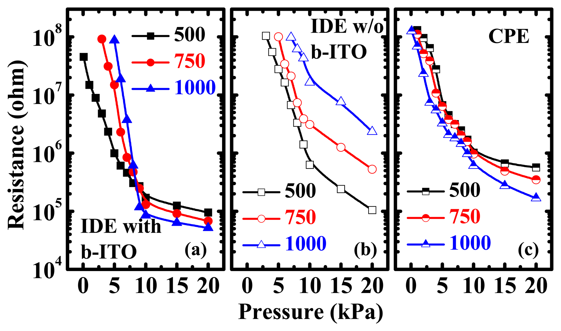
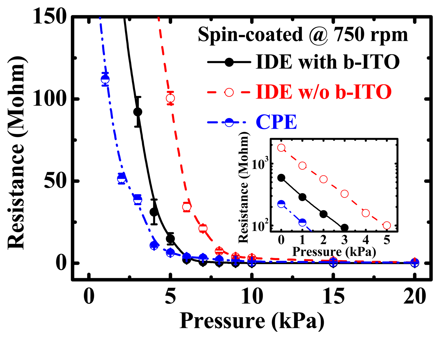
Figure 3 shows the resistance versus pressure (R-P) characteristics of the PEDOT:PSS pressure sensors with IDE and CPE structures. The low-pressure properties of these sensors are also depicted in the inset figure. A spin speed of 750 rpm was used to coat PEDOT:PSS film on the flexible PET substrates. To obtain the statistical distribution, at least 20 samples were measured for each pressure sensor. As the applied normal pressure increases, the measured resistance decreases, demonstrating the well-known piezoresistive property. It was obtained that the piezoresistive pressure sensitivity of these three samples was approximately 33.73 to 35.66 kΩ/Pa. Compared with IDEs with b-ITO, the pressure sensors with IDEs without b-ITO and with CPE structures presented a smaller variation in the measured resistance. The initial resistance, i.e., the resistance without any pressure, of the pressure sensors with CPE and IDE structures with and without b-ITO was measured to be 263, 597 and 1810 MΩ, respectively. The structure-dependent carrier-conducting pathway is responsible for the different piezoresistive characteristics between the IDE and CPE structures which will be discussed later.
To further clarify the carrier conducting mechanism of the examined sensors, the logarithmic scale of the R-P characteristics of the PEDOT:PSS pressure sensors with various PEDOT:PSS spin-coating speeds are displayed in Figure 4. It is worth noting that for the IDE pressure sensors with b-ITO, there are two distinct piezoresistive characteristics for the different PEDOT:PSS spin-coating speeds, i.e., the different PEDOT:PSS film thicknesses, at low and high normal pressure (Figure 4a). When the applied pressure is lower than 10 kPa, the measured resistance increases with the spin-coating speed, which is the same trend displayed at all pressures by the IDE sensors without b-ITO, shown in Figure 4b. On the other hand, when the normal pressure is higher than 10 kPa, the measured resistance decreases with the spin-coating speed, which is identical to the characteristics of the CPE sensors at all pressures, shown in Figure 4c. The opposite dependence of PEDOT:PSS film thicknesses on the resistance at some specific normal pressure for the CPE and IDE sensors without b-ITO is observed and the combination of the two aforementioned phenomena is presented in the IDE sensors with b-ITO. Thus, the IDE pressure sensors with b-ITO present an increase of piezoresistive pressure sensitivity when the spin-coating speed increases, as depicted in Figure 4a. The maximum sensitivity of the IDE pressure sensors with b-ITO for a PEDOT:PSS spin-coating speed of 1000 rpm was approximately 42 kΩ/Pa.
3.2. Structure-Dependent Conducting Mechanism
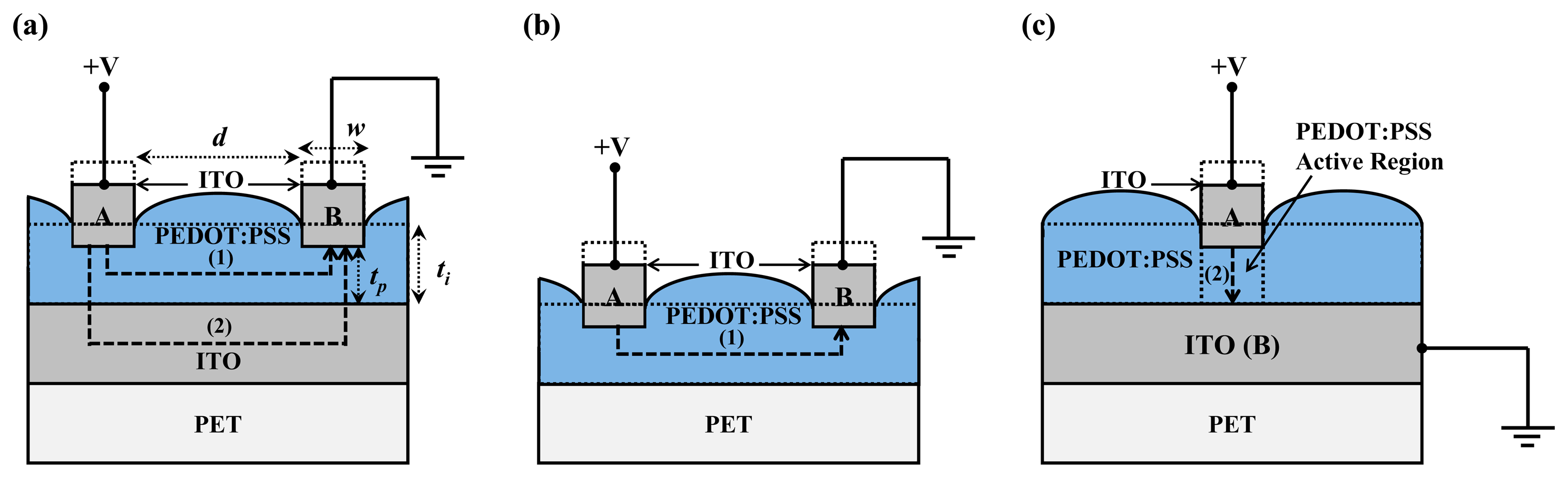
Figure 5 illustrates the conducting mechanism of the PEDOT:PSS pressure sensors with IDE and CPE structures. In Figure 5a, there are two conducting pathways of the IDE structure with b-ITO. Paths (1) and (2) represent the horizontal and vertical conduction within the PEDOT:PSS film, respectively. When a low normal pressure is applied on the PEDOT:PSS film, path (1) is the dominant carrier-conducting pathway and the resistance of this path, R1, increases when the PEDOT:PSS film thickness decreases, i.e., the spin-coating speed increases, as illustrated in Figure 4a. This phenomenon is due to the decrease of the carrier conducting area according to the following equation:
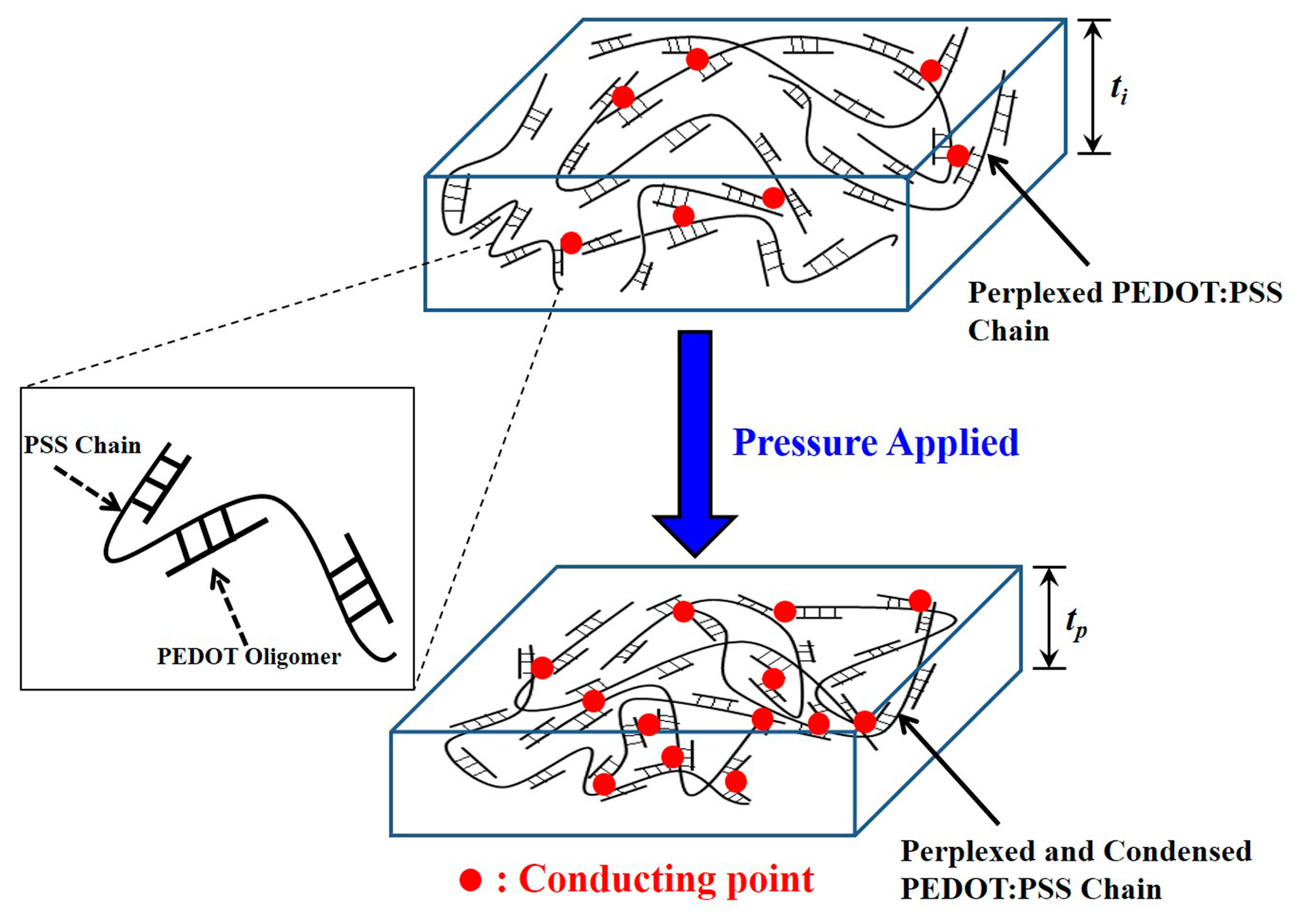
The schematic structures of the PEDOT:PSS films before and after the application of a normal pressure are shown in Figure 6. In this figure, we can observe that the PEDOT oligomers are attached to the long perplexed PSS chain. As we know, the basic conducting mechanism of the PEDOT:PSS film is nearest-neighbor hopping [41,42]. When normal pressure is applied on the film, the perplexed chain of PSS with the attached PEDOTs is condensed from a film thickness of ti to tp [40]. Consequently, the possibility of carrier conduction is increased through the nearest-neighbor and non-nearest-neighbor PEDOT grains due to the reduced distance between PEDOT oligomers or the increased number of conducting points, as indicated by the red points in Figure 6. This leads to the decrease of the resistivity of the PEDOT:PSS film. Therefore, all the piezoresistive pressure sensors exhibit a decreased resistance but different trends in the relation of the PEDOT:PSS film thickness with the applied normal pressure, as shown in Figure 4.
3.3. Relaxation of Piezoresistive Characteristics with Different Structures
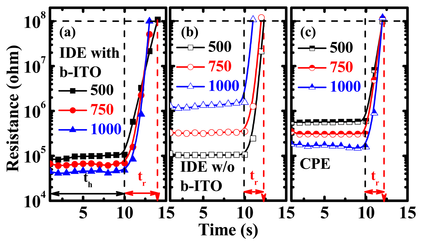
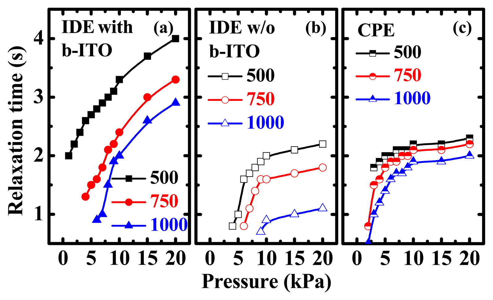
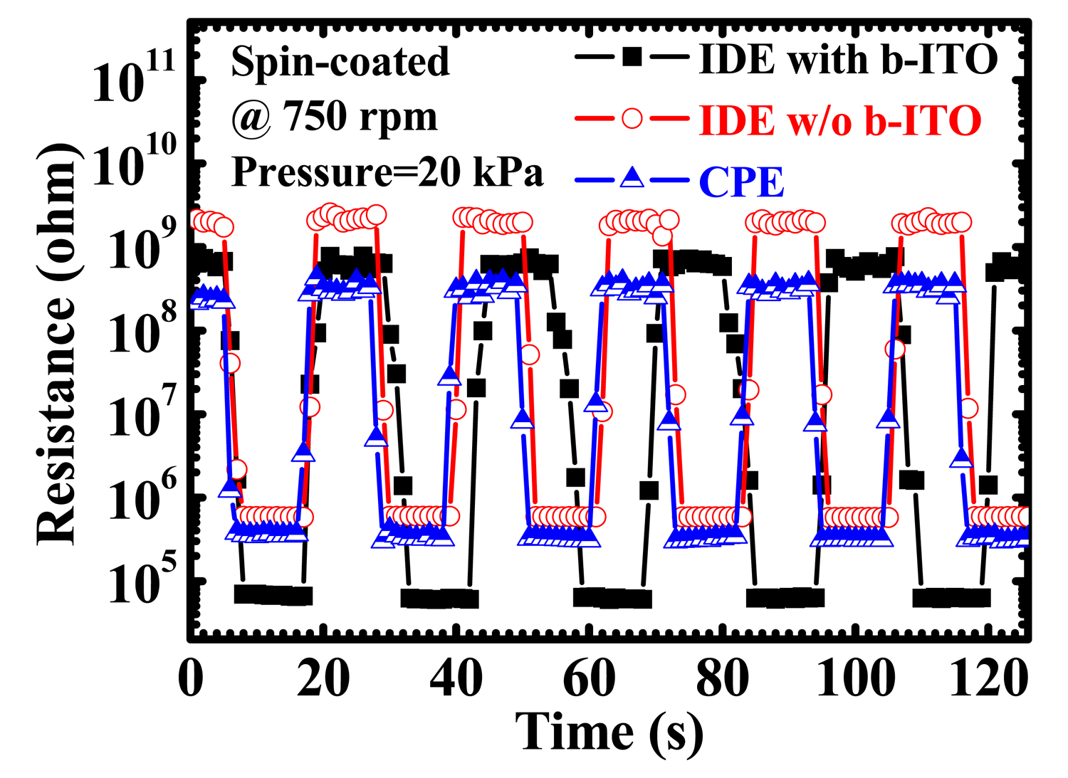
Figure 7 demonstrates the results of reversible testing of the PEDOT:PSS pressure sensors with IDE and CPE structures for at least five loops. A PEDOT:PSS spin-coating speed of 750 rpm and a pressure of 20 kPa applied under a 10-s holding time (th) were used for the measurement. The PEDOT:PSS pressure sensors presented a stable resistive switching for two-minute sequential and reversible operations. To further investigate the response properties, the resistance versus time (R-t) characteristics after the release of pressure of the sensors are displayed in Figure 8. The relaxation time (tr) is defined as the waiting time required to reach the resistance of 100 MΩ after the normal pressure is released. It can be calculated by the following equation:
4. Conclusions
PEDOT:PSS piezoresistive pressure sensors with IDE and CPE structures were studied. The pressure sensors with IDE without b-ITO and with CPE structures showed a carrier conducting mechanism of horizontal and vertical pathways, which is responsible for the piezoresistive characteristic of the IDE pressure sensors with b-ITO at low and high normal pressure. With the combination of two carrier-conducting pathways, the IDE pressure sensors with b-ITO presented high piezoresistive pressure sensitivity. Besides, the decrease of resistance was observed when the normal pressure was applied because of the reduced distance between PEDOT oligomers or the increased number of conducting points within the PEDOT:PSS film. To obtain a stable reversible operation and fast piezoresistive response, a single conducting pathway of pressure sensors with IDE without b-ITO and with CPE structures can be implemented.
Acknowledgments
This work was supported by the Ministry of Science and Technology, R.O.C. under the contract of MOST 103-2221-E-182-061-MY3. The authors would like to thank Mu-Yi Hua and Kin-Fong Lei for their technical support of the PEDOT:PSS solution and the JSV H1000 vertical stand.
Author Contributions
Jer-Chyi Wang designed the study of IDE and CPE structures on piezoresistive characteristics of PEDOT:PSS pressure sensors and did the critical revisions of paper writing. Rajat Subhra Karmakar wrote the paper and contributed to the device fabrication, analysis and interpretation of experimental data. Yu-Jen Lu, Chiung-Yin Huang, and Kuo-Chen Wei provided the concept and clinical application of pressure sensors.
Conflicts of Interest
The authors declare no conflict of interest.
References
- Chatzandroulis, S.; Goustouridis, D.; Normand, P.; Tsoukalas, D. A solid-state pressure-sensing microsystem for biomedical applications. Sens. Actuators A Phys. 1997, 62, 551–555. [Google Scholar]
- Cheng, M.Y.; Lin, C.L.; Lai, Y.T.; Yang, Y.J. A polymer-based capacitive sensing array for normal and shear force measurement. Sensors 2010, 10, 10211–10225. [Google Scholar]
- Fiorillo, A.S. A piezoresistive tactile sensor. IEEE Trans. Instrum. Meas. 1997, 46, 15–17. [Google Scholar]
- Orthnerc, M.P.; Buetefisch, S.; Magda, J.; Rieth, L.W.; Solzbacher, F. Development, fabrication, and characterization of hydrogel based piezoresistive pressure sensors with perforated diaphragms. Sens. Actuators A Phys. 2010, 161, 29–38. [Google Scholar]
- Eaton, W.P.; Smith, J.H. Micromachined pressure sensors: Review and recent developments. Smart Mater. Struct. 1997, 6, 530–539. [Google Scholar]
- Blasquez, G.; Chauffleur, X.; Pons, P.; Douziech, C.; Favaro, P.; Menini, P. Intrinsic thermal behaviour of capacitive pressure sensors: Mechanisms and minimisation. Sens. Actuators A Phys. 2000, 85, 65–69. [Google Scholar]
- Tressler, J.F.; Alkoy, S.; Newnham, R.E. Piezoelectric sensors and sensor materials. J. Electroceram. 1998, 2, 257–272. [Google Scholar]
- Barlian, A.A.; Park, W.T.; Mallon, J.R., Jr.; Rastegar, A.J.; Pruitt, B.L. Review: Semiconductor piezoresistance for microsystems. IEEE Proc. 2009, 97, 513–552. [Google Scholar]
- Tudor, M.J.; Beeby, S.P. Automotive pressure sensors. In Automotive Sensors; Turner, J., Ed.; Momentum Press: New York, NY, USA, 2009; pp. 37–84. [Google Scholar]
- Chiolerio, A.; Roppolo, I.; Sangermano, M. Radical diffusion engineering: Tailored nanocomposite materials for piezoresistive inkjet printed strain measurement. RSC Adv. 2013, 3, 3446–3452. [Google Scholar]
- Shirakawa, H.; Louis, E.J.; Macdiarmid, A.G.; Chiang, C.K.; Heeger, A.J. Synthesis of electrically conducting organic polymers: Halogen derivatives of polyacetylene, (CH)x. J. Chem. Soc. Chem. Commun. 1977, 16, 578–580. [Google Scholar]
- Shirakawa, H. Nobel Lecture: The discovery of polyacetylene film—The dawning of an era of conducting polymers. Rev. Mod. Phys. 2001, 73, 713–718. [Google Scholar]
- Skotheim, T.; Reynolds, J. Handbook of Conducting Polymers, 3rd ed.; CRC Press: New York, NY, USA,, 2007. [Google Scholar]
- Gardner, J.W.; Bartlett, P.N. Application of conducting polymer technology in Microsystems. Sens. Actuators A Phys. 1997, 51, 57–66. [Google Scholar]
- Kanoun, O.; Müller, C.; Benchirouf, A.; Sanli, A.; Dinh, T.N.; Al-Hamry, A.; Bu, L.; Gerlach, C.; Bouhamed, A. Flexible carbon nanotube films for high performance strain sensors. Sensors 2014, 14, 10042–10071. [Google Scholar]
- Takano, T.; Masunaga, H.; Fujiwara, A.; Okuzaki, H.; Sasaki, T. PEDOT nanocrystal in highly conductive PEDOT:PSS polymer films. Macromolecules 2012, 45, 3859–3865. [Google Scholar]
- Latessa, G.; Brunetti, F.; Reale, A.; Saggio, G.; Carlo, A.D. Piezoresistive behaviour of flexible PEDOT:PSS based sensors. Sens. Actuators B Chem. 2009, 139, 304–309. [Google Scholar]
- Bhansali, U.S.; Khan, M.A.; Alshareef, H.N. Electrical performance of polymer ferroelectric capacitors fabricated on plastic substrate using transparent electrodes. Org. Electron. 2012, 13, 1541–1545. [Google Scholar]
- Kirchmeyer, S.; Reuter, K. Scientific importance, properties and growing applications of poly(3,4-ethylenedioxythiophene). J. Mater. Chem. 2005, 15, 2077–2088. [Google Scholar]
- Wang, G.-F.; Tao, X.-M.; Wang, R.-X. Fabrication and characterization of OLEDs using PEDOT:PSS and MWCNT nanocomposites. Compos. Sci. Technol. 2008, 68, 2837–2841. [Google Scholar]
- Xue, F.; Su, Y.; Varahramyan, K. Modified PEDOT-PSS conducting polymer as S/D electrodes for device performance enhancement of P3HT TFTs. IEEE Trans. Electron Devices 2005, 52, 1982–1987. [Google Scholar]
- Hu, Z.; Zhang, J.; Zhu, Y. Effects of solvent-treated PEDOT:PSS on organic photovoltaic devices. Renew. Energy 2014, 62, 100–105. [Google Scholar]
- Chiolerio, A.; Rivolo, P.; Porro, S.; Stassi, S.; Ricciardi, S.; Mandracci, P.; Canavese, G.; Bejtka, K.; Pirri, C.F. Inkjet-printed PEDOT:PSS electrodes on plasma-modified PDMS nanocomposites: Quantifying plasma treatment hardness. RSC Adv. 2014, 4, 51477–51485. [Google Scholar]
- Lang, U.; Rust, P.; Dual, J. Towards fully polymeric MEMS: Fabrication and testing of PEDOT/PSS strain gauges. Microelectron. Eng. 2008, 85, 1050–1053. [Google Scholar]
- Trifigny, N.; Kelly, F.M.; Cochrane, C.; Boussu, F.; Koncar, V.; Soulat, D. PEDOT:PSS-based piezo-resistive sensors applied to reinforcement glass fibres for in situ measurement during the composite material weaving process. Sensors 2013, 13, 10749–10764. [Google Scholar]
- Someya, T.; Sakurai, T. Integration of organic field-effect transistors and rubbery pressure sensors for artificial skin applications. Proceedings of the IEEE International Electron Devices Meeting, Washington, DC, USA,, 8–10 December 2003; pp. 203–206.
- Li, Y.; Deng, C.; Yang, M. A novel surface acoustic wave-impedance humidity sensor based on the composite of polyaniline and poly(vinyl alcohol) with a capability of detecting low humidity. Sens. Actuators B Chem. 2012, 165, 7–12. [Google Scholar]
- Zou, Z.; Kai, J.; Rust, M.J.; Han, J.; Ahn, C.H. Functionalized nano interdigitated electrodes arrays on polymer with integrated microfluidics for direct bio-affinity sensing using impedimetric measurement. Sens. Actuators A Phys. 2007, 136, 518–526. [Google Scholar]
- Mamishev, A.V.; Sundara-Rajan, K.; Yang, F.; Du, Y.; Zahn, M. Interdigital sensors and transducers. IEEE Proc. 2004, 92, 808–845. [Google Scholar]
- Fasth, C.; Fuhrer, A.; Bjork, M.; Samuelson, L. Tunable double quantum dots in InAs nanowires defined by local gate electrodes. Nano Lett. 2005, 5, 1487–1490. [Google Scholar]
- Kang, B.S.; Ahn, S.E.; Lee, M.J.; Stefanovich, G.; Kim, K.H.; Xianyu, W.X.; Lee, C.B.; Park, Y.S.; Baek, I.G.; Park, B.H. High-current-density CuOx/InZnOx thin-film diodes for cross-point memory applications. Adv. Mater. 2008, 20, 3066–3069. [Google Scholar]
- Mandapati, R.; Borkar, A.S.; Srinivasan, V.S.S.; Bafna, P.; Karkare, P.; Lodha, S.; Ganguly, U. The impact of n-p-n selector-based bipolar RRAM cross-point on array performance. IEEE Trans. Electron Device. 2013, 60, 3385–3392. [Google Scholar]
- Wang, H.; Zhou, D.; Cao, J. Development of a skin-like tactile sensor array for curved surface. IEEE Sens. J. 2014, 14, 55–61. [Google Scholar]
- Park, C.-S.; Park, J.; Lee, D.-W. A piezoresistive tactile sensor based on carbon fibers and polymer substrates. Microelectron. Eng. 2009, 86, 1250–1253. [Google Scholar]
- Hillebrandt, H.; Wiegand, G.; Tanaka, M.; Sackmann, E. High electric resistance polymer/lipid composite films on indium-tin-oxide electrodes. Langmuir 1999, 15, 8451–8459. [Google Scholar]
- Hillebrandt, H.; Tanaka, M. Electrochemical characterization of self-assembled alkylsiloxane monolayers on indium-tin oxide (ITO) semiconductor electrodes. J. Phys. Chem. B 2001, 105, 4270–4276. [Google Scholar]
- Kim, H.; Lee, J.; Park, C. Surface characterization of O2-plasma-treated indium-tin-oxide (ITO) anodes for organic light-emitting-device applications. J. Korean Phys. Soc. 2002, 41, 395–399. [Google Scholar]
- Lefebvre, M.; Qi, Z.; Rana, D.; Pickup, P.G. Chemical synthesis, characterization, and slectrochemical studies of poly(3,4-ethylenedioxythiophene)/poly(styrene-4-sulfonate) composites. Chem. Mater. 1999, 11, 262–268. [Google Scholar]
- Qi, Z.; Pickup, P.G. High performance conducting polymer supported oxygen reduction catalysts. Chem. Commun. 1998, 21, 2299–2300. [Google Scholar]
- Lee, Y.-Y.; Lee, J.-H.; Cho, J.-Y.; Kim, N.-R.; Nam, D.-H.; Choi, I.-S.; Nam, K.T.; Joo, Y.-C. Stretching-induced growth of PEDOT-rich cores: A new mechanism for strain-dependent resistivity change in PEDOT:PSS films. Adv. Funct. Mater. 2013, 23, 4020–4027. [Google Scholar]
- Nardes, A.M.; Kemerink, M.; Janssen, R.A.J.; Bastiaansen, J.A.M.; Kiggen, N.M.M.; Langeveld, B.M.W.; van Breemen, A.J.J.M.; de Kok, M.M. Microscopic understanding of the anisotropic conductivity of PEDOT:PSS thin films. Adv. Mater. 2007, 19, 1196–1200. [Google Scholar]
- Vitoratos, E.; Sakkopoulos, S.; Dalas, E.; Paliatsas, N.; Karageorgopoulos, D.; Petraki, F.; Kennou, S.; Choulis, S.A. Thermal degradation mechanisms of PEDOT:PSS. Org. Electron. 2009, 10, 61–66. [Google Scholar]


| Parameters | Structures of Piezoresistive Pressure Sensors | ||
|---|---|---|---|
| IDE with b-ITO | IDE w/o b-ITO | CPE | |
| ITO thickness (μm) | 0.35 | 0.35 | 0.35 |
| PEDOT:PSS thickness (μm) | 0.87–1.88 | 0.87–1.88 | 0.87–1.88 |
| Electrode width (μm) | 500 | 500 | 3000 |
| Electrode spacing (μm) | 500 | 500 | - |
| Cell area (μm2) | 108 | 108 | 9 × 10⁶ |
© 2015 by the authors; licensee MDPI, Basel, Switzerland. This article is an open access article distributed under the terms and conditions of the Creative Commons Attribution license ( http://creativecommons.org/licenses/by/4.0/).
Share and Cite
Wang, J.-C.; Karmakar, R.S.; Lu, Y.-J.; Huang, C.-Y.; Wei, K.-C. Characterization of Piezoresistive PEDOT:PSS Pressure Sensors with Inter-Digitated and Cross-Point Electrode Structures. Sensors 2015, 15, 818-831. https://doi.org/10.3390/s150100818
Wang J-C, Karmakar RS, Lu Y-J, Huang C-Y, Wei K-C. Characterization of Piezoresistive PEDOT:PSS Pressure Sensors with Inter-Digitated and Cross-Point Electrode Structures. Sensors. 2015; 15(1):818-831. https://doi.org/10.3390/s150100818
Chicago/Turabian StyleWang, Jer-Chyi, Rajat Subhra Karmakar, Yu-Jen Lu, Chiung-Yin Huang, and Kuo-Chen Wei. 2015. "Characterization of Piezoresistive PEDOT:PSS Pressure Sensors with Inter-Digitated and Cross-Point Electrode Structures" Sensors 15, no. 1: 818-831. https://doi.org/10.3390/s150100818