A High-Sensitivity Current Sensor Utilizing CrNi Wire and Microfiber Coils

Abstract
: We obtain an extremely high current sensitivity by wrapping a section of microfiber on a thin-diameter chromium-nickel wire. Our detected current sensitivity is as high as 220.65 nm/A2 for a structure length of only 35 μm. Such sensitivity is two orders of magnitude higher than the counterparts reported in the literature. Analysis shows that a higher resistivity or/and a thinner diameter of the metal wire may produce higher sensitivity. The effects of varying the structure parameters on sensitivity are discussed. The presented structure has potential for low-current sensing or highly electrically-tunable filtering applications.1. Introduction
Optical fiber current sensors have been extensively studied due to their characteristics such as immunity to electromagnetic interference, inherent safety, and low weight, compared with traditional electric sensors. Previously, many fiber current sensors have been realized by the use of magneto-optics interaction effects, such as Faraday rotation or magnetostrictive effects. Nevertheless, the Verdet constant of silica fiber is very low and thereby the formed fiber architecture is normally huge [1]. Doping the silica fiber with some rare elements such as terbium or europium can enhance the magneto-optics efficiency of the structure to a great extent and thus the electric-current responsivity may be improved, but the manufacturing cost increases and the temperature cross-sensitivity may be enhanced as well. Another selectable method is to coat a fiber Bragg grating section with a thin conductive metallic material [2]. The current flowing in the coating on the surface of fiber can induce a temperature variation and hence shift the resonant Bragg wavelength. However the fabrication requires the use of the state-of-the-art coating equipment.
Recently, microfiber devices with sub-wavelength scales have attracted great interest because of their compactness, high flexibility, and large evanescent field effect [3,4]. Using the self-coupling effect of the adjacent microfibers, a number of resonators with microfiber loops [5], knots [6], and coils [7,8] have been realized, which may produce very low transmission losses and high Q values [7,8]. It has been found that when a copper rod is surrounded with a microfiber loop resonator, the dip wavelength can be shifted by the applying current [9]. This finding opens a possibility of electric current sensing utilizing the temperature variation in a metal-microfiber structure. The sensitivity is defined as the wavelength shift per unit change of the square of current. So far the realized sensitivity is 0.0265–7.5 nm/A2 within a typical current range of 0–2 A [9–13]. In this work, a very high sensitivity is achieved with assistance of a thin chromium-nickel (CrNi) wire and a microfiber coil resonator. The measured sensitivity is as high as 220.65 nm/A2, which is two orders of magnitude higher than other metal-microfiber configurations described in the literature, thus exhibiting great potential for high-sensitivity current sensing or electrically tunable filtering applications.
2. Experimental Setup
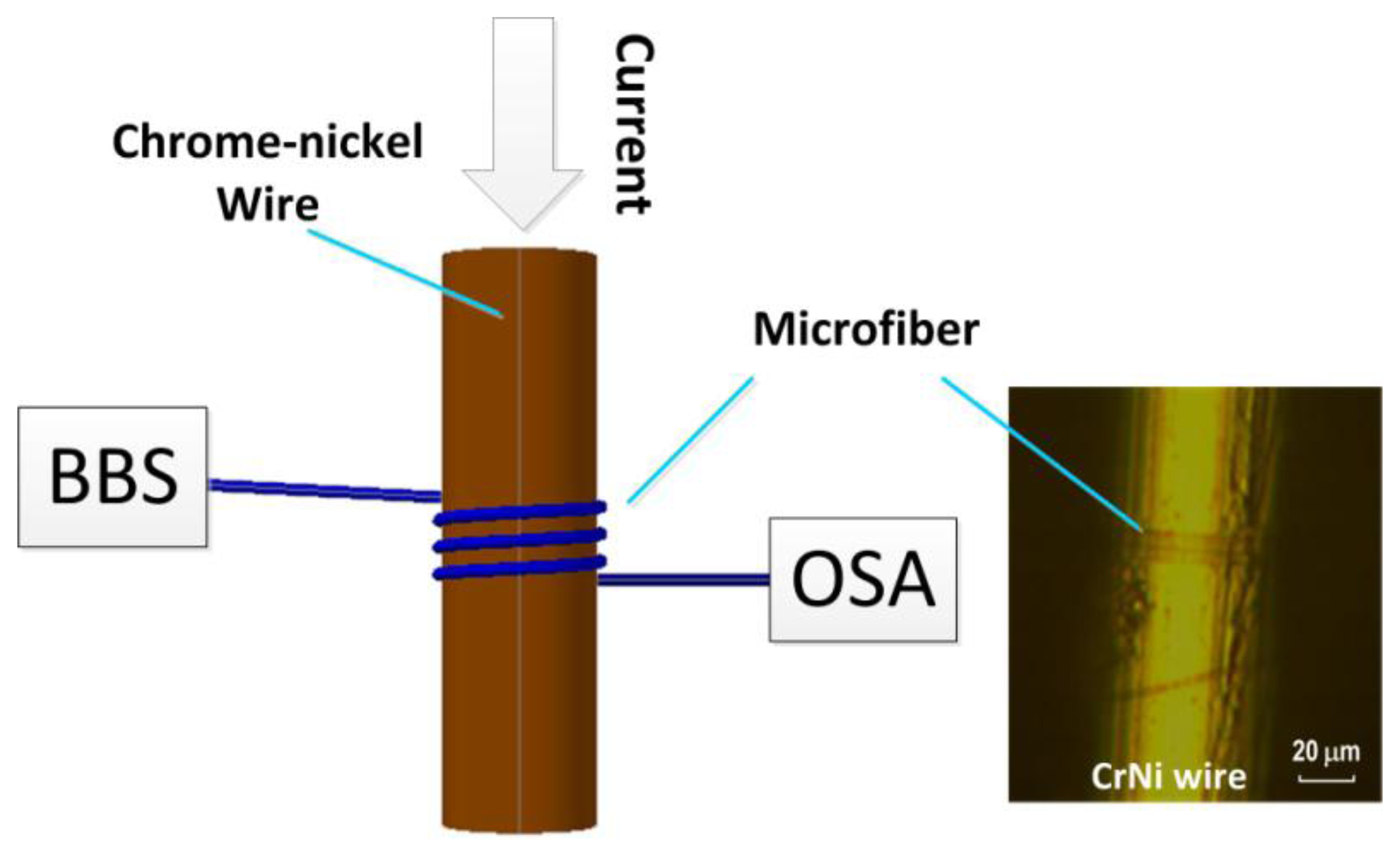
Figure 1 shows the configuration of our electric current meter, which contains a subwavelength-scale microfiber spirally wrapped around a non-magnetic chromium-nickel (CrNi) wire. The microfiber is obtained by locally heating and stretching a standard single-mode fiber with assistance of the conventional flame-brushing technique [4]. The fiber diameter is tapered to 2–6 μm by controlling the fiber stretching speed. Like the well-established biconical model [4], the tapered fiber comprises two transition regions on both ends and a minimum waist in the center. We subsequently wrap the uniform waist onto the CrNi wire that contains 20% chromium and 80% nickel. To do so, we mount the CrNi wire onto a precision rotational stage as described in [8]. The microfiber may be wrapped around the metal wire when one fiber end is fixed on the rotational stage and another one end is pulled straight. In our experiments the spacing between adjacent microfiber turns can be changed slightly by tuning the pulling force. The spacing of two adjacent microfibers turns is no more than 4 μm, which can produce strong mode coupling of the microfibers. The adopted CrNi-wire diameters are 50 μm, 60 μm, and 80 μm, respectively. Thanks to the strong van der Waals and the electrostatic attraction forces between the microfiber and the metal wire, the device is relatively stable and robust.
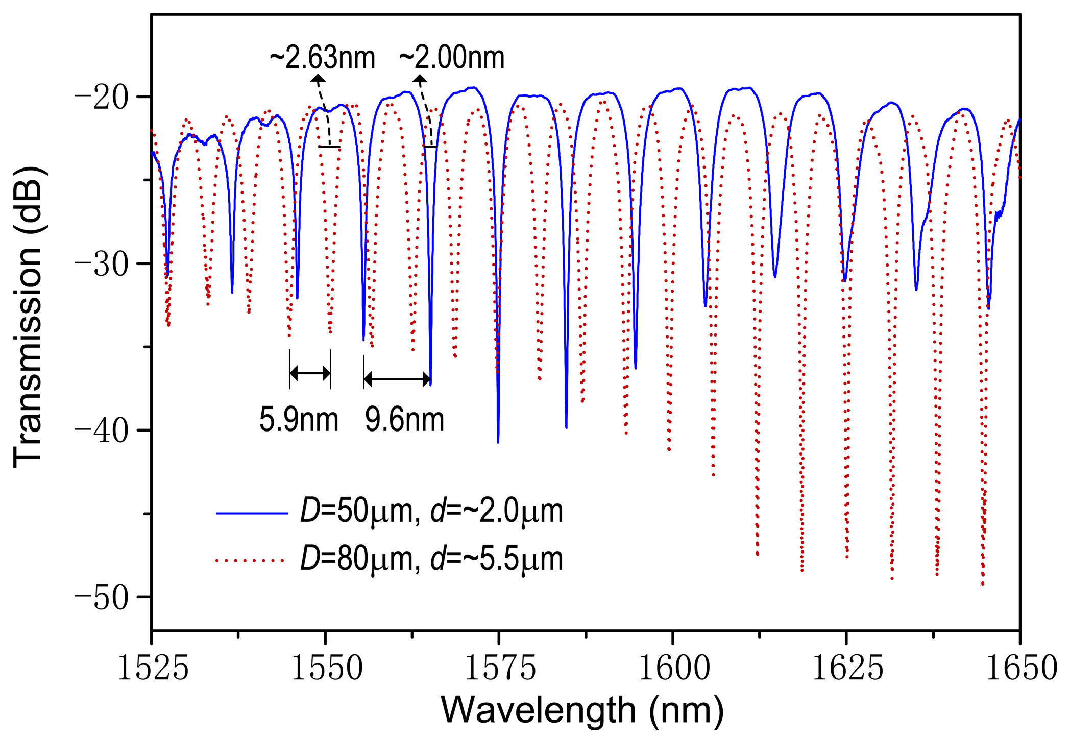
Figure 2 records the transmission spectra for the metal-wire diameters of D = 50 μm and 80 μm and the microfiber diameters of d = ∼2.0 μm and ∼5.5 μm, respectively, measured using a broad-band light source (BBS) and an optical spectrum analyzer (OSA). As shown in Figure 1, the input mode field experiences self-coupling between microfibers through the evanescent mode field and thus the resonant spectrum occurs at the microfiber output. The free spectral range (FSR) is mostly dependent on the diameter of the CrNi wire. A larger value of D may generate a wider FSR. From Figure 2, the measured FSRs are about 9.60 nm and 5.90 nm and the estimated full-widths at half-maximum are ∼2.00 nm and ∼2.63 nm, corresponding to the thinner and thicker metal wires, respectively. Note that the spectral characteristics can be optimized by tuning the number of microfiber coils around the metal wire. In our experiment, the coil number used is four, which gives a compact device length of less than 35 μm. The extinction ratio of spectrum can be higher than 20 dB from Figure 2. The transmission loss is around 20 dB, which is acceptable for electric current measurements. Our investigation also shows that for a microfiber diameter of ∼5 μm, each loop of microfiber coil may produce a loss increment of around 5.0–7.0 dB, mainly due to the absorption of the metal material.
3. Results and Discussion
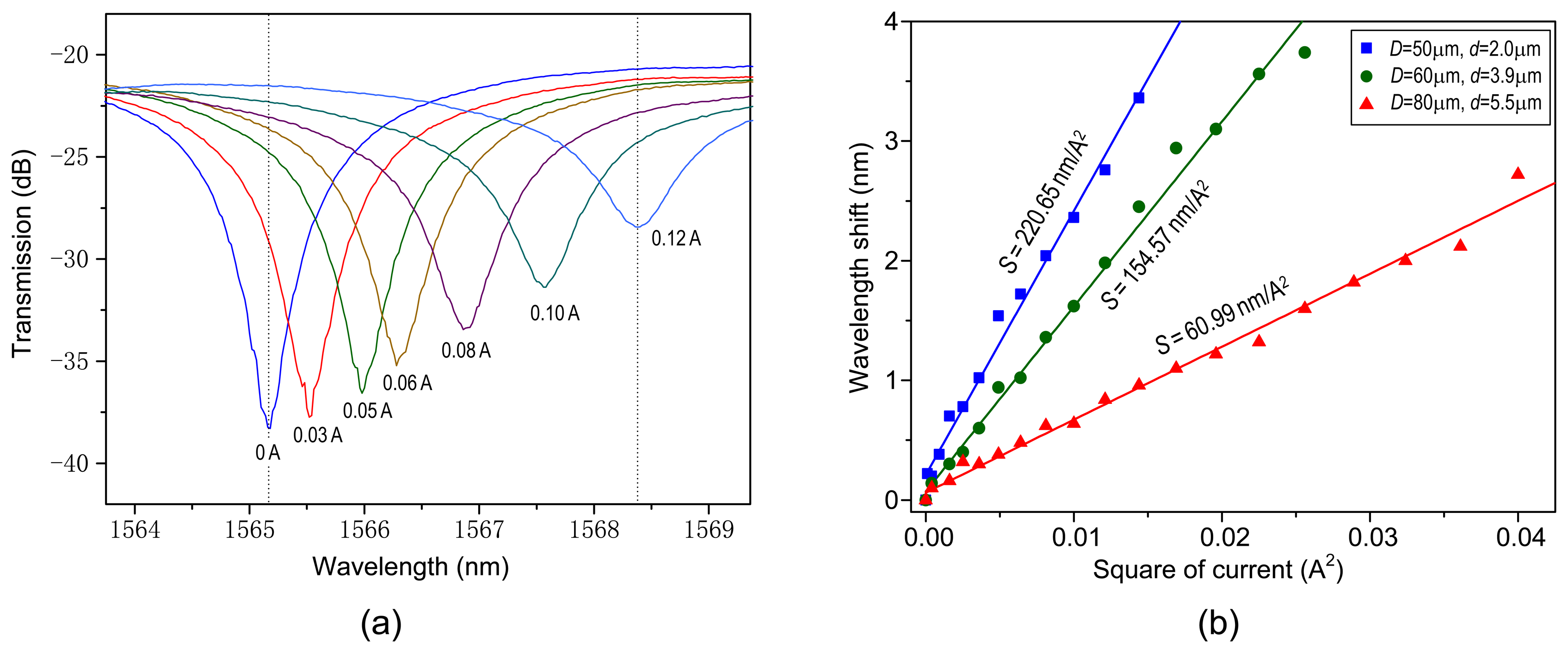
Figure 3a illustrates the transmission spectra at different electric currents, for the parameters D = 50 μm and d = 2.0 μm at the room temperature. The dip wavelength redshifts from 1,565.2 nm to 1,568.4 nm when the applied current increases from 0 to 0.12 A, which produces a sensitivity of around 220.65 nm/A2. Figure 3b details the dip wavelengths as a function of the square of current, for the parameters D/d = 50 μm/∼2.0 μm, 60 μm/∼3.9 μm, and 80 μm/∼5.5 μm, respectively, around 1,565 nm. The points are the experimental data and the solid lines are the linear fitting results.
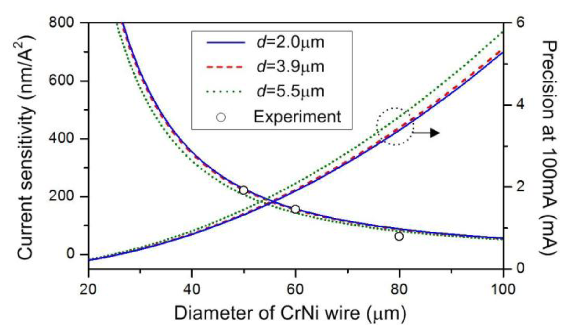
We can see that the wavelengths increase almost linearly with an increase in the square of current. The wavelengths are measured with a current increment of 0.01 A at each step. As the current varies, the dip wavelength shifts promptly and becomes steady within about one minute. From Figure 3b, our measured sensitivities are 220.65 nm/A2, 154.57 nm/A2, and 60.99 nm/A2, respectively. In fact, the smaller D or d may be ready to generate the larger sensitivity, as detailed later. As shown in Figure 3b, the maximum currents are 0.12 A, 0.16 A, and 0.20 A, respectively. A too large current should be avoided because a very high temperature may soften the silica microfiber and thus induce an irreversible variation in the spectrum. In a proper current range, our structure exhibits good repeatability and reconfigurability, making it appropriate for low-current sensing or electrically tunable filtering. Table 1 indicates electric-current responsivities of the metal-microfiber structures recently reported in the literature. The measured sensitivity has been improved by over two orders of magnitude compared to those other configurations. The precision is defined as the minimum current variation that can be detected in the OSA. Considering a wavelength resolution of OSA, δλ, the precision can be expressed as δI = δλ/(dλ/dI) = δλ/(2I·S). It is obvious that the precision is mainly determined by the sensitivity and the resolution of OSA. Giving S = 220.65 nm/A2 and δλ = 0.06 nm for our OSA, we obtain δI = 1.36 mA at 100 mA.
To investigate the influence of physical parameter to the current sensitivity, we note that the dissipated power from the carrying electric current in the conduction wire can give rise to an instantaneous temperature variation ΔT, with the relationship of ΔT = (Kρh/σ)·ΔI2 [5,6], where K is the constant of dissipation, ΔI2 is the change of the square of current, ρ is the resistivity of the metal wire, h is the structural length, and σ is the cross-sectional area of the metal wire. The temperature variation can influence the effective index neff and the length L of each microfiber coil and hence shift the transmission spectrum. In a microfiber resonator, the resonant condition is given by neffL = m·λres, with neff the effective index and m an integer. Then the wavelength shift Δλ can be expressed as:
4. Conclusions
In conclusion, we report a high-sensitivity electric current sensor manufactured by wrapping a microfiber onto a thin-diameter CrNi wire. The measured current sensitivity can be as high as 220.65 nm/A2 for a device length of only 35 μm. Such a sensitivity is two orders of magnitude higher than other metal-microfiber configurations reported in the literature. Considering a 0.06 nm resolution in the OSA, the detectable precision is ∼1.36 mA around 100 mA. The effects of varying the component sizes on the device sensitivity are discussed. The experimental results show good agreement with the theoretical analysis. The presented device exhibits potential for low-current sensing or electrically-tunable filtering applications.
Acknowledgments
This work is supported by the National Science Found for Distinguished Young Scholars of China (61225023), the National Natural Science Foundation of China (61177074, 11004085, and 11104117), the Project of Science and Technology New Star of Zhujiang in Guangzhou city (2012J2200062), the Planned Science and Technology Project of Guangzhou (2012J5100028), and the Guangdong Natural Science Foundation (S2013030013302).
Conflicts of Interest
The authors declare no conflict of interest.
References
- Ning, Y.N.; Wang, Z.P.; Palmer, A.W.; Grattan, K.T.V.; Jackson, D.A. Recent progress in optical current sensing techniques. Rev. Sci. Instrum. 1995, 66, 3097–3111. [Google Scholar]
- Cavaleiro, P.M.; Araujo, F.M.; Ribeiro, A.B.L. Metal-coated fibre Bragg grating sensor for electric current metering. Electron. Lett. 1998, 34, 1133–1135. [Google Scholar]
- Tong, L.M.; Gattass, R.R.; Ashcom, J.B.; He, S.L.; Lou, J.Y.; Shen, M.Y.; Maxwell, I.; Mazur, E. Subwavelength-diameter silica wires for low-loss optical wave guiding. Nature 2003, 426, 816–819. [Google Scholar]
- Tong, L.M.; Lou, J.Y.; Mazur, E. Single-mode guiding properties of subwavelength-diameter silica and silicon wire waveguides. Opt. Express 2004, 12, 1025–1035. [Google Scholar]
- Tong, L.M.; Guo, X. Supported microfiber loops for optical sensing. Opt. Express 2008, 16, 14429–14434. [Google Scholar]
- Jiang, X.S.; Tong, L.M.; Guillaume, V.; Guo, X.; Tsao, A.; Qing, Y.; Yang, D. Demonstration of optical microfiber knot resonators. Appl. Phys. Lett. 2006, 88. [Google Scholar] [CrossRef]
- Xu, F.; Brambilla, G. Embedding optical microfiber coil resonators in Teflon. Opt. Lett. 2007, 32, 2164–2166. [Google Scholar]
- Jung, Y.M.; Murugan, G.S.; Brambilla, G.; Richardson, D.J. Embedded optical microfiber coil resonator with enhanced high-Q. IEEE Photon. Technol. Lett. 2010, 22, 1638–1640. [Google Scholar]
- Guo, X.; Li, Y.H.; Jiang, X.S.; Tong, L.M. Demonstration of critical coupling in microfiber loops wrapped around a copper rod. Appl. Phys. Lett. 2007, 91. [Google Scholar] [CrossRef]
- Lim, K.S.; Harun, S.W.; Damanhuri, S.S.A.; Jasim, A.A.; Tio, C.K.; Ahmad, H. Current sensor based on microfiber knot resonator. Sens. Actuators A Phys. 2011, 167, 60–62. [Google Scholar]
- Sulaiman, A.; Harun, S.W.; Aryanfar, I.; Ahmad, H. DC current sensing capability of microfibre Mach-Zehnder interferometer. Electron. Lett. 2012, 48, 943–945. [Google Scholar]
- Sulaiman, A.; Harun, S.W.; Ahmad, F.; Norizan, S.F.; Ahmad, H. Electrically Tunable Microfiber Knot Resonator Based Erbium-Doped Fiber Laser. IEEE J. Quantum Electron. 2012, 48, 443–446. [Google Scholar]
- Chen, G.Y.; Newson, T.P.; Brambilla, G. Inspection of electrical wires for insulation faults and current surges using sliding temperature sensor based on optical Microfibre coil resonator. Electron. Lett. 2013, 49, 46–47. [Google Scholar]


| Microfiber Structures | Sensitivity |
|---|---|
| Microfiber loop & copper wire | 0.0265 nm/A [9] |
| Microfiber knot & copper rod | 0.0513 nm/A2 [10] |
| Microfiber Mach-Zehnder interferometer & copper wire | 0.54 nm/A2 [11] |
| Erbium-doped microfiber knot & copper wire | 0.70 nm/A2 [12] |
| Microfiber coil & nichrome with Teflon tube | 7.5 nm/A2 [13] |
| Our present device | 220.65nm/A2 |
© 2014 by the authors; licensee MDPI, Basel, Switzerland. This article is an open access article distributed under the terms and conditions of the Creative Commons Attribution license ( http://creativecommons.org/licenses/by/3.0/).
Share and Cite
Xie, X.; Li, J.; Sun, L.-P.; Shen, X.; Jin, L.; Guan, B.-o. A High-Sensitivity Current Sensor Utilizing CrNi Wire and Microfiber Coils. Sensors 2014, 14, 8423-8429. https://doi.org/10.3390/s140508423
Xie X, Li J, Sun L-P, Shen X, Jin L, Guan B-o. A High-Sensitivity Current Sensor Utilizing CrNi Wire and Microfiber Coils. Sensors. 2014; 14(5):8423-8429. https://doi.org/10.3390/s140508423
Chicago/Turabian StyleXie, Xiaodong, Jie Li, Li-Peng Sun, Xiang Shen, Long Jin, and Bai-ou Guan. 2014. "A High-Sensitivity Current Sensor Utilizing CrNi Wire and Microfiber Coils" Sensors 14, no. 5: 8423-8429. https://doi.org/10.3390/s140508423
APA StyleXie, X., Li, J., Sun, L.-P., Shen, X., Jin, L., & Guan, B.-o. (2014). A High-Sensitivity Current Sensor Utilizing CrNi Wire and Microfiber Coils. Sensors, 14(5), 8423-8429. https://doi.org/10.3390/s140508423