Piezoelectric Energy Harvesting Solutions


Abstract
: This paper reviews the state of the art in piezoelectric energy harvesting. It presents the basics of piezoelectricity and discusses materials choice. The work places emphasis on material operating modes and device configurations, from resonant to non-resonant devices and also to rotational solutions. The reviewed literature is compared based on power density and bandwidth. Lastly, the question of power conversion is addressed by reviewing various circuit solutions.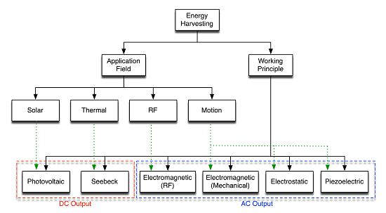
1. Introduction
Energy harvesting or energy scavenging is the process of extracting small amount of energy from ambient environment through various sources of energy. The available energy for harvesting is mainly provided by ambient light (artificial and natural lighting), ambient radio frequency, thermal sources and mechanical sources.
Reduction in size and energetic demands of sensors, and the low power consumption trend in CMOS electronic circuitry opened novel research lines on battery recharge via available power sources. Harvesters can be employed as battery rechargers in various environments, such as industries, houses [1,2], the military (as for unmanned aerial vehicles [3]) and handheld or wearable devices [4–9]. The possibility to avoid replacing exhausted batteries is highly attractive for wireless networks (Wireless Sensor Networks [10]), in which the maintenance costs due to battery check and replacement are relevant. Another emerging field of application is biomedical systems, where the energy could be harvested from an off-the-shelf piezoelectric unit and used to implement drug delivery systems [11] or tactile sensors [12–14]. Recent research also includes energy conversion from the occlusal contact during chewing by means of a piezoelectric layer [11,15] and from heart beats [16].
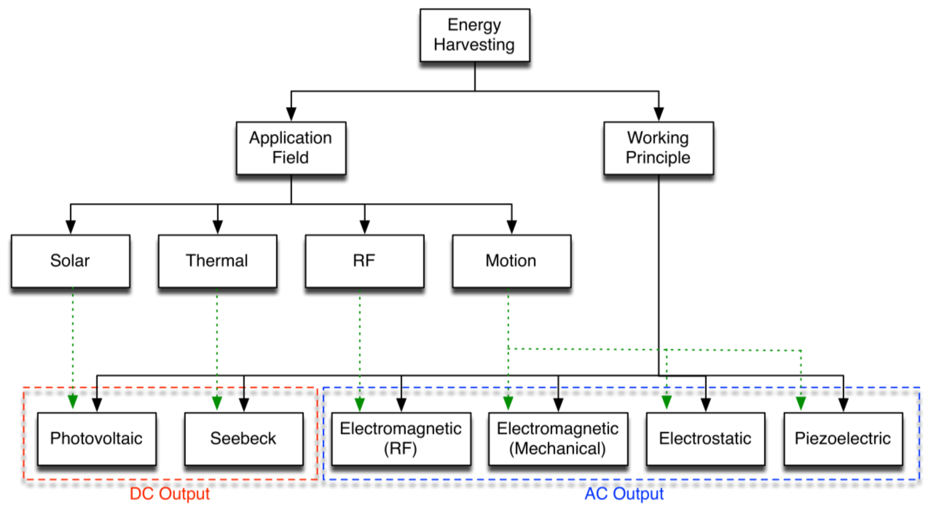
We can classify the main energy harvesting technologies by the hierarchy shown in Figure 1. Motion harvester systems can be structured as follows: the harvester collects inputs through its frame, directly connected to the hosting structure and to the transducer; at the end of the system chain, a conditioning circuit manipulates the electrical signals. This paper specifically focuses on piezoelectric motion harvesting techniques.
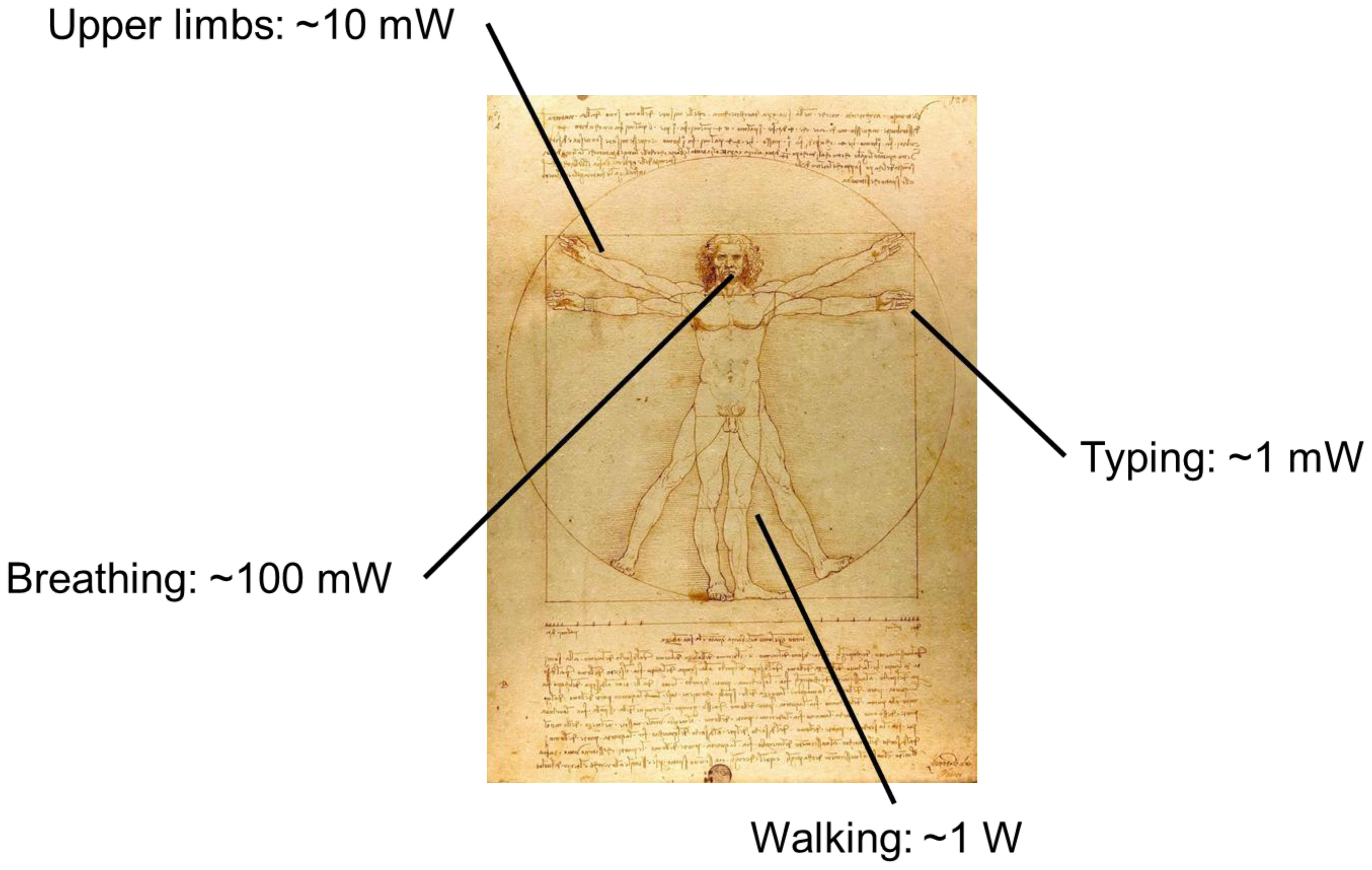
The possibility and the effectiveness of extracting energy from human activities has been under study for years [17]. As a matter of fact, continuous and uninterrupted power can potentially be available: from typing (∼mW), motion of upper limbs (∼10 mW), air exhalation while breathing (∼100 mW), walking (∼W) [18,19] (Figure 2), and in this work we review state of the art of motion based energy harvesting.
Among available motion based harvesting techniques, piezoelectric transduction offers higher power densities [20] in comparison to electrostatic transduction (which also needs an initial polarization). Also, piezoelectric technologies are better suited than electromagnetic ones for MEMS implementation, because of the limitations in magnets miniaturization with current state-of-the-art microfabrication processes [21].
2. Transduction Principle
The piezoelectric effect converts mechanical strain into electric current or voltage. It is based on the fundamental structure of a crystal lattice. Certain crystalline structures have a charge balance with negative and positive polarization, which neutralize along the imaginary polar axis. When this charge balance is perturbed with external stress onto the crystal mesh, the energy is transferred by electric charge carriers creating a current in the crystal. Conversely, with the piezoelectric effect an external charge input will create an unbalance in the neutral charge state causing mechanical stress.
The connection between piezoelectricity and crystal symmetry are closely established. The piezoelectric effect is observed in crystals without center of symmetry, and the relationship can be explained with monocrystal and polycrystalline structures.
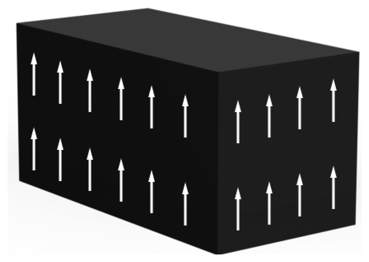
In a monocrystal (Figure 3) the polar axes of all of the charge carriers exhibit one-way directional characteristics. These crystals demonstrate symmetry, where the polar axes throughout the crystal would lie unidirectional even if it was split into pieces.
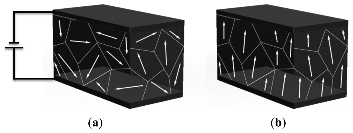
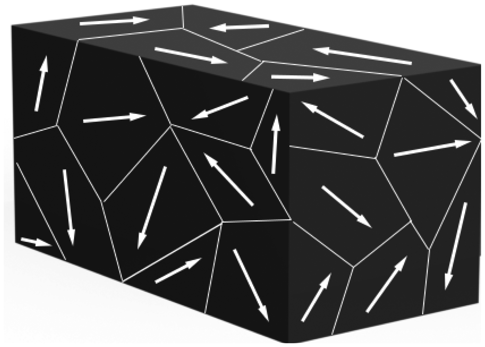
Instead, a polycrystal (Figure 4) is characterized by different regions within the material with different polar axes. It is asymmetrical because there is no point at which the crystal could be cut that would leave the two remaining pieces with the same resultant polar axes.
In order to attain the piezoelectric effect, the polycrystal is heated to the Curie point along with strong electric field. The heat allows the molecules to move more freely and the electric field forces the dipoles to rearrange in accordance with the external field (Figure 5).
As a result, the material possesses piezoelectric effect: a voltage of the same polarity as of the poling voltage appears between electrodes when the material is compressed; and opposite polarity appears when stretched. Material deformation takes place when a voltage difference is applied, and if an AC signal is applied the material will vibrate at the same frequency as the signal [23–25].
Piezoelectricity is governed by the following constitutive equations, which link the stress T, the strain S, the electric field E and the electrical induction D:
For each couple of constitutive equations there is a different piezoelectric coefficient, defined as:
An important parameter is the electromechanical coupling factor, kiq, which describes the conversion between mechanical and electrical energy. It can be written in terms of coefficients of the material:
The efficiency of energy conversion, η, is described, at resonance, as follows:
To understand how the electrical quantities (V and I) are related to the mechanical ones (force F and displacement z), the particular case of a piezoelectric disk can be considered. In this case, from Equation (1) the following relationships can be obtained [28]:
In which the featuring quantities are the restoring force Fp of the piezoelectric material, its stiffness when it is short-circuited kPE, the displacement z, the force factor α, the voltage across the electrodes V and the outgoing current Ip, and the clamped capacitance Cp. These equations are derived considering the following approximations:
In a more generic case of a mechanical stress in direction p and an induced electric field in direction i, the open-circuit voltage of a piezoelectric device can be written as follows:
Assuming that the voltage coefficient gip is constant with the stress, and where l is the gap between the electrodes.
3. Materials
Each piezoelectric material can be characterized with a set of parameters. For example, considering a stress Tp as input, the strain coefficient dip gives the relationship between the applied stress and the electric induction Di (therefore, current density is ), while the voltage coefficient gip gives the voltage Equation (9). Thus, a high energy density piezoelectric material is characterized by a large product of the strain coefficient (dip) and the voltage constant (gip) [29]. The coupling factor kiq, combining the piezoelectric properties of the material with its mechanical and electrical properties, gives the converted energy and efficiency of the harvester, as remarked by Equations (4) and (5). The mechanical characteristics (Young's modulus) define the robustness and toughness of the device and also play an important role in defining piezoelectric coefficients, Equation (3), and coupling factor. Dielectric permittivity also plays a similar role in definitions. All these parameters (determined by the material) are crucial in designing a harvesting system, making in turn material selection a primary factor in piezoelectric harvesters.
Table 1 lists some of the most common piezoelectric materials, mainly piezoceramics (that are polarized ferroelectric ceramics [26]), such as PZT [30] and barium titanate [31]. Out of them, Anton and Sodano [32] and Shen and colleagues [33] report PVDF polymer and micro-fiber composites (MFC) as highly flexible materials. MFCs are composites that combine the energy density of piezoceramic materials with the flexibility of epoxy [34]. In [33], the authors compared PZT with PVDF and MFC, they showed that although PZT shows the highest power density, it is not well suited for high g-vibrations because of its lower yield strength that results in lower robustness, leading to fracture. Furthermore, zinc-oxide (ZnO) is an interesting material that is pushing the piezoelectric field to a nanometric scale. It is used to grow one dimensional hair-like nanowires, with diameters in the sub-one hundred nanometer scale and lengths ranging from several hundreds of nanometers to a few centimeters. Zinc exhibits both semiconductor and piezoelectric properties, it is relatively biosafe and biocompatible, so it can be involved in biomedical applications with little toxicity [35]. In [36] a strain coefficient of ∼10 pC/N was reported for zinc oxide nanowires.
The piezoelectric properties change logarithmically with age allowing them to stabilize. Therefore, manufacturers usually specify the constants of the material after a period of time [21,37]. Table 1 compares a set of piezoelectric materials based on the coefficients related to mechanical input and electrical output.
4. Resonant Devices
Piezoelectric transducers are frequently used in inertial generators. These systems are composed of a fixed reference, which transmits vibrations to an inertial mass located on a mechanical moving part, when an external acceleration is applied. Piezoelectric materials provide transduction, exploiting the mechanical strain occurring in such devices.
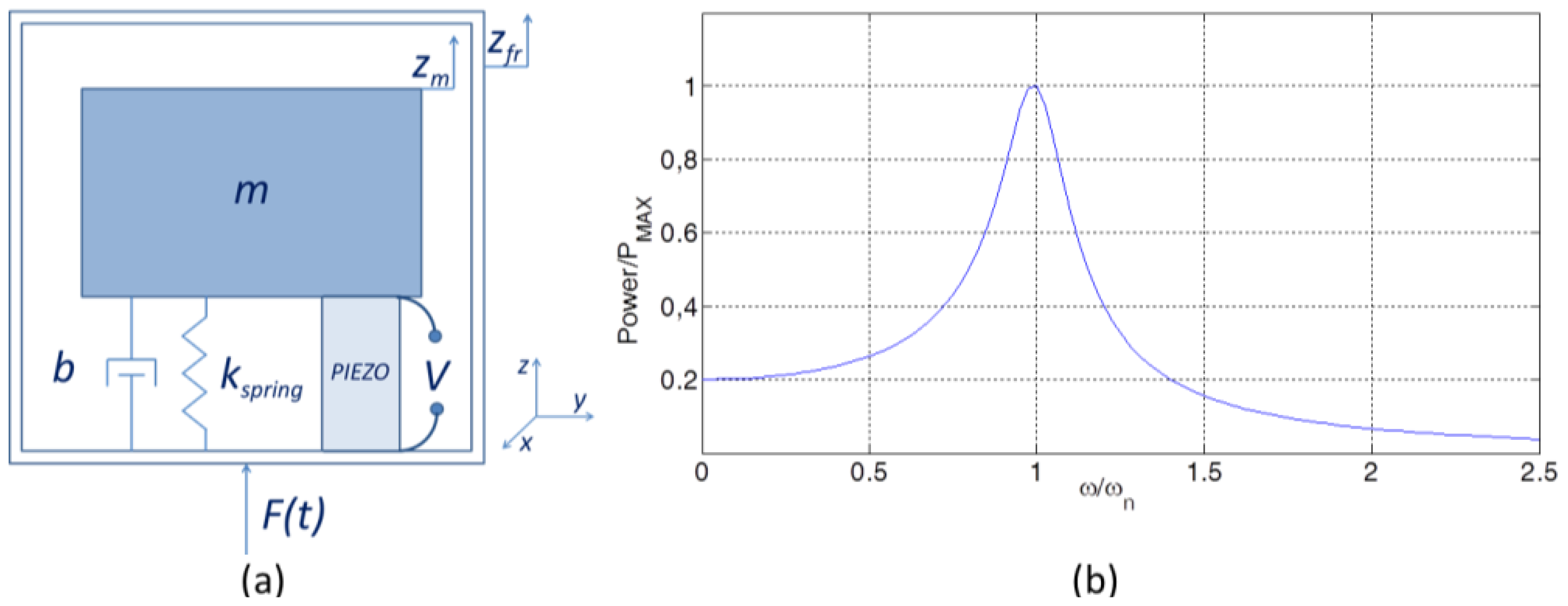
Inertial generators can be described as a second order mass-spring-damper system [29,43–45], along with a piezoelectric element connected parallel to the damper [28] (Figure 6). The system is governed by the following equation of motion:
Such a system is characterized by a natural or resonant angular frequency (ωn) given by:
In practical cases ω has to be designed to match the expected ambient excitation angular frequency (ω). When this happens, the maximum energy is extracted from the transducer (as shown in Figure 6).
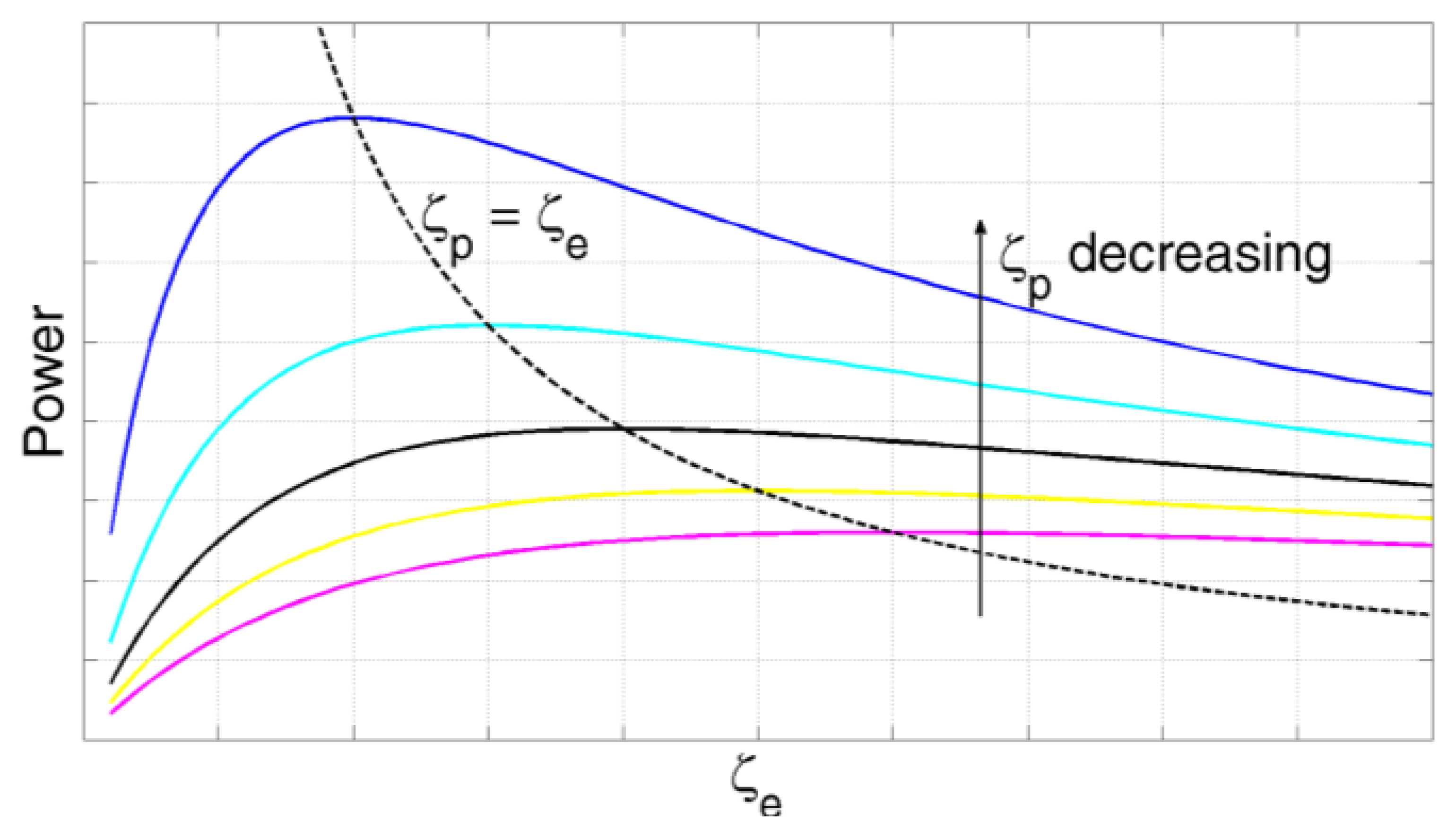
The power that the transducer can extract while working at resonance can be derived solving (8) for zm. The harvested power is obtained by formulating the portion of the power flowing through the damper related to the transducing mechanism [21,45]:
4.1. d31 Mode Generators
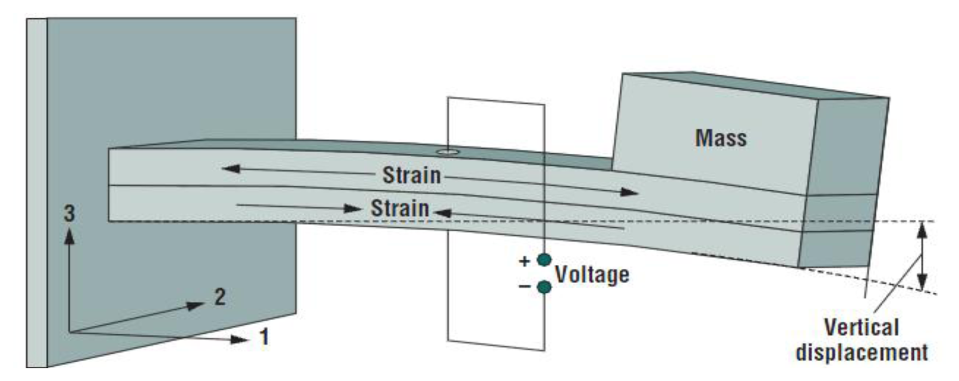
In d31 operating mode the material has an induced electric field in direction 3, as a response to the stress along direction 1. Figure 8 shows the most common configuration of a piezoelectric harvester, which comprises of a rectangular beam, a tip mass and a piezoelectric material.
We can distinguish unimorph and bimorph configurations based on the piezoelectric material presence on top of the beam or on both sides. A thorough comparison of these two configurations was presented by Ng in [48]. The former was described as most suitable for lower frequencies and load resistance, whereas the latter showed optimal functioning at higher frequencies and higher loads, while being able to extract higher amount of power. Indeed, in bimorph cantilever the two piezoelectric pieces undergo opposite strain during operation, and they can be bonded electrically in series (to increase the voltage output) or in parallel (to increase the current output). Lu and colleagues [49] investigated the load resistance effort in case of bimorph cantilevers and pure resistive load. They formulated the following relationship for the optimal load:
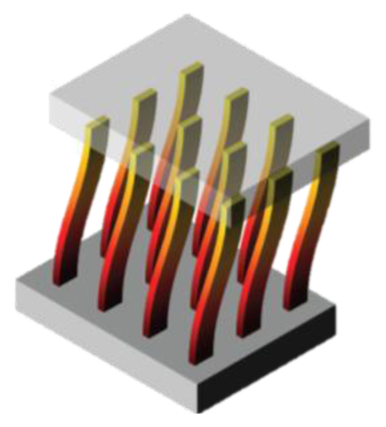
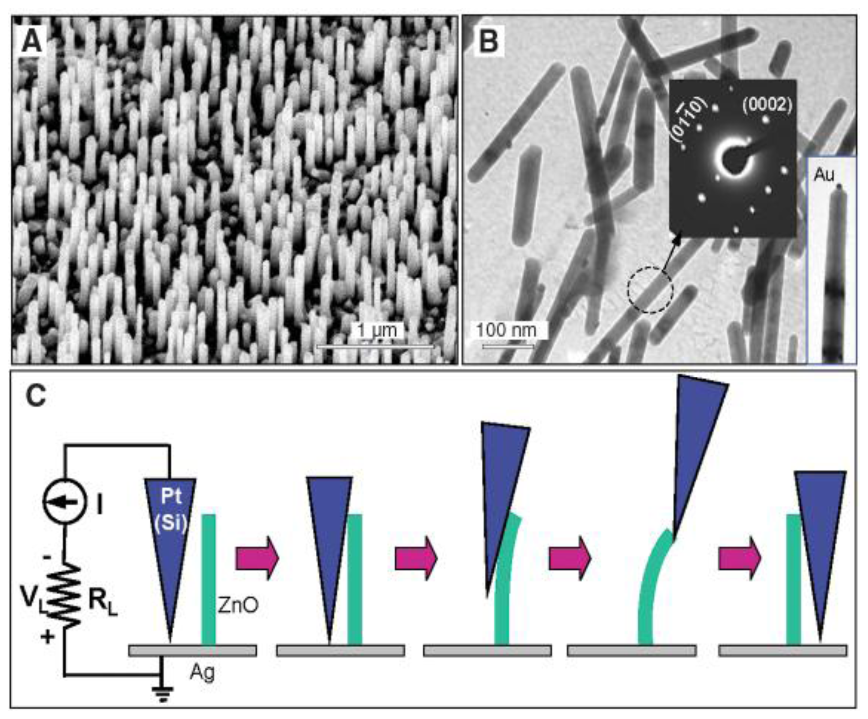
Wang and Song [35] developed a nanogenerator based on a zinc oxide nanowire array (Figure 9A). A silver paste was used as ground contact at the bottom of the nanowires, while the other electrodes were fabricated by means of a Pt film coated on the tip of an atomic force microscope (Figure 9C). Pt was chosen in order to form a Schottky barrier at the interface with ZnO. The barrier allows the nanowire to accumulate charge during the deformation along its length (due to the piezoelectric effect) and discharging it on a load circuit only when the Schottky barrier is forward biased. This happens only during a small portion of the entire cycle, but resulting in a sharper and higher voltage (and power) output. The authors reported conversion efficiency ranging between 17% and 30%, and a typical resonance frequency of ∼10 MHz. Each nanowire is estimated to provide with an output voltage of ∼8 mV and corresponding power of ∼0.5 pW. Considering an array of 20 nanowires per μm2, the output power can be ∼10 pW/μm2.
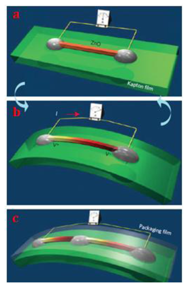
Vertically aligned piezoelectric nanowires may lack in mechanical robustness, lifetime, environmental adaptability and output stability. To overcome such inconveniences, a flexible power generator based on cyclic stretching-releasing mechanism for piezoelectric fine wires was proposed by Yang and colleagues [50]. In this work, a piezoelectric fine wire (PFW) lies flat on a flexible substrate with fixed ends onto the electrodes (Figure 10a). When the substrate is subjected to load, it bends (Figure 10b) inducing a tensile strain of 0.05%–0.1% in the wire. This leads to a drop in the piezoelectric potential along the wire, forcing electrons to flow along an external circuit to charge the wire. When the substrate is released, electrons flow back in the opposite direction. Periodically bending and releasing the PFW therefore generates an alternating current. Generators based on multiple PFWs can be integrated to raise the output voltage.
4.2. d33 Mode Generators
In d33 operating mode the material is subjected to a stress in the same direction of the produced electric field. This operating mode led initially to impact harvesters [51–55], while vibrating generators were made only via d31 effect. However, several researchers focused on fabricating vibrating devices with alternative modes to d31. This research line is motivated by the fact that piezoelectric coefficients in d33 and d15 modes are higher than d31 ones (Table 1), so this can possibly lead to devices with higher output power. d33 vibrating generators can be used, for example, in industrial fields such as automotive and machinery or wherever there are mechanical joints that, due to tolerances, show relative movements between structural components. The cyclical movement of structures, due for example to the effect induced by the vibrational dynamics of the system, can be exploited by adopting appropriate mechatronic systems. Thanks to their geometry and to their structure, the mechanism is able to convert macroscopic displacement (in the order of millimeters) into a high force microscopic motion acceptable by the piezoelectric material.
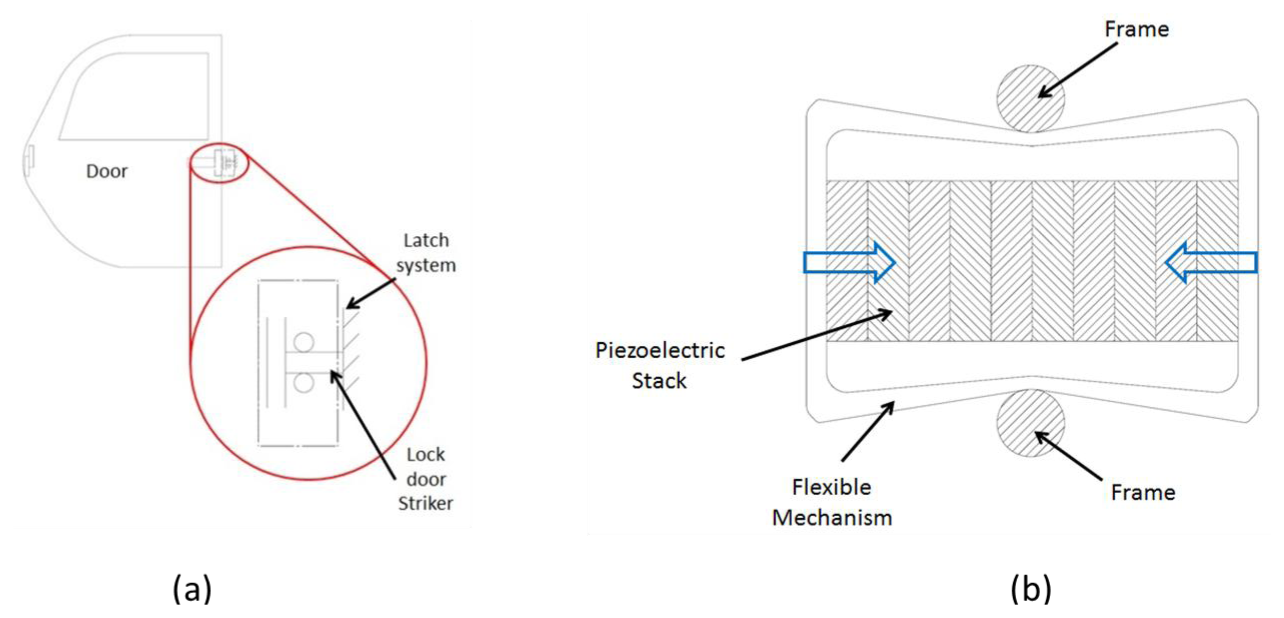
As an example, a possible application of d33 generators is represented by the car door latch system shown in Figure 11a. This assembly shows a cyclic displacement (highest value ∼1 mm) with frequency range between 0 and 10 Hz. In this view, it is possible to design an electromechanical d33 system with a metal frame, to be coupled with the internal part of the closure, able to scale the displacement in values compatible with piezostacks (Figure 11b).
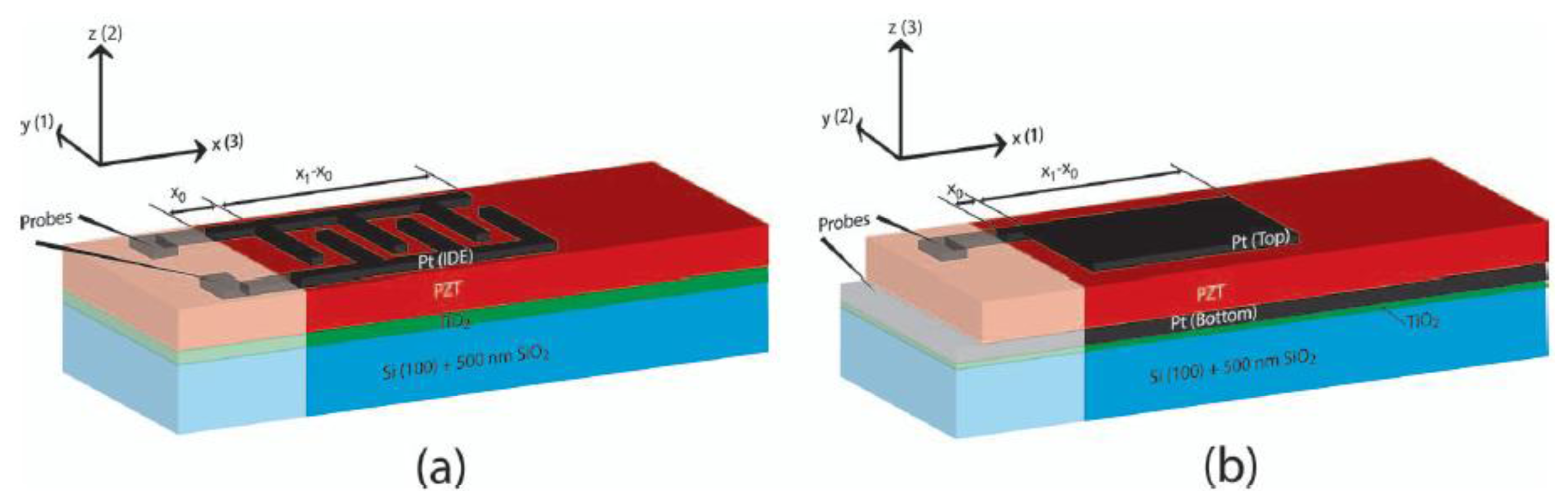
Several d33 operating modes were implemented with vibrating harvesters by using an interdigitated electrode patterning (IDE) instead of the top and bottom electrode (TBE) or parallel plate electrode (PPE) configurations of the d31 devices (Figure 12). In this way the d33 mode is obtained by letting the direction-3 to coincide to the length direction of the beam (Figure 13).
Typically a d33 mode harvester develops a greater output voltage than d31 devices because of its greater voltage coefficient (g33 > g31), and large gap between the electrodes. In d33 generators the limiting factor is the length of the piezoelectric material instead of its thickness, hence the gap between electrodes can be made larger than that of d31 devices. However, it is important to notice that greater electrode spacing requires higher voltage in order to polarize the piezoelectric material.
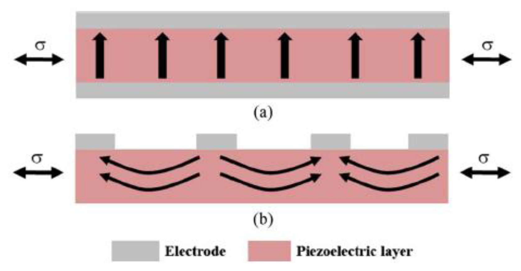
Furthermore, as it can be seen from Figure 13, the interdigitated configuration does not permit the efficient polarization of the material, resulting in curved polarization arrows. Therefore, non-polarization occurs along direction-3, whereas polarization follows in direction-1 just below the electrodes. This type of inefficiency leads to poor performance, in terms of output power.
Several research papers were published, attempting to analyze and unravel the problem of inefficient polarization [58–60]. In particular, Knight and colleagues [60] came up with finite element analysis resulting in a 0.8 optimal ratio between the width of each electrode fingers and the thickness of piezoelectric material, while the ratio between width of the cantilever beam and the finger spacing should be as large as possible. d33 and d31 unimorph configurations were also compared in terms of charge generated, by introducing a parameter that accounts for the percentage of the 3-direction polarized material (%d33). They concluded that, since d33 coefficient is roughly two times d31, (%d33 should be at least 50%, otherwise the IDE configuration has lower efficiency than the TBE one.
To date several IDE devices have been presented [57,61–66]. Jeon and colleagues developed an IDE micropower generator [61,62]. It employed an interdigitated Ti/Pt electrode patterned on top of PZT, its dimensions were submillimetric and it was able to harvest about 1μW power (2.4 Vdc after a rectifying stage) at a resonance frequency of 13.9 kHz. Furthermore, a new topology of serpentine cantilever [62] was proposed in order to increase the length of the device maintaining a limited size, but no prototypes were fabricated.
In 2010, Park and colleagues [63] fabricated and compared two millimetric piezoelectric harvesters involving d33 and a d31 modes, with same dimensions and resonant frequency. Later, the same group compared two submillimetric d33 and a d31 harvesters [57,64], after an experimental optimization of the d33 device by fabricating a set of twelve different versions of the d33 cantilever with different finger width and finger spacing. In both works higher output power was obtained with the d31 harvester and higher output voltage with the d33 device [57,63,64].
An innovative energy harvester was presented by Zhou and colleagues based on self-biased magneto-electric response [67,68], combining magnetic and piezoelectric vibrational energy harvesting. The device consists of a piezoelectric Macro-Fiber Composite (MFC, M-4010-P1, Smart Material Corp., Sarasota, FL, USA) bonded onto a magnetostrictive Ni cantilever. This device has three different operating modes (see Figure 1 for classification), mechanical electromagnetic, piezoelectric and hybrid respectively. In pure piezoelectric mode, the device harvests 168 μW on a 4 MΩ load, for a mechanical vibration of 0.17 g at 22.5 Hz frequency.
Delnavaz and Voix [69] studied the possibility of harvesting energy from ear canal dynamic motion and designed two micro-power generators, one of which is piezoelectric based. It consists of a flexible sheet of PVDF (provided by Measurement Specialties, [70]), so that the device is biocompatible [69,71]. The device is fabricated by cutting a T-shape from the piezo sheet, joining the tips of the T cross and letting the stem of the T as a tail, thus forming a ring-like device. This structure is mounted in a headset and has to be placed inside the ear canal. During mouth movements the piezo-ring will be deformed, therefore generating an electrical output.
In 2010, Qi and colleagues [72] proposed an innovative method to integrate a high efficiency piezoelectric material onto flexible materials. The method consists of printing PZT ribbons with a thickness of few hundreds nanometers, onto a PDMS substrate. It allowed achieving high piezoelectric coefficients with the advantage of flexibility. The same group also presented a flexible and stretchable device from buckled PZT ribbons, showing the possibility to integrate the high performance d33 PZT with a stretchable device [73].
More recently, Dagdeviren and colleagues [16] employed PZT ribbons in a system able to scavenge energy from movements of heart, lung and diaphragm. The harvester was arranged onto a flexible membrane, which integrates also a rechargeable battery and a bridge rectifier. The whole system was encapsulated with biocompatible layers (polyimide) and the absence of toxicity was examined with rat smooth muscle cells. The system power generation capability was in vivo tested on bovine and ovine hearts. Results showed that a stack of five PZT sheets was able to harvest up to 1.2 μW/cm2, sufficient to operate a cardiac pacemaker. Such a system can avoid risks of surgical procedures to replace the depleted batteries of implantable devices, as pacemaker, neural stimulators, cardioverter defribillators and so on.
4.3. d15 Mode Generators
d15 operating mode characterizes shear stress harvesters. In this mode the piezoelectric material is polarized along direction 1 and is subjected to a shear stress σ31. The electrical output is perpendicular to both the polarization and the applied stress. The main problem of these devices is related to the perpendicularity of the polarization direction and the electrical output (Figure 14), which constrains to use a set of electrodes for the polarization and a different set of electrodes for operation.
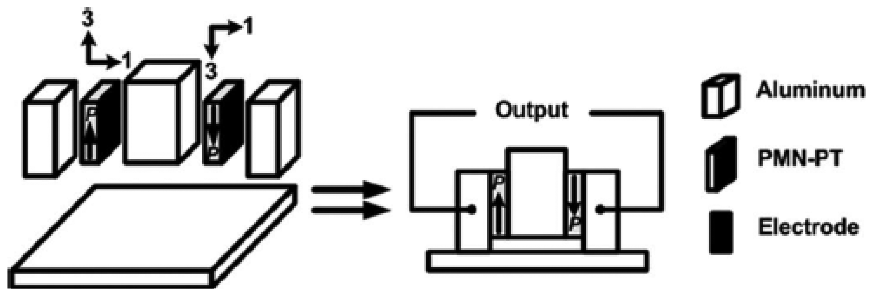
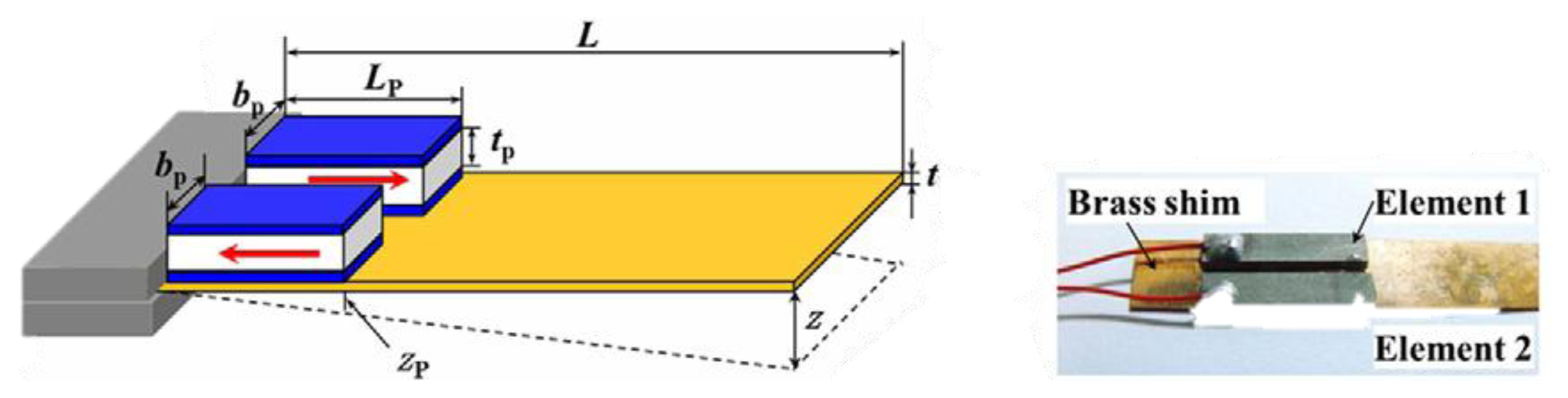
Ren and colleagues [74] proposed a non-resonant shear stress harvester involving PMN-PT crystal (last row of Table 1). It comprises two piezoelectric wafers polarized along their length, sandwiched between three aluminum blocks. One block is left free to vibrate with external oscillations (Figure 15). The two piezoelectric wafers were connected in series, with different mass load bonded to the central aluminum block. Under a brass load mass of 200 g and a corresponding acceleration of 121.6 m/s2 at 500 Hz frequency, the device delivered 11.3 V and 0.7 mW on a resistive load of 91 kΩ.
Majidi and colleagues [75] designed a shear-mode ZnO harvester that does not need a nanostructured cathode and allows a permanent bonding of electrodes to the ribbons (Figure 16). The nanoribbons are polarized along their thickness, so that a sliding movement of the electrodes induces voltage drop along the length of nanoribbons. The model developed by the authors predicted that such a system could harvest up to 100 nW/mm3.
Wang and Liu [76] developed a piezoelectric energy harvester for pressurized water flow. They employed a PZT-5H in d15 mode onto a nickel flexible diaphragm that vibrates when the pressure of flow changes. Their device achieved 0.45 nW on a matched load of 1.6 MΩ for a pressure amplitude of 20.8 kPa at 45 Hz frequency.
Zhao and colleagues [77] fabricated a piezoelectric harvester with two d15 PZT-51 connected in series, as shown in Figure 17. They also compared its performances with those of a d15 single element and demonstrated the higher performances with the series topology.
4.4. Comparison among Modes
Resonant piezoelectric generators are the easiest solution for motion harvesting [21]. They can be shaped in simple geometrical configurations by involving a d31 piezoelectric element. However, different sophisticated solutions were developed in order to increase the extracted power (d15 devices) or output voltage (d33 devices) and to scale the technology [35,50,75].
Table 2 summarizes the reviewed literature, by collectively comparing significant parameters for each device to evaluate the power factor, that is defined as the output power normalized with respect to the device volume and input acceleration (g).
Based on the analysis of various configurations in the reviewed literature, we can point out that d31 represents the most used operating mode for piezoelectric-based devices. d33 vibratory scavengers were fabricated in the attempt to overcome d31 constraints with power performance. Despite the expectations d33 devices do not show effective performances, because of polarization issues (Figure 13) due to a percentage of piezoelectric material that does not contribute to energy transduction. However, design optimizations were proposed through finite element simulations [60], but to our knowledge no device was fabricated following such guidelines. As reported in Table 2, d33 harvesters offer higher voltage output in comparison to d31 devices. On the other hand, d15 mode appears to show the best power performances but it requires a complex fabrication process.
From the perspective of employed materials, PZT has been widely used. However, PMN-PT shows higher piezoelectric coefficients with respect to PZT, while ZnO is allowing a rapid growth in nano-scale harvesting technologies. Furthermore, recent studies report high power densities (2.7 mWcm−3 in [79]) for ZnO nanowire arrays, that are being used for novel applications such as the detection of facial wrinkling with help of ZnO nanowire-based super-flexible nanogenerator harvesters [80].
5. Optimal Shapes
Rectangular cantilever beams often suffer with over strain at grounded point (near clamping) of the oscillator. Therefore, alternative mechanical structures were investigated in order to prevent overstrain [7,47,81,82]. This goal was achieved by fabricating new possible shapes for cantilever beams, such as trapezoidal beam (Figure 18). These beams distribute the strain more evenly along the structure; they also allow loading the device with higher excitation, leading to duplicate the harvested energy density. Mateu and Moll [7] investigated triangular shaped cantilevers.
Marzencki and colleagues [78,83] developed a MEMS cantilever within the European VIBration Energy Scavenging (VIBES) project, using a deep reactive ion etching on a SOI wafer. They studied the possibility of introducing two angles of curvature at the beginning and at the end of the beam (before the mass) in order to reduce the overstrain [78,83].
6. Frequency Tuning
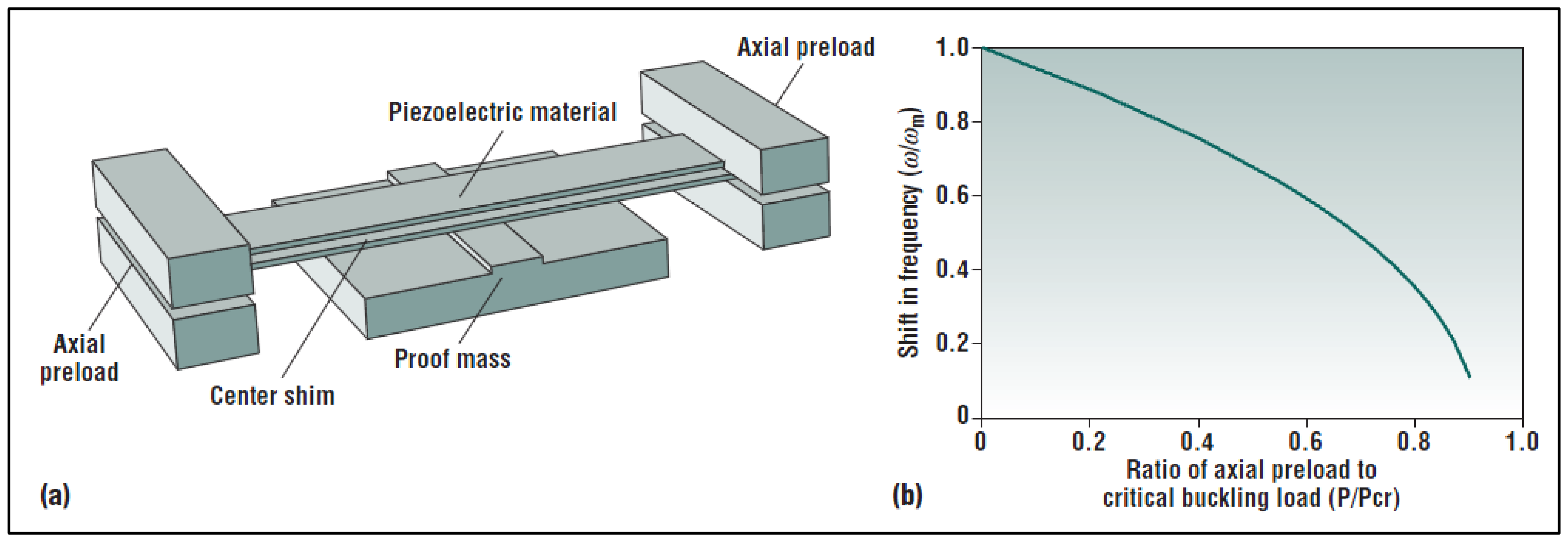
Resonant devices have limitations, as described above, because of their narrow bandwidth (approximately equal to 2ζωn, [47], which typically means few hertz), so they can work efficiently only at their natural frequency (defined by geometry and materials). In this view, several solutions were explored in order to enlarge the bandwidth of the transducer [47,84–86]. Indeed this kind of systems can be used in many applications in which frequency range is wide, due to the environmental conditions. For example in the machinery field, structures are subjected to random, broad spectrum oscillations depending on their specific working principle but also on the wear of the surfaces cyclically in contact. Some passive tuning solutions, such as a moveable clamp that changes the beam length, or nonlinear, bistable structures with destabilizing axial loads are shown in Figure 19.
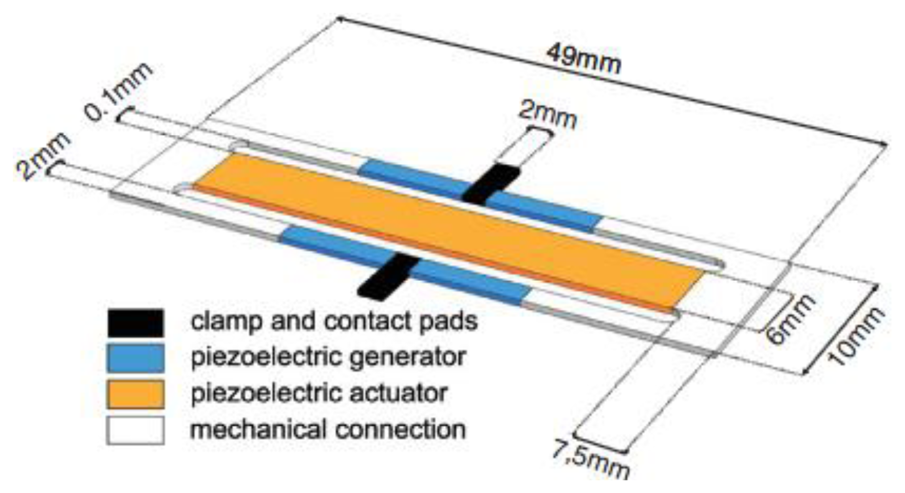
Active tuning harvesters were discussed in [87–91]. Eichhorn and colleagues [88] developed an actuated harvester using PZT both for harvesting and actuation. It consists of a two beams device with three arms (Figure 20).
In such a device, the central and larger arm houses the actuator, whilst two harvesters are located in the lateral tight arms. The actuator was designed longer than the transducers, based on previous experimental findings [92]. The control unit mainly consists of a microcontroller, an acceleration sensor and a step-up converter for actuator voltage conditioning. The control unit is equipped with a look-up table in order to avoid a higher power dissipation due to a continued use of the embedded accelerometer. The accelerometer is OFF for most of the time and is turned ON periodically to give a feedback and in case update the look-up table (to overcome aging effects and temperature dependence). The authors reported that this device is capable to harvest up to 90 μW at an acceleration amplitude of 0.6 g. The natural frequency can be tuned within 150 and 215 Hz with actuator voltages between −30 and +45 V. Furthermore, the average consumption of the whole control unit is around 11 μW if the system maintains a constant resonance frequency, however the power consumption can increase by several orders of magnitude if the ambient vibration shifts. Furthermore, it is important to note that the equipped dc-dc converter does not allow negative voltages, so the authors are working on an enhanced device with separated ground electrodes in order to overcome this issue.
Another approach is to enlarge the bandwidth by fabricating an array of cantilevers with different natural frequencies [43,93]. Such device allows to convert energy from different sources at different frequencies, however it reduces the harvested power per unit area because only one cantilever of the array works efficiently for a given source (at a given frequency), while the others do not.
Roundy and colleagues proposed a similar device obtained connecting three spring-mass-damper systems with different natural frequencies [47]. The resulting device output is almost an overlap of the single subsystems response (Figure 21).
7. Non-Resonant Devices
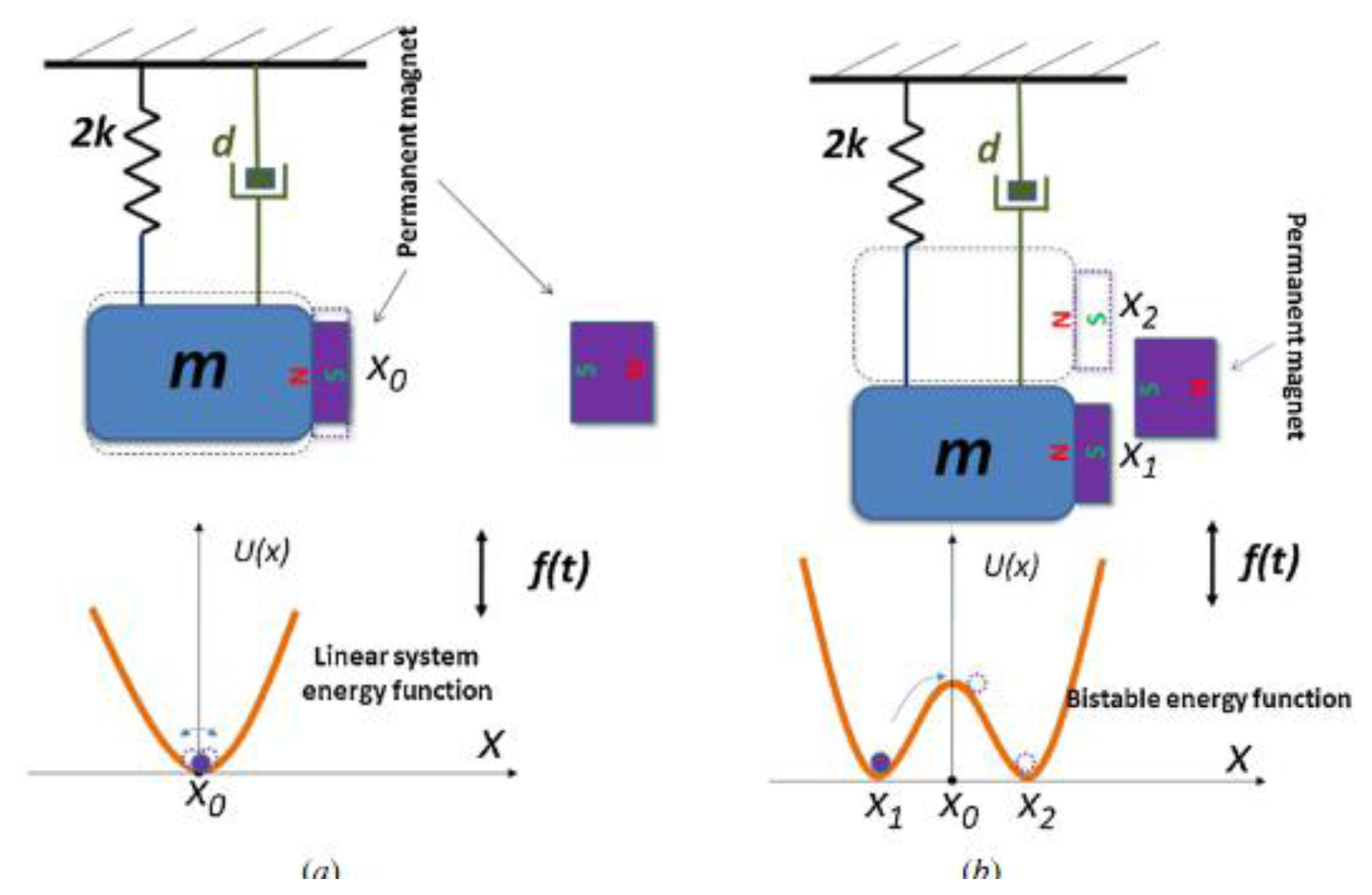
A novel approach based on nonlinear oscillators was proposed by Cottone and colleagues [94]. The authors demonstrated that a bistable oscillator could widen the bandwidth of a traditional resonant system. The design of this device derives from the inverted pendulum; in which reaction forces from two permanent magnets are used (one on the tip mass of cantilever, and the other just in front on an adjustable stage) to provide two stable states.
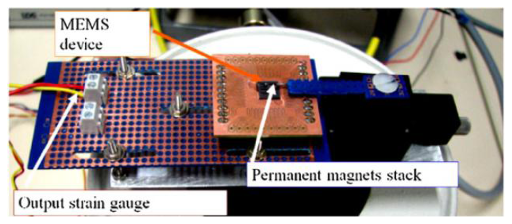
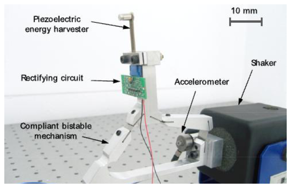
Among all the proposed devices [95–100], Andò and colleagues [96] developed a MEMS harvester based on the bistable oscillator model (Figure 22).
It can be referred to a mass-spring-damper system, similar to Equation (8), but with an additional nonlinear term described by a nonlinear potential energy function:
The potential energy function U(z) can be chosen from a variety of equations [102,103]. Here, for simplicity, we report a standard quadratic equation:
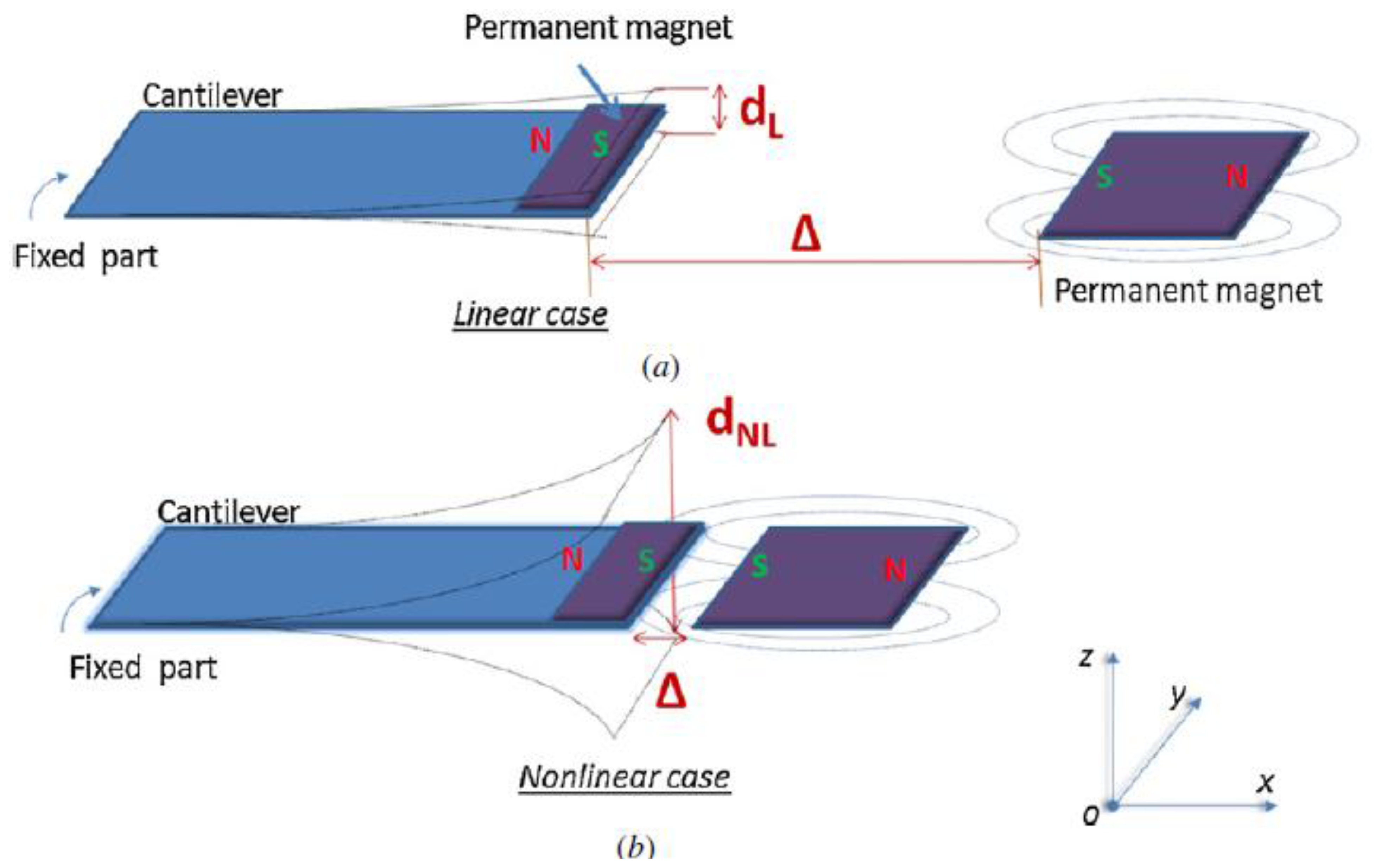
Calling Δ the distance between magnets (Figure 24), three cases can be described:
Large value of Δ: magnetic force is negligible and the cantilever behavior is linear, such as resonant devices. These refer to the model reported in Figure 23a;
Small value of Δ: the external magnet is close to the cantilever tip, which is confined in one of the two stable states along the z axis of Figure 24. The system cannot switch between the two stable states due to the high commutation potential U0. In this case, the oscillation is small and linear around one of the two stable states.
Medium value of Δ: in a particular range of Δ (depending on the vibration input) the system is able to commute between two stable states, which results in non-linear behavior of the device.
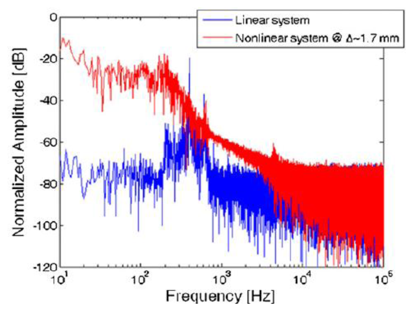
The fabricated MEMS device operated in the latter condition (nonlinear oscillation). Experimental tests resulted in the displacement spectrum (for the tip) shown in Figure 25, under an excitation input of Gaussian white noise with a standard deviation σ = 20 μN (that corresponds to an acceleration of 7.7 ms−2), and a distance Δ ∼1.7 mm between the magnets.
The bi-stable behavior was also achieved by involving two magnets with the same polarity of the cantilever magnetic tip [104,105]. These magnets are deployed not just in front of the tip, but shifted upwards and downwards within a frontal stage, to obtain an attraction between the magnetic tip and the two fixed magnets. Other research papers showed similar bistable systems where the switching between stable states is driven by internal signals [106,107].
Qiu and colleagues [108] demonstrated a bi-stable device consisting of a clamped-clamped buckled beam. Xu and colleagues [109] proposed a simply supported buckled beam, stating that this mechanism enhances the clamped-clamped transduction mechanism. Other bistable solutions based on buckled beam configuration were demonstrated by Arrieta and colleagues in [110] and by Cottone and colleagues in [111]. Buckled beams do not require permanent magnets and are therefore better suited for miniaturization. Andò and colleagues investigated new solutions to design bistable vibration harvesters in [112,113].
A bio-inspired device was proposed as well [114] (Figures 26 and 27). It is designed to mimic the auditory hair bundle structure. The auditory structure is responsible to stimulate the brain with electrical signals in response to the oscillations due to pressure forces of propagated sound. It mechanically amplifies the movements of the hair cells, thanks to a negative stiffness, which conveys a bi-stable behavior. The proposed device is composed by a four bar structure, linked by thin spring steel flexural joints. A piezoelectric cantilever can be placed on the coupler link.
Real harvesting applications are characterized by wide spectrum vibrations [115], with predominance of low frequencies in the case of wearable body harvesters. Non-resonant solutions allow enlarging devices bandwidth and therefore obtain effective harvesting performances, without augmenting devices area or adding power demanding self-tuning features. Moreover, bistable systems show a low-pass behavior that allows harvesting low frequency vibrations without the need for large masses and devices (necessary in resonant cantilevers). Table 3 summarizes the reviewed non-resonant devices and compares their main characteristics.
8. Rotational Devices
Although the piezoelectric effect is inherently related to axial elongations, several device configurations were proposed as rotatory harvesters [85,116–125], mainly by transforming a rotatory excitation into a longitudinal strain. Among these, Gu and Livermore [85] presented a compact self-tuning rotatory harvester, consisting in a rigid piezoelectric beam and a flexible beam with a tip mass at its end (a steel ball). During operation, the steel ball impacts the generating beam, letting it to vibrate. The system natural frequency is determined by the flexible beam natural frequency, which varies with the imposed centrifugal force.
Khameneifar and colleagues [119,120] applied the piezoelectric cantilever concept to a rotating shaft, as shown in Figure 28. This approach allows employing a piezoelectric device for monitoring rotating machines such as turbines or tires. The device (employing a single PZT element with a single 5 cm length cantilever beam and a 105 g tip mass) driven at 138 rad/s was able to harvest 6.4 mW on an optimum load resistance of 40 kΩ, with a corresponding output voltage of about 16 V.
Pillatsch and colleagues [121] developed a harvester composed of a fixed piezoelectric beam and an eccentric proof mass free to rotate, similar to the Seiko Kinetik watch. This device was designed for human body applications, and was tested on an upper limb during a running task. It was able to harvest up to 43 μW at 2 Hz and 20 ms−2.
Karami and colleagues [122] proposed two configurations of wind turbine, both consisting of a circular array of cantilever beams clamped below a windmill. These beams vibrate in response to the movement of the windmill, which is equipped with repulsive magnets.
9. Conditioning Circuitry
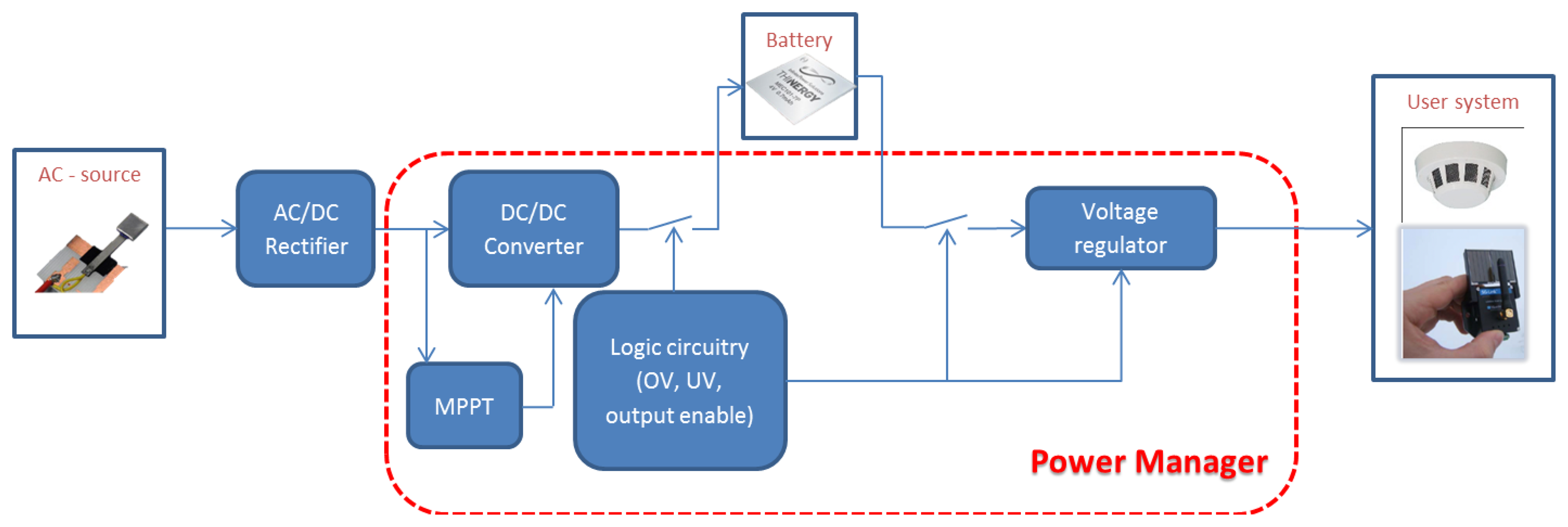
The scientific and technological challenges of energy harvesting systems also deal with power managers. These devices are responsible for transferring harvested energy from generator to a host device and in most cases to a storage element as well. A typical schematic diagram of a power manager is shown in Figure 29.
Power managers are designed both for DC and AC sources. They typically employ a DC-DC converter, mainly for impedance matching and also to match the source voltage with the battery charging level. In case of alternate sources, a rectifier is required. In case of direct current sources, impedance matching can be achieved through the use of a maximum power point tracker (MPPT). It implements algorithms apt to follow the input power peaks, which is equivalent to fix the generator operating point by acting on the equivalent impedance of the downstream circuitry. Although MPPT units are suited almost uniquely for DC sources, Yi and colleagues [126] discussed a strategy to implement an energy adaptive algorithm for vibration harvesters. The logic circuitry is designated to control and manage the charge and discharge phases of the battery. Overvoltage and undervoltage boundaries can be controlled with the help of comparators and switches. Voltage thresholds are often configurable by users using resistive dividers. Piezoelectric generators are AC sources, hence their output has to be rectified and regulated to supply host devices. The simplest rectifier can be a diode bridge rectifier (Figure 30). The AC-DC converter can be followed by a DC-DC converter, for power optimization and voltage regulation [127,128].
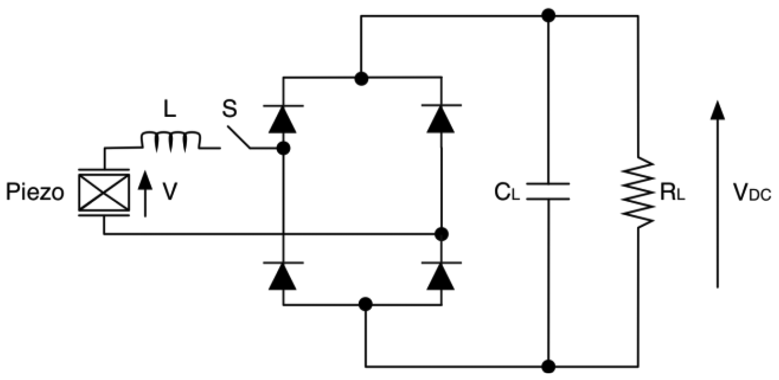
Another possible circuital interface is the parallel-SSHI (synchronized switch harvesting on inductor) [129–131]. This approach allows to enhance the coupling coefficient of the electromechanical system using piezomaterials [130,132–134], it allows to gain up to 10 times in terms of harvested energy [135]. The technique was derived from a semi-passive technique developed for mechanical structures, called SSD (synchronized switch damping) [136–140]. Such configuration adds an inductor-switch branch in parallel to the source (Figure 31).
When the device displacement is maximum, the switch is turned ON. In this condition the internal capacitance and the inductor constitute an oscillator, where the characteristic electrical period must be chosen much smaller than the mechanical vibration period. The circuit allows to invert quasi-instantaneously the voltage of the piezoelectric element and thus to put in phase the vibration velocity and the generated voltage [141–143].
A possible implementation of the parallel-SSHI interface consists of two switches, one for the positive half-wave and another one for the negative. The switches are implemented through two MOS transistors driven by the output of a comparator that reads the derivative of the piezoelectric voltage, in order to catch the peak and let the inductor to discharge the parasitic capacitance [131].
This technique allows to dramatically increase the voltage output or to obtain the same output of a standard interface device while reducing the volume of the piezoelectric element.
Based on the same concept, a series-SSHI rectifier consists of an inductor-switch branch added in series to the piezoelectric element, followed by a diode bridge rectifier (Figure 32). The switch control is the same as described above for parallel-SSHI.
Lefeuvre and colleagues [28] as well reported a synchronous charge extraction interface (Figure 33). The extraction is triggered by the maxima and minima of the displacement u. When the switch is closed, the electrical energy of the internal capacitor is transferred to the inductor, and when the switch is re-opened the energy stored in the inductor is transferred to the downstream smoothing capacitor.
An experimental comparison between these configurations for a constant force amplitude input was presented in [28]. The four techniques have the same maximum harvested power, but at different values of the electromechanical coupling factor. Practically, the synchronous charge extraction technique reaches the maximum at lower electromechanical coupling factors, enabling reduction in required amount of piezoelectric materials, since k2 is roughly proportional to the amount of material. Moreover, synchronous charge extraction is indifferent to impedance matching.
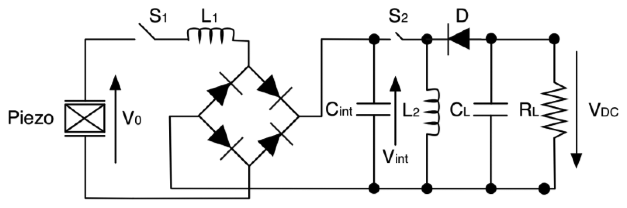
Lallart and colleagues [144] developed double synchronized switch harvesting (DSSH) by adding a buck-boost converter to the above described original idea of parallel-SSHI. This one is not driven in a conventional way. Referring to Figure 34, S2 is closed only when Cint is fully charged by the diode bridge rectifier (after every cycle), while S1 is ON when energy on L2 is maximum.
Several other switching techniques were reported by Guyomar and colleagues [142]. All these strategies, however, rely on a deterministic knowledge of the source frequency. If this frequency is time variant or random, the above discussed systems fail.
Giusa and colleagues [145] recently demonstrated a novel approach (called Random mechanical switching harvesting on inductor—RMSHI), which does not require deterministic synchronization. It employs a mechanical switch consisting of two mechanical stoppers. These close the circuit when the beam reaches maximum deflection. Furthermore, the mechanical switch prevents from extra voltage across the inductor, which would occur using an electronic switch.
Commercial solutions are also made available as a result of the research progresses achieved in the last years. Linear Technology (Milpitas, CA, USA) has come up with a series of conditioning devices for energy harvesting. Those circuits are targeted for piezoelectric-based harvesters [146–148] and equipped with low-loss full-wave bridge rectifier followed by a buck or a buck-boost converter. They are also provided with embedded LDOs enabling selectable output voltages, which may also be used to charge batteries.
10. Conclusions
Though piezoelectric energy harvesting has been thoroughly investigated since the late 1990s [149], it still remains an emerging technology and critical area of interest. Energy harvesting application fields so far mainly focused on low power devices due to their limited transduction efficiencies [150].
To date, researchers are following distinct ways in developing piezoelectric energy harvesting technology. New materials, configuration approaches and operating modes are under study, and some of these valuable solutions were proposed in order to achieve large bandwidth harvesters that are able to scavenge energy from diverse environments.
Resonant d33 cantilever beams need optimization, but several interesting solutions and approaches that were published can push forward the research. d15 harvesters are still too complex to be fabricated, but exhibit great potential.
In this review paper these configurations have been briefly studied using a comparison table with respect to d31, reporting various factors. From this analysis we can conclude that d15 is more efficient than other modes, d33 has higher output voltages, simplifying the power conversion process, whereas d31 is the simplest solution found in terms of fabrication process and performances (in most cases).
Considering nanoscale harvesters, they represent a promising but still emerging technique that requires to be consolidated. Non-resonant solutions, as well as frequency tuning methods, are powerful instruments to push forward the growth of vibration harvesting techniques. However, though several non-resonant solutions were demonstrated, new roads can be explored. As an example, in electromagnetic vibration harvesting a well-known technique to achieve bistability involves mechanical bumpers [151,152]. Furthermore, all these piezoelectric harvesting research branches could be merged. Likely, a bistable harvester involving a high efficiency d15 material, equipped with a proper conditioning circuitry, would achieve significant results.
The limit in terms of harvested energy density has still to be overcome. This has been the main technological challenge so far. A well-integrated roadmap was designed in the framework of the Guardian Angels Coordination Action within the Future and Emerging Technologies Flagship initiative funded by the European Commission [153]. In this framework, research efforts are focusing on the transducer and also on the integration with the downstream conditioning circuitry, power management circuits and application devices.
Acknowledgments
This work was supported in part by the NanoBioTouch European project (Nano-resolved multi-scale investigations of human tactile sensations and tissue engineered nanobiosensors; EU-FP7-NMP-228844), by the PRIN/HandBot Italian project (Biomechatronic hand prostheses endowed with bio-inspired tactile perception, bi-directional neural interfaces and distributed sensori-motor control; CUP: B81J12002680008; prot.: 20102YF2RY) by the SensAlone Working Capital Grant awarded by Telecom Italia (Self-powered Stand-Alone Sensing System), and by Scuola Superiore Sant'Anna.
The authors would like to thank Francesca Spagnuolo for support in getting permissions to reproduce some of the figures integrated in the manuscript.
Author Contributions
This paper has been written thanks to the intensive work of each author. Renato Caliò was the main responsible of the bibliographic search and analysis and Calogero Maria Oddo was the scientific coordinator of the study. Renato Caliò and Calogero Maria Oddo wrote the paper and worked on each section of the present manuscript. Udaya Bhaskar Rongala gave important contributions in Sections 2 and 4.1. Domenico Camboni wrote several parts along Section 4, while Mario Milazzo and Cesare Stefanini contributed mainly in Sections 4.2 and 6. Gianluca de Petris contributed mainly to the discussion of application scenarios in Sections 1 and 10. All the authors helped in reviewing and deeply analyzing the manuscript until its final version.
Conflicts of Interest
The authors declare no conflicts of interest.
References
- Torah, R.; Glynne-Jones, P.; Tudor, M.; O'Donnell, T.; Roy, S.; Beeby, S. Self-powered autonomous wireless sensor node using vibration energy harvesting. Meas. Sci. Technol. 2008, 19, 125202. [Google Scholar]
- Magno, M.; Boyle, D.; Brunelli, D.; O'Flynn, B.; Popovici, E.; Benini, L. Extended wireless monitoring through intelligent hybrid energy supply. IEEE Trans. Ind. Electron. 2014, 61, 1871–1881. [Google Scholar]
- Anton, S.R.; Inman, D.J. Vibration energy harvesting for unmanned aerial vehicles. Proceedings of the 15th International Symposium on Smart Structures and Materials & Nondestructive Evaluation and Health Monitoring, San Diego, CA, USA, 9–13 March 2008. [CrossRef]
- Chapuis, A.; Jaquet, E.; Grandvoinet, R.S. The History of the Self-Winding Watch, 1770–1931; Éditions du Griffon: Gloucestershire, UK, 1956. [Google Scholar]
- Paradiso, J.A.; Hsiao, K.Y.; Benbasat, A.Y.; Teegarden, Z. Design and implementation of expressive footwear. IBM Syst. J. 2000, 39, 511–529. [Google Scholar]
- Mateu, L.; Fonellosa, F.; Moll, F. Electrical characterization of a piezoelectric film-based power generator for autonomous werable devices. Proceedings of the XVIII Conference on Design of Circuits and Integrated Systems, Ciudad Real, Spain, November 2003; Volume 18.
- Mateu, L.; Moll, F. Optimum piezoelectric bending beam structures for energy harvesting using shoe inserts. J. Intell. Mater. Syst. Struct. 2005, 16, 835–845. [Google Scholar]
- Paradiso, J.A.; Starner, T. Energy scavenging for mobile and wireless electronics. IEEE Pervas. Comput. 2005, 4, 18–27. [Google Scholar]
- Lucarotti, C.; Oddo, C.M.; Vitiello, N.; Carrozza, M.C. Synthetic and bio-artificial tactile sensing: A review. Sensors 2013, 13, 1435–1466. [Google Scholar]
- Jornet, J.M.; Akyildiz, I.F. Joint energy harvesting and communication analysis for perpetual wireless nanosensor networks in the terahertz band. IEEE Trans. Nanotechnol. 2012, 11, 570–580. [Google Scholar]
- Allameh, S.M.; Akogwu, O.; Collinson, M.; Thomas, J.; Soboyejo, W.O. Piezoelectric generators for biomedical and dental applications: Effects of cyclic loading. J. Mater. Sci. 2007, 18, 39–45. [Google Scholar]
- Yang, Y.; Zhang, H.; Lin, Z.-H.; Zhou, Y.S.; Jing, Q.; Su, Y.; Yang, J.; Chen, J.; Hu, C.; Wang, Z.L. Human skin based triboelectric nanogenerators for harvesting biomechanical energy and as self-powered active tactile sensor system. ACS Nano 2013, 7, 9213–9222. [Google Scholar]
- Hosoda, K.; Tada, Y.; Asada, M. Anthropomorphic robotic soft fingertip with randomly distributed receptors. Robot. Auton. Syst. 2006, 54, 104–109. [Google Scholar]
- Oddo, C.M.; Controzzi, M.; Beccai, L.; Cipriani, C.; Carrozza, M.C. Roughness encoding for discrimination of surfaces in artificial active-touch. IEEE Trans. Robot. 2011, 27, 522–533. [Google Scholar]
- Tanner, K. Titanium in medicine. J. Eng. Med. Inst. Mech. Eng. Proc. 2001, 216, 215. [Google Scholar]
- Dagdeviren, C.; Yang, B.D.; Su, Y.; Tran, P.L.; Joe, P.; Anderson, E.; Xia, J.; Doraiswamy, V.; Dehdashti, B.; Feng, X.; et al. Conformal piezoelectric energy harvesting and storage from motions of the heart, lung, and diaphragm. Proc. Natl. Acad. Sci. USA 2014, 111, 1927–1932. [Google Scholar]
- Starner, T. Human-powered wearable computing. IBM Syst. J. 1996, 35, 618–629. [Google Scholar]
- Worthington, E.L. Techniques, Piezoelectric Energy Harvesting: Enhancing Power Output by Device Optimization and Circuit; Cranfield University: Bedford, UK, 2010. [Google Scholar]
- Mhetre, M.R.; Nagdeo, N.S.; Abhyankar, H.K. Micro energy harvesting for biomedical applications: A review. Proceedings of the IEEE 2011 3rd International Conference on Electronics Computer Technology (ICECT), Kanyakumari, India, 8–10 April 2011; Volume 3, pp. 1–5.
- Roundy, S.; Wright, P.K.; Rabaey, J. A study of low level vibrations as a power source for wireless sensor nodes. Comput. Commun. 2003, 26, 1131–1144. [Google Scholar]
- Beeby, S.P.; Tudor, M.J.; White, N. Energy harvesting vibration sources for microsystems applications. Meas. Sci. Technol. 2006, 17, R175–R195. [Google Scholar]
- Wikipedia: Vitruvian Man. Available online: http://en.wikipedia.org/wiki/File:Da_Vinci_Vitruve_Luc_Viatour.jpg (accessed on 28 February 2014).
- Fukada, E.; Yasuda, I. On the piezoelectric effect of bone. J. Phys. Soc. Jpn. 1957, 12, 1158–1162. [Google Scholar]
- Jaffe, B. Piezoelectric Ceramics (Vol. 3); Academic Press: London, UK, 1971. [Google Scholar]
- The Piezoelectric Effect. Available online: http://www.aurelienr.com/electronique/piezo/piezo.pdf (accessed on 28 February 2014).
- 176–1987— IEEE Standard on Piezoelectricity. Available online: http://ieeexplore.ieee.org/xpl/login.jsp?tp=&arnumber=26560&url=http%3A%2F%2Fieeexplore.ieee.org%2Fxpls%2Fabs_all.jsp%3Farnumber%3D26560 (accessed on 28 February 2014).
- Richards, C.D.; Anderson, M.J.; Bahr, D.F.; Richards, R.F. Efficiency of energy conversion for devices containing a piezoelectric component. J. Micromech. Microeng. 2004, 14, 717–721. [Google Scholar]
- Lefeuvre, E.; Badel, A.; Richard, C.; Petit, L.; Guyomar, D. A comparison between several vibration-powered piezoelectric generators for standalone systems. Sens. Actuators A Phys. 2006, 126, 405–416. [Google Scholar]
- Priya, S.; Inman, D.J. Energy Harvesting Technologies; Springer: Berlin, Germany, 2009. [Google Scholar]
- Baldisserri, C.; Gardini, D.; Galassi, C. Sharp silicon/lead zirconate titanate interfaces by electrophoretic deposition on bare silicon wafers and post-deposition sintering. Sens. Actuators A Phys. 2012, 174, 123–132. [Google Scholar]
- Koka, A.; Zhou, Z.; Sodano, H.A. Vertically aligned batio3 nanowire arrays for energy harvesting. Energy Environ. Sci. 2014, 7, 288–296. [Google Scholar]
- Anton, S.R.; Sodano, H.A. A review of power harvesting using piezoelectric materials (2003–2006). Smart Mater. Struct. 2007, 16, R1. [Google Scholar]
- Shen, D.; Choe, S.Y.; Kim, D.J. Analysis of piezoelectric materials for energy harvesting devices under high-g vibrations. Jpn. J. Appl. Phys. 2007, 46, 6755–6760. [Google Scholar]
- Kranz, B.; Benjeddou, A.; Drossel, W.G. Numerical and experimental characterizations of longitudinally polarized piezoelectric d15 shear macro-fiber composites. Acta Mech. 2013, 224, 1–17. [Google Scholar]
- Wang, Z.L.; Song, J. Piezoelectric nanogenerators based on zinc oxide nanowire arrays. Science 2006, 312, 242–246. [Google Scholar]
- Wang, Z.L.; Song, J. Supporting Online Material for Piezoelectric Nanogenerators Based on Zinc Oxide Nanowire Arrays. Available online: http://www.sciencemag.org/content/suppl/2006/04/13/312.5771.242.DC1/WangZ.SOM.pdf (accessed on 28 February 2014).
- Morgan-Electro-Ceramics Tp-226 Properties of Piezoelectricity Ceramics. Available online: http://traktoria.org/files/sonar/piezoceramics/morgan/properties_of_piezoelectric_ceramics_%28pzt-4_pzt-5a_pzt-5h_pzt-8%29.pdf (accessed on 28 February 2014).
- Ferroperm-Piezoceramics Ferroperm Data Matrix. Available online: http://www.ferroperm-piezo.com/ (accessed on 28 February 2014).
- Channel-Industries-Inc. Piezoelectric Ceramics. Available online: http://www.channelindustries.com/_includes/chan_cat.pdf (accessed on 28 February 2014).
- Peng, J.; Luo, H.S.; Lin, D.; Xu, H.Q.; He, T.H.; Jin, W.Q. Orientation dependence of transverse piezoelectric properties of 0.70Pb(Mg1/3Nb2/3)O3-0.30PbTiO3 single crystals. Appl. Phys. Lett. 2004, 85, 6221–6223. [Google Scholar]
- Zhang, S.; Li, F.; Sherlock, N.P.; Luo, J.; Lee, H.J.; Xia, R.; Meyer, R.J., Jr.; Hackenberger, W.; Shrout, T.R. Recent developments on high Curie temperature PIN-PMN-PT ferroelectric crystals. J. Cryst. Growth 2011, 318, 846–850. [Google Scholar]
- Peng, J.; Chen, J.; Luo, H.; He, T.; Xu, H.; Lin, D. Shear-mode piezoelectric properties of 0.69Pb(Mg1/3Nb2/3)O3-0.31PbTiO3 single crystals. Solid State Commun. 2004, 130, 53–57. [Google Scholar]
- Ferrari, M.; Ferrari, V.; Guizzetti, M.; Marioli, D.; Taroni, A. Piezoelectric multifrequency energy converter for power harvesting in autonomous microsystems. Sens. Actuators A Phys. 2008, 142, 329–335. [Google Scholar]
- Erturk, A.; Inman, D.J. Issues in mathematical modeling of piezoelectric energy harvesters. Smart Mater. Struct. 2008, 17, 065016. [Google Scholar]
- Williams, C.; Yates, R.B. Analysis of a micro-electric generator for microsystems. Sens. Actuators A Phys. 1996, 52, 8–11. [Google Scholar]
- Gafforelli, G. Energy Harvesting: State of Art. Available online: ftp://ftp.stru.polimi.it/incoming/gafforelli/Energy%20Harvesting/Pres_EH-State%20of%20art.pdf (accessed on 28 February 2014).
- Roundy, S.; Leland, E.S.; Baker, J.; Carleton, E.; Reilly, E.; Lai, E.; Otis, B.; Rabaey, J.M.; Wright, P.K.; Sundararajan, V. Improving power output for vibration-based energy scavengers. IEEE Pervas. Comput. 2005, 4, 28–36. [Google Scholar]
- Ng, T.H. Sensitivity analysis and energy harvesting for a self-powered piezoelectric sensor. J. Intell. Mater. Syst. Struct. 2005, 16, 785–797. [Google Scholar]
- Lu, F.; Lee, H.P.; Lim, S.P. Modeling and analysis of micro piezoelectric power generators for micro-electromechanical-systems applications. Smart Mater. Struct. 2004, 13, 57–63. [Google Scholar]
- Yang, R.; Qin, Y.; Dai, L.; Wang, Z.L. Power generation with laterally packaged piezoelectric fine wires. Nat. Nano 2009, 4, 34–39. [Google Scholar]
- Umeda, M.; Nakamura, K.; Ueha, S. Analysis of the transformation of mechanical impact energy to electric energy using piezoelectric vibrator. Jpn. J. Appl. Phys. 1996, 35, 3267–3273. [Google Scholar]
- Umeda, M.; Nakamura, K.; Ueha, S. Energy storage characteristics of a piezo-generator using impact induced vibration. Jpn. J. Appl. Phys. 1997, 36, 3146–3151. [Google Scholar]
- Xu, C.N.; Akiyama, M.; Nonaka, K.; Watanabe, T. Electrical power generation characteristics of PZT piezoelectric ceramics. IEEE Trans. Ultrason. Ferroelectr. Freq. Control 1998, 45, 1065–1070. [Google Scholar]
- Funasaka, T.; Furuhata, M.; Hashimoto, Y.; Nakamura, K. Piezoelectric generator using a LiNbO3 plate with an inverted domain. Proc. IEEE Ultrason. Symp. 1998, 1, 959–962. [Google Scholar]
- Chure, M.C.; Wu, L.; Wu, K.K.; Tung, C.C.; Lin, J.S.; Ma, W.C. Power generation characteristics of PZT piezoelectric ceramics using drop weight impact techniques: Effect of dimensional size. Ceramics Int. 2014, 40, 341–345. [Google Scholar]
- Chidambaram, N.; Mazzalai, A.; Muralt, P. Measurement of effective piezoelectric coefficients of PZT thin films for energy harvesting application with interdigitated electrodes. IEEE Trans. Ultrason. Ferroelectr. Freq. Control 2012, 59, 1624–1631. [Google Scholar]
- Kim, S.B.; Park, H.; Kim, S.H.; Wikle, H.C.; Park, J.H.; Kim, D.J. Comparison of MEMS PZT cantilevers based on d31 and d33 modes for vibration energy harvesting. J. Microelectromech. Syst. 2013, 22, 26–33. [Google Scholar]
- Bowen, C.R.; Nelson, L.J.; Stevens, R.; Cain, M.G.; Stewart, M. Optimisation of interdigitated electrodes for piezoelectric actuators and active fibre composites. J. Electroceram. 2006, 16, 263–269. [Google Scholar]
- Paradies, R.; Melnykowycz, M.M. State of stress in piezoelectric elements with interdigitated electrodes. J. Electroceram. 2010, 24, 137–144. [Google Scholar]
- Knight, R.R.; Mo, C.; Clark, W.W. MEMS interdigitated electrode pattern optimization for a unimorph piezoelectric beam. J. Electroceram. 2011, 26, 14–22. [Google Scholar]
- Jeon, Y.; Sood, R.; Jeong, J.-H.; Kim, S.-G. MEMS power generator with transverse mode thin film PZT. Sens. Actuators A Phys. 2005, 122, 16–22. [Google Scholar]
- Choi, W.; Jeon, Y.; Jeong, J.-H.; Sood, R.; Kim, S.-G. Energy harvesting MEMS device based on thin film piezoelectric cantilevers. J. Electroceram 2006, 17, 543–548. [Google Scholar]
- Park, J.H.; Ahn, H.; Kim, S.B.; Kim, S.H.; Kim, D.J. Comparison of transduction efficiency for energy harvester between piezoelectric modes. In MEMS and Nanotechnology; Volume 2, Proulx, T., Ed.; Springer: New York, NY, USA, 2010; pp. 33–39. [Google Scholar]
- Kim, S.B.; Park, J.H.; Kim, S.H.; Ahn, H.; Wikle, H.C.; Kim, D.J. Fabrication and analytical modeling of transverse mode piezoelectric energy harvesters. MRS Proc. 2011, 1397, 84–89. [Google Scholar]
- Shen, Z.; Liu, S.; Miao, J.; Woh, L.S.; Wang, Z. Proof mass effects on spiral electrode d33 mode piezoelectric diaphragm-based energy harvester. Proceedings of the IEEE International Conference on Micro Electro Mechanical Systems (MEMS), Taipei, Taiwan, 20–24 January 2013; pp. 821–824.
- Han, M.; Chan, Y.C.; Liu, W.; Zhang, S.; Zhang, H. Low frequency PVDF piezoelectric energy harvester with combined d31 and d33 operating modes. Proceedings of the IEEE NEMS 8th Annual IEEE International Conference on Nano/Micro Engineered and Molecular Systems, Suzhou, China, 7–10 April 2013; pp. 440–443.
- Zhou, Y.; Yang, S.C.; Apo, D.J.; Maurya, D.; Priya, S. Tunable self-biased magnetoelectric response in homogenous laminates. Appl. Phys. Lett. 2012, 101, 232905. [Google Scholar]
- Zhou, Y.; Apo, D.J.; Priya, S. Dual-phase self-biased magnetoelectric energy harvester. Appl. Phys. Lett. 103.
- Delnavaz, A.; Voix, J. Energy harvesting for in-ear devices using ear canal dynamic motion. IEEE Trans. Ind. Electron. 2014, 61, 583–590. [Google Scholar]
- Piezo Sensor—Metallized Film Sheets. Available online: http://www.meas-spec.com/product/t_product.aspx?id=2488 (accessed on 28 February 2014).
- Sun, C.; Shi, J.; Bayerl, D.J.; Wang, X. PVDF microbelts for harvesting energy from respiration. Energy Environ. Sci. 2011, 4, 4508–4512. [Google Scholar]
- Qi, Y.; Jafferis, N.T.; Lyons, K., Jr.; Lee, C.M.; Ahmad, H.; McAlpine, M.C. Piezoelectric ribbons printed onto rubber for flexible energy conversion. Nano Lett. 2010, 10, 524–528. [Google Scholar]
- Qi, Y.; Kim, J.; Nguyen, T.D.; Lisko, B.; Purohit, P.K.; McAlpine, M.C. Enhanced piezoelectricity and stretchability in energy harvesting devices fabricated from buckled PZT ribbons. Nano Lett. 2011, 11, 1331–1336. [Google Scholar]
- Ren, B.; Or, S.; Wang, F.; Zhao, X.; Luo, H.; Li, X.; Zhang, Q.; Di, W.; Zhang, Y. Piezoelectric energy harvesting based on shear mode 0.71Pb(Mg1/3Nb2/3)O3-0.29PbTiO3 single crystals. IEEE Trans. Ultrason. Ferroelectr. Freq. Control 2010, 57, 1419–1425. [Google Scholar]
- Majidi, C.; Haataja, M.; Srolovitz, D.J. Analysis and design principles for shear-mode piezoelectric energy harvesting with zno nanoribbons. Smart Mater. Struct. 2010, 19, 055027. [Google Scholar]
- Wang, D.A.; Liu, N.Z. A shear mode piezoelectric energy harvester based on a pressurized water flow. Sens. Actuators A Phys 2011, 167, 449–458. [Google Scholar]
- Zhao, J.; Zheng, X.; Zhou, L.; Zhang, Y.; Sun, J.; Dong, W.; Deng, S.; Peng, S. Investigation of a d15 mode PZT-51 piezoelectric energy harvester with a series connection structure. Smart Mater. Struct. 2012, 21, 105006. [Google Scholar]
- Marzencki, M.; Ammar, Y.; Basrour, S. Integrated power harvesting system including a MEMS generator and a power management circuit. Sens. Actuators A Phys. 2007, 145–146, 887–890. [Google Scholar]
- Xu, S.; Qin, Y.; Xu, C.; Wei, Y.; Yang, R.; Wang, Z.L. Self-powered nanowire devices. Nat. Nanotechnol. 2010, 5, 366–373. [Google Scholar]
- Lee, S.; Bae, S.H.; Lin, L.; Yang, Y.; Park, C.; Kim, S.W.; Cha, S.N.; Kim, H.; Park, Y.J.; Wang, Z.L. Super-flexible nanogenerator for energy harvesting from gentle wind and as an active deformation sensor. Adv. Funct. Mater. 2013, 23, 2445–2449. [Google Scholar]
- Baker, J.; Roundy, S.; Wright, P. Alternative geometries for increasing power density in vibration energy scavenging for wireless sensor networks. Proceedings of the 3rd International Energy Conversion Engineering Conference, San Francisco, CA, USA, August 2005; Volume 2, pp. 959–970.
- Goldschmidtboeing, F.; Woias, P. Characterization of different beam shapes for piezoelectric energy harvesting. J. Micromech. Microeng. 2008, 18, 104013. [Google Scholar]
- Marzencki, M.; Basrour, S.; Charlot, B. Design, modelling and optimisation of integrated piezoelectric micro power generators. Proceedings of the 2005 NSTI Nanotechnology Conference and Trade Show—NSTI Nanotech 2005 Technical Proceedings, Anaheim, CA, USA, 8–12 May 2005; pp. 545–548.
- Gu, L.; Livermore, C. Passive self-tuning energy harvester for extracting energy from rotational motion. Appl. Phys. Lett. 2010, 97, 081904. [Google Scholar]
- Gu, L.; Livermore, C. Compact passively self-tuning energy harvesting for rotating applications. Smart Mater. Struct. 2012, 21, 015002. [Google Scholar]
- Challa, V.R.; Prasad, M.G.; Fisher, F.T. Towards a self-tunable, wide frequency bandwidth vibration energy harvesting device. Proceedings of the ASME International Mechanical Engineering Congress and Exposition, Vancouver, BC, Canada, 12–18 November 2010; Volume 6, pp. 57–65.
- Roundy, S.; Zhang, Y. Toward self-tuning adaptive vibration based micro-generators. Proc. SPIE 2005, 5649, 373–384. [Google Scholar]
- Eichhorn, C.; Tchagsim, R.; Wilhelm, N.; Woias, P. A smart and self-sufficient frequency tunable vibration energy harvester. J. Micromech. Microeng. 2011, 21, 1–11. [Google Scholar]
- Lallart, M.; Anton, S.R.; Inman, D.J. Frequency self-tuning scheme for broadband vibration energy harvesting. J. Intell. Mater. Syst. Struct. 2010, 21, 897–906. [Google Scholar]
- Peters, C.; Maurath, D.; Schock, W.; Mezger, F.; Manoli, Y. A closed-loop wide-range tunable mechanical resonator for energy harvesting systems. J. Micromech. Microeng. 2009, 19, 094004. [Google Scholar]
- Wischke, M.; Masur, M.; Goldschmidtboeing, F.; Woias, P. Electromagnetic vibration harvester with piezoelectrically tunable resonance frequency. J. Micromech. Microeng. 2010, 20, 035025. [Google Scholar]
- Eichhorn, C.; Goldschmidtboeing, F.; Woias, P.; Porro, Y.; Woias, P. A piezoelectric harvester with an integrated frequency-tuning mechanism. Power MEMS 2009, 45–48. [Google Scholar]
- Liu, J.-Q.; Fang, H.-B.; Xu, Z.-Y.; Mao, X.-H.; Shen, X.-C.; Chen, D.; Liao, H.; Cai, B.-C. A MEMS-based piezoelectric power generator array for vibration energy harvesting. Microelectron. J. 2008, 39, 802–806. [Google Scholar]
- Cottone, F.; Vocca, H.; Gammaitoni, L. Nonlinear energy harvesting. Phys. Rev. Lett. 2009, 102, 1–14. [Google Scholar]
- Stanton, S.C.; McGehee, C.C.; Mann, B.P. Nonlinear dynamics for broadband energy harvesting: Investigation of a bistable piezoelectric inertial generator. Phys. D Nonlinear Phenom. 2010, 239, 640–653. [Google Scholar]
- Andò, B.; Baglio, S.; Trigona, C.; Dumas, N.; Latorre, L.; Nouet, P. Nonlinear mechanism in MEMS devices for energy harvesting applications. J. Micromech. Microeng. 2010, 20, 1–12. [Google Scholar]
- Lin, J.T.; Alphenaar, B. Enhancement of energy harvested from a random vibration source by magnetic coupling of a piezoelectric cantilever. J. Intell. Mater. Syst. Struct. 2010, 21, 1337–1341. [Google Scholar]
- Vocca, H.; Neri, I.; Travasso, F.; Gammaitoni, L. Kinetic energy harvesting with bistable oscillators. Appl. Energy 2012, 97, 771–776. [Google Scholar]
- Tang, L.; Yang, Y.; Soh, C.K. Improving functionality of vibration energy harvesters using magnets. J. Intell. Mater. Syst. Struct. 2012, 23, 1433–1449. [Google Scholar]
- Stanton, S.C.; McGehee, C.C.; Mann, B.P. Reversible hysteresis for broadband magnetopiezoelastic energy harvesting. Appl. Phys. Lett. 2009, 95, 174103. [Google Scholar]
- Harmer, G.P.; Davis, B.R.; Abbott, D. A review of stochastic resonance: Circuits and measurement. IEEE Trans. Instrum. Meas. 2002, 51, 299–309. [Google Scholar]
- Bulsara, A.R.; Gammaitoni, L. Tuning in to noise. Phys. Today 1996, 49, 39. [Google Scholar]
- Gammaitoni, L.; Bulsara, A. Noise activated nonlinear dynamic sensors. Phys. Rev. Lett. 2002, 88, 230601. [Google Scholar]
- Litak, G.; Friswell, M.I.; Adhikari, S. Magnetopiezoelastic energy harvesting driven by random excitations. Appl. Phys. Lett. 2010, 96, 214103. [Google Scholar]
- Erturk, A.; Inman, D.J. Broadband piezoelectric power generation on high-energy orbits of the bistable duffing oscillator with electromechanical coupling. J. Sound Vib. 2011, 330, 2339–2353. [Google Scholar]
- Casals-Terre, J.; Fargas-Marques, A.; Shkel, A.M. Snap-action bistable micromechanisms actuated by nonlinear resonance. J. Microelectromech. Syst. 2008, 17, 1082–1093. [Google Scholar]
- Boyle, P.; Moore, D.; Breen, R.; Syms, R.; Zou, H.; Stagg, J. MEMS bistable clamp with electrical locking and release. Proceedings of the 15th Micromechanics Workshop (MME'04), Leuven, Belgium, 5–7 September 2004; pp. 45–48.
- Qiu, J.; Lang, J.H.; Slocum, A.H. A curved-beam bistable mechanism. J. Microelectromech. Syst. 2004, 13, 137–146. [Google Scholar]
- Xu, C.; Liang, Z.; Ren, B.; Di, W.; Luo, H.; Wang, D.; Wang, K.; Chen, Z. Bi-stable energy harvesting based on a simply supported piezoelectric buckled beam. J. Appl. Phys. 2013, 114, 114507. [Google Scholar]
- Arrieta, A.F.; Hagedorn, P.; Erturk, A.; Inman, D.J. A piezoelectric bistable plate for nonlinear broadband energy harvesting. Appl. Phys. Lett. 2010, 97, 104102. [Google Scholar]
- Cottone, F.; Gammaitoni, L.; Vocca, H.; Ferrari, M.; Ferrari, V. Piezoelectric buckled beams for random vibration energy harvesting. Smart Mater. Struct. 2012, 21, 035021. [Google Scholar]
- Andò, B.; Baglio, S.; L'Episcopo, G.; Trigona, C. Investigation on Mechanically Bistable MEMS Devices for Energy Harvesting from Vibrations. J. Microelectromech. Syst. 2012, 21, 779–790. [Google Scholar]
- Andò, B.; Baglio, S.; Maiorca, F.; Trigona, C. Analysis of two dimensional, wide-band, bistable vibration energy harvester. Sens. Actuators A Phys. 2013, 202, 176–182. [Google Scholar]
- Kim, G.W.; Kim, J. Compliant bistable mechanism for low frequency vibration energy harvester inspired by auditory hair bundle structures. Smart Mater. Struct. 2013, 22, 014005. [Google Scholar]
- Neri, I.; Travasso, F.; Mincigrucci, R.; Vocca, H.; Orfei, F.; Gammaitoni, L. A real vibration database for kinetic energy harvesting application. J. Intell. Mater. Syst. Struct. 2012, 23, 2095–2101. [Google Scholar]
- Myers, R.; Vickers, M.; Kim, H.; Priya, S. Small scale windmill. Appl. Phys. Lett. 2007, 90, 054106. [Google Scholar]
- Tien, C.M.T.; Goo, N.S. Use of a piezo-composite generating element for harvesting wind energy in an urban region. Aircr. Eng. Aerosp. Technol. 2010, 82, 376–381. [Google Scholar]
- Bressers, S.; Avirovik, D.; Lallart, M.; Inman, D.J.; Priya, S. Contact-Less Wind Turbine Utilizing Piezoelectric Bimorphs with Magnetic Actuation. In Structural Dynamics; Volume 3, Proulx, T., Ed.; Springer: New York, NY, USA, 2011; pp. 233–243. [Google Scholar]
- Khameneifar, F.; Moallem, M.; Arzanpour, S. Modeling and analysis of a piezoelectric energy scavenger for rotary motion applications. J. Vib. Acousti. 2011, 133, 011005. [Google Scholar]
- Khameneifar, F.; Arzanpour, S.; Moallem, M. A piezoelectric energy harvester for rotary motion applications: Design and experiments. IEEE/ASME Trans. Mechatron. 2013, 18, 1527–1534. [Google Scholar]
- Pillatsch, P.; Yeatman, E.M.; Holmes, A.S. A wearable piezoelectric rotational energy harvester. Proceedings of the 2013 IEEE International Conference on Body Sensor Networks (BSN 2013), Cambridge, MA, USA, 6–9 May 2013; pp. 1–9.
- Karami, M.A.; Farmer, J.R.; Inman, D.J. Parametrically excited nonlinear piezoelectric compact wind turbine. Renew. Energy 2013, 50, 977–987. [Google Scholar]
- Khaligh, A.; Zeng, P.; Zheng, C. Kinetic energy harvesting using piezoelectric and electromagnetic technologies—state of the art. IEEE Trans. Ind. Electron. 2010, 57, 850–860. [Google Scholar]
- Oliver, J.R.; Neurgaonkar, R.R.; Moffatt, A.P.; Khoshnevisan, M.; Nelson, J.G. Piezoelectric Energy Harvester and Method. U.S. Patent 6, 407, 484, 18.
- Priya, S. Advances in energy harvesting using low profile piezoelectric transducers. J. Electroceram. 2007, 19, 167–184. [Google Scholar]
- Yi, J.; Su, F.; Lam, Y.H.; Ki, W.H.; Tsui, C.Y. An Energy-Adaptive Mppt Power Management Unit for Micro-Power Vibration Energy Harvesting. Proceedings of IEEE International Symposium on Circuits and Systems (ISCAS 2008), Seattle, WA, USA, 18–21 May 2008; pp. 2570–2573.
- Ottman, G.K.; Hofmann, H.F.; Bhatt, A.C.; Lesieutre, G.A. Adaptive piezoelectric energy harvesting circuit for wireless remote power supply. IEEE Trans. Power Electron. 2002, 17, 669–676. [Google Scholar]
- Ottman, G.K.; Hofmann, H.F.; Lesieutre, G.A. Optimized piezoelectric energy harvesting circuit using step-down converter in discontinuous conduction mode. IEEE Trans. Power Electron. 2003, 18, 696–703. [Google Scholar]
- Lefeuvre, E.; Badel, A.; Richard, C.; Guyomar, D. High-Performance Piezoelectric Vibration Energy Reclamation. In Smart Structures and Materials; International Society for Optics and Photonics: San Diego, CA, USA, 2004; pp. 379–387. [Google Scholar]
- Guyomar, D.; Badel, A.; Lefeuvre, E.; Richard, C. Toward energy harvesting using active materials and conversion improvement by nonlinear processing. IEEE Trans. Ultrason. Ferroelectr. Freq. Control 2005, 52, 584–595. [Google Scholar]
- Grace, E.A.; Rajan, S.E.; Asis, A.A.C. Performance evaluation of different rectifiers for piezo-electric energy harvesting applications. Proceedings of the IEEE 2011 International Conference on Recent Advancements in Electrical, Electronics and Control Engineering (ICONRAEeCE), Sivakasi, Indian, 15–17 December 2011; pp. 248–252.
- Makihara, K.; Onoda, J.; Miyakawa, T. Low energy dissipation electric circuit for energy harvesting. Smart Mater. Struct. 2006, 15, 1493. [Google Scholar]
- Qiu, J.; Jiang, H.; Ji, H.; Zhu, K. Comparison between four piezoelectric energy harvesting circuits. Front. Mech. Eng. China 2009, 4, 153–159. [Google Scholar]
- Qiu, J.; Ji, H.; Shen, H. Energy harvesting and vibration control using piezoelectric elements and a nonlinear approach. Proceedings of the 18th IEEE International Symposium on the Applications of Ferroelectrics (ISAF 2009), Xi'an, China, 23–27 August 2009; pp. 1–8.
- Guyomar, D.; Sebald, G.; Pruvost, S.; Lallart, M.; Khodayari, A.; Richard, C. Energy harvesting from ambient vibrations and heat. J. Intell. Mater. Syst. Struct. 2009, 20, 609–624. [Google Scholar]
- Badel, A.; Sebald, G.; Guyomar, D.; Lallart, M.; Lefeuvre, E.; Richard, C.; Qiu, J. Piezoelectric vibration control by synchronized switching on adaptive voltage sources: Towards wideband semi-active damping. J. Acoust. Soc. Am. 2006, 119, 2815. [Google Scholar]
- Badel, A.; Lagache, M.; Guyomar, D.; Lefeuvre, E.; Richard, C. Finite element and simple lumped modeling for flexural nonlinear semi-passive damping. J. Intell. Mater. Syst. Struct. 2007, 18, 727–742. [Google Scholar]
- Lallart, M.; Lefeuvre, É.; Richard, C.; Guyomar, D. Self-powered circuit for broadband, multimodal piezoelectric vibration control. Sens. Actuators A Phys. 2008, 143, 377–382. [Google Scholar]
- Shen, H.; Qiu, J.; Ji, H.; Zhu, K.; Balsi, M.; Giorgio, I.; Dell'Isola, F. A low-power circuit for piezoelectric vibration control by synchronized switching on voltage sources. Sens. Actuators A Phys. 2010, 161, 245–255. [Google Scholar]
- Ji, H.; Qiu, J.; Xia, P. Analysis of energy conversion in two-mode vibration control using synchronized switch damping approach. J. Sound Vib. 2011, 330, 3539–3560. [Google Scholar]
- Shu, Y.; Lien, I.; Wu, W. An improved analysis of the SSHI interface in piezoelectric energy harvesting. Smart Mater. Struct. 2007, 16, 2253. [Google Scholar]
- Guyomar, D.; Lallart, M. Recent progress in piezoelectric conversion and energy harvesting using nonlinear electronic interfaces and issues in small scale implementation. Micromachines 2011, 2, 274–294. [Google Scholar]
- Garbuio, L.; Lallart, M.; Guyomar, D.; Richard, C.; Audigier, D. Mechanical energy harvester with ultralow threshold rectification based on SSHI nonlinear technique. IEEE Trans. Ind. Electron. 2009, 56, 1048–1056. [Google Scholar]
- Lallart, M.; Garbuio, L.; Petit, L.; Richard, C.; Guyomar, D. Double synchronized switch harvesting (DSSH): A new energy harvesting scheme for efficient energy extraction. IEEE Trans. Ultrason. Ferroelectr. Freq. Control 2008, 55, 2119–2130. [Google Scholar]
- Giusa, F.; Giuffrida, A.; Trigona, C.; Andò, B.; Bulsara, A.R.; Baglio, S. Random mechanical switching harvesting on inductor: A novel approach to collect and store energy from weak random vibrations with zero voltage threshold. Sens. Actuators A Phys. 2013, 198, 35–45. [Google Scholar]
- LTC3588-1—Piezoelectric Energy Harvesting Power Supply. Available online: http://www.linear.com/product/LTC3588-1 (accessed on 28 February 2014).
- LTC3588-2—Piezoelectric Energy Harvesting Power Supply with 14 V Minimum VIN. Available online: http://www.linear.com/product/LTC3588-2 (accessed on 28 February 2014).
- LTC3330—Nanopower Buck-Boost DC/DC with Energy Harvesting Battery Life Extender. Available online: http://www.linear.com/product/LTC3330 (accessed on 28 February 2014).
- White, N.M.; Glynne-Jones, P.; Beeby, S.P. A novel thick-film piezoelectric micro-generator. Smart Mater. Struct. 2001, 10, 850–852. [Google Scholar]
- Mitcheson, P.D.; Yeatman, E.M.; Rao, G.K.; Holmes, A.S.; Green, T.C. Energy harvesting from human and machine motion for wireless electronic devices. Proc. IEEE 2008, 96, 1457–1486. [Google Scholar]
- Accoto, D.; Castrataro, P.; Montagna, G.; Pellegrini, A.; Sabatini, M.; Scarfogliero, U.; Stefanini, C. Miniaturised Generator for the Production of Electrical Energy from Vibrations. Patent Wo2008062377 A3, 6 November 2008. [Google Scholar]
- Stefanini, C.; Castrataro, P.; Accoto, D. Miniaturized Generator with Oscillating Magnets for the Production of Electric Energy from Vibrations. Patent Wo2010041186 a1, 15 April 2010. [Google Scholar]
- Guardian-Angels Zero Power Systems. Available online: http://www.ga-project.eu/ (accessed on 28 February 2014).


| Compound | d33 | d31 | d15 | g33 | g31 | g15 | Curie Point [°C] |
|---|---|---|---|---|---|---|---|
| [10−12 C N−1] | [10−3 V m N−1] | ||||||
| PZT-2 | 152 | −60.2 | 440 | 38.1 | −15.1 | 50.3 | 370 |
| PZT-4 | 289 | −123 | 496 | 26.1 | −11.1 | 39.4 | 328 |
| PZT-5A | 374 | −171 | 584 | 24.8 | −11.4 | 38.2 | 365 |
| PZT-5H | 593 | −274 | 741 | 19.7 | −9.1 | 26.8 | 193 |
| PZT-8 | 225 | −37 | 330 | 25.4 | −10.9 | 28.9 | 300 |
| Pz21 | 640 | −259 | 616 | 15.6 | −7.4 | 26.8 | 218 |
| Pz23 | 328 | −128 | 421 | 24.7 | −9.6 | 34.3 | 350 |
| Pz24 | 149 | −58 | 247 | 39.7 | −15.4 | 37.7 | 330 |
| Pz26 | 328 | −128 | 327 | 28 | −10.9 | 38.9 | 330 |
| Pz27 | 425 | −170 | 506 | 26.7 | −10.7 | 37.3 | 350 |
| Pz28 | 275 | −114 | 403 | 31.4 | −13 | 37.3 | 330 |
| Pz29 | 574 | −243 | 724 | 22.6 | −9.6 | 32.1 | 235 |
| Pz34 | 46 | −5.33 | 43.3 | 25 | −2.9 | 27.9 | 400 |
| Ceramic B | 149 | −58 | 242 | 14.1 | −5.5 | 21 | 115 |
| BaTiO3 | 145 | −58 | 245 | 13.1 | −5.2 | 20.5 | 120 |
| PVDF | −33 | 23 | - | 330 | 216 | - | 100 |
| 0.70PMN-0.30PT | 1,611 | −2,517 | 157 | 29.2 | −45.6 | 9 | 150 |
| 0.69PMN-0.31PT | - | - | 5,980 | - | - | 56 | 146 |
| MFC M8528 | 460 | −210 | - | - | - | - | 80 |
| Reference | Material | dij [pm/V] | Vdevice [mm3] | Vpiezo [mm3] | fn [Hz] | RL [Ω ] | Vout [V] | Pdensity [W/cm3] | Power Factor [W/(g2cm3)] | |
|---|---|---|---|---|---|---|---|---|---|---|
| Name | Mode | |||||||||
| [78] | AlN | d31 | - | 0.5 | 0.0004 | 1.4 × 10³ | 650 × 103 | 1.6 | 4 × 10⁻³ | 248 × 10-6 |
| [48] | PZT | d31 | 320 | 212.5 | 80.4 | 223.8 | 9.9 × 10³ | - | 77 × 10-6 | 1.4 × 10⁻⁶ |
| [61] | PZT | d33 | - | - | 0.00002 | 13.9 × 10³ | 5.2 × 10⁶ | 2.4 dc | - | - |
| [63] | PZT | d33 | 100 | 3.5 | 0.014 | 118.1 | 4.5 × 10⁶ | 4.7 | 136 × 10-6 | 543 × 10-6 |
| PZT | d31 | -55 | 3.5 | 0.014 | 130.8 | 11 × 103 | 0.77 | 1.9 × 10⁻³ | 7.8 × 10⁻³ | |
| [57] | PZT | d33 | 100 | 1.1 | 0.003 | 243 | 2 × 10⁶ | 2 rms | 1.6 × 10⁻³ | 6.4 × 10⁻³ |
| PZT | d31 | -55 | 1.1 | 0.003 | 243 | 9.9 × 10³ | 1.5 rms | 2 × 10⁻³ | 8.1 × 10⁻³ | |
| [77] | PZT | d15 | 700 | 171.2 | 65 | 73 | 2.2 × 10⁶ | 6.2 | 51 × 10-6 | - |
| [76] | PZT | d15 | 741 | 4.8 | 2.5 | 45 | 1.6 × 10⁶ | 19 × 10-3 rms | 87 × 10-6 | 67.8 × 10⁻³ |
| [74] | PMN-PT | d15 | 3,080 | 24,100 | 156 | - | 91 × 103 | 11.3 | 29 × 10-6 | 189 × 10-9 |
| [35] | ZnO | d31 | 10 | - | 9.7 | 10 × 106 | 500 × 106 | 8 × 10⁻³ | 4 × 10⁻⁶ | 624 × 10-15 |
| [68] | MFC | d33 | 400 | 340 | 120 | 22.5 | 4 × 10⁶ | - | 494 × 10-6 | 17.1 × 10⁻³ |
| [69] | PVDF | d33 | 33 | 549.5 | 24.2 | 1.5 | 10 × 106 | - | 364 × 10-6 | - |
| Reference | Bistability Mechanism | Advantages | Drawbacks |
|---|---|---|---|
| [96] | Magnetic repulsion | Large bandwidth at low frequencies (0∼100 Hz); MEMS | Input force threshold to achieve bistability; lower response than resonant device at its natural frequency |
| [105] | Magnetic attraction | High power output at less than 10 Hz | Input force threshold to achieve bistability; lower response than resonant device at its natural frequency; number of magnets |
| [108] | Clamped-Clamped buckled beam | No hinges, internal stress or magnets required; MEMS | Input force has to exceed the buckling load |
| [109] | Simply supported buckled beam | No hinges, internal stress or magnets required; improved transduction mechanism | Input force has to exceed the buckling load |
| [114] | Bio-inspired by auditory system | Snap-through mechanism, independent from excitation frequency; well suited for 1∼10 Hz harvesting | Advanced mechanical structure with a commercial piezoelectric harvester |
© 2014 by the authors; licensee MDPI, Basel, Switzerland. This article is an open access article distributed under the terms and conditions of the Creative Commons Attribution license ( http://creativecommons.org/licenses/by/3.0/).
Share and Cite
Caliò, R.; Rongala, U.B.; Camboni, D.; Milazzo, M.; Stefanini, C.; De Petris, G.; Oddo, C.M. Piezoelectric Energy Harvesting Solutions. Sensors 2014, 14, 4755-4790. https://doi.org/10.3390/s140304755
Caliò R, Rongala UB, Camboni D, Milazzo M, Stefanini C, De Petris G, Oddo CM. Piezoelectric Energy Harvesting Solutions. Sensors. 2014; 14(3):4755-4790. https://doi.org/10.3390/s140304755
Chicago/Turabian StyleCaliò, Renato, Udaya Bhaskar Rongala, Domenico Camboni, Mario Milazzo, Cesare Stefanini, Gianluca De Petris, and Calogero Maria Oddo. 2014. "Piezoelectric Energy Harvesting Solutions" Sensors 14, no. 3: 4755-4790. https://doi.org/10.3390/s140304755
APA StyleCaliò, R., Rongala, U. B., Camboni, D., Milazzo, M., Stefanini, C., De Petris, G., & Oddo, C. M. (2014). Piezoelectric Energy Harvesting Solutions. Sensors, 14(3), 4755-4790. https://doi.org/10.3390/s140304755