An Experimental Study on Fabricating an Inverted Mesa-Type Quartz Crystal Resonator Using a Cheap Wet Etching Process

Abstract
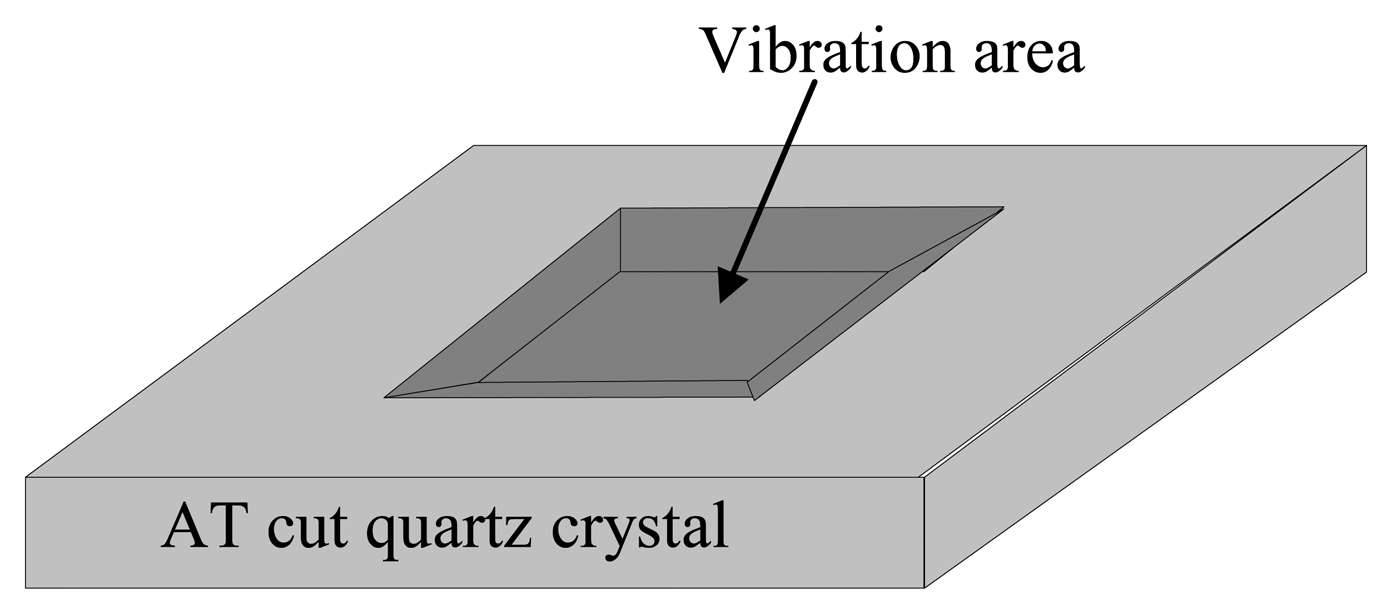
: In this study, a miniaturized high fundamental frequency quartz crystal microbalance (QCM) is fabricated for sensor applications using a wet etching technique. The vibration area is reduced in the fabrication of the high frequency QCM with an inverted mesa structure. To reduce the complexity of the side wall profile that results from anisotropic quartz etching, a rectangular vibration area is used instead of the conventional circular structure. QCMs with high Q values exceeding 25,000 at 47 MHz, 27,000 at 60 MHz, 24,000 at 73 MHz and 25,000 at 84 MHz are fabricated on 4 × 4 mm2 chips with small vibration areas of 1.2 × 1.4 mm2. A PMMA-based flow cell is designed and manufactured to characterize the behavior of the fabricated QCM chip in a liquid. Q values as high as 1,006 at 47 MHz, 904 at 62 MHz, 867 at 71 MHz and 747 at 84 MHz are obtained when one side of the chip is exposed to pure water. These results show that fabricated QCM chips can be used for bio- and chemical sensor applications in liquids.1. Introduction
A quartz crystal microbalance (QCM) is a common mass-sensitive tool that is widely used in chemical and bio-sensor applications. Generally, the QCM resonator functions in a thickness-shear-mode (TSM) vibration mode, and uses an AT-cut quartz crystal for its high temperature-frequency stability. The TSM resonator consists of a thin quartz crystal wafer with two metal excitation electrodes on each side. The QCM measures the frequency shift from the mass change on its surface in accordance with the famous Sauerbrey relation given below [1]:
2. Experimental Section
2.1. Design and Fabrication
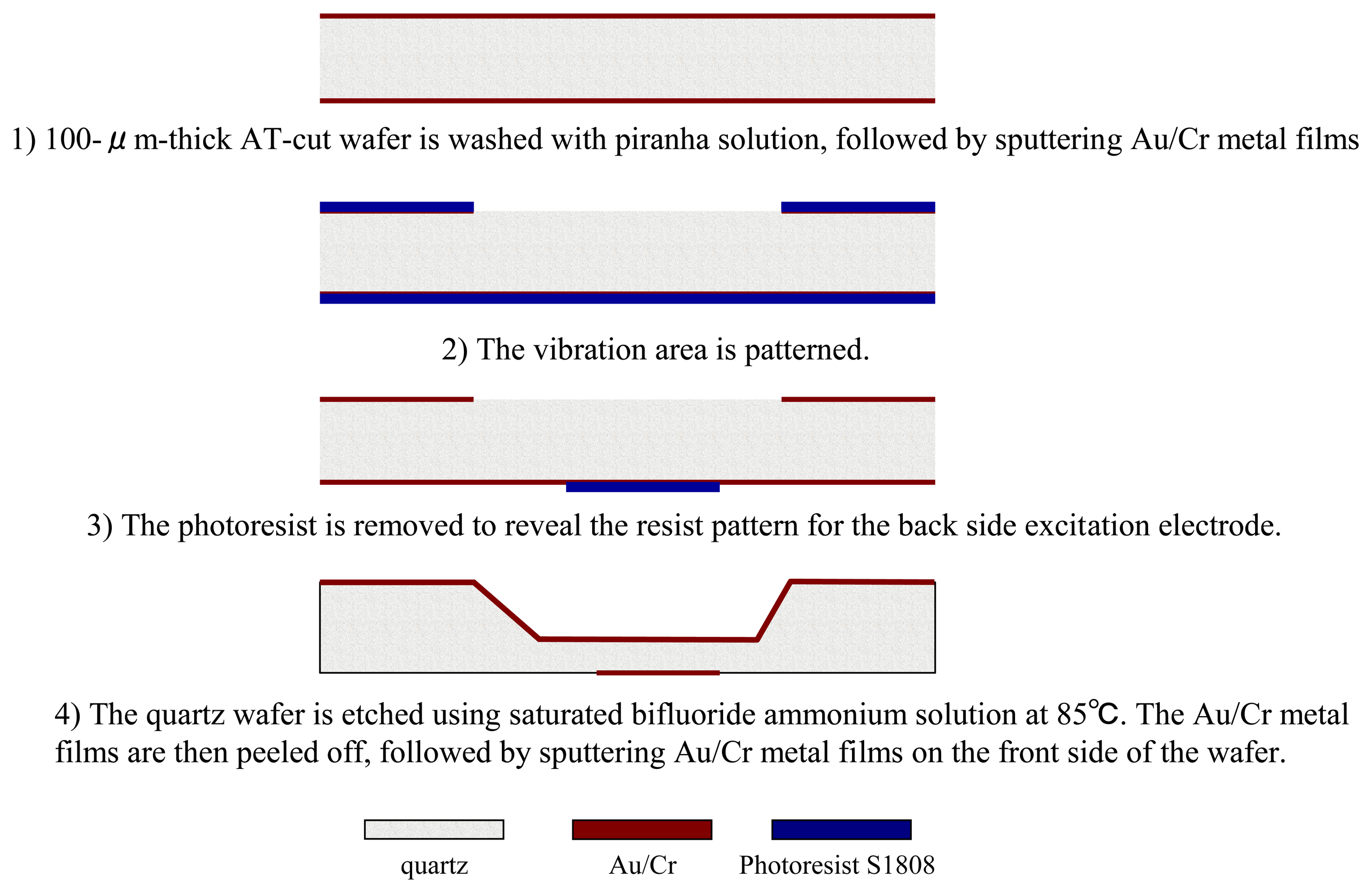
To facilitate mass-production and lower the fabrication costs of QCM chips, the design area of a single QCM chip is set at 4 × 4 mm2. The design etching area is 1.2 × 1.4 mm2. The initial AT cut wafer is 100 μm thick (to produce the resonance at 16.7 MHz frequency). The design dimensions of the excitation electrode on the front side of the chip range from 200 to 800 μm in diameter with a 100-μm interval. Figure 2 shows the detailed microfabrication process: (1) the quartz wafer is washed using a piranha solution (H2SO4: H2O2 = 3:1) at 110 °C, followed by sputtering Au/Cr (100 nm/40 nm) bi-layer metal films onto the wafer to form an etching mask; (2) Au/Cr metal layers are patterned on the back side of the wafer, followed by photoresist removal; (3) a resist pattern is formed on the front side of the wafer to serve as the front side excitation electrode; (4) the quartz wafer is wet-etched using a saturated ammonium bifluoride solution at 85 °C, followed by Au/Cr etching and photoresist removal treatment; (5) Au/Cr is sputtered on the back side of the wafer to form the back side excitation electrode.
2.2. Evaluation
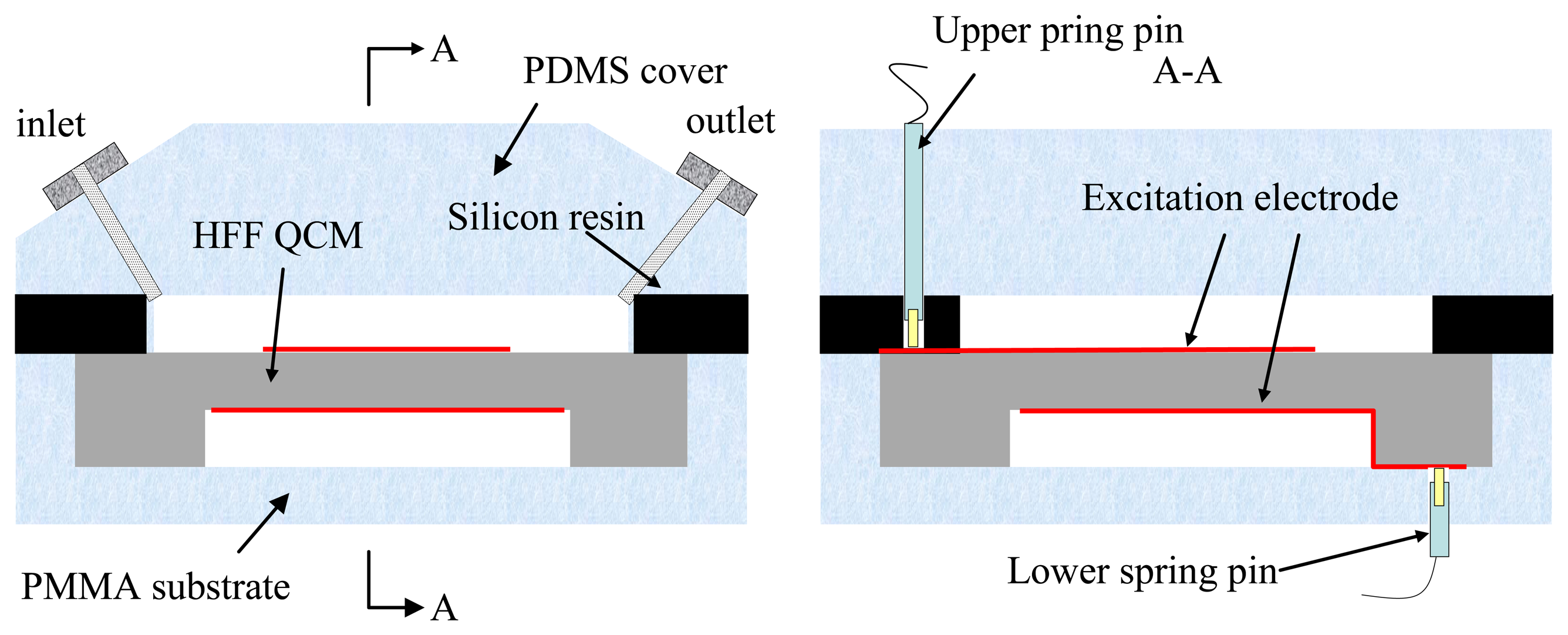
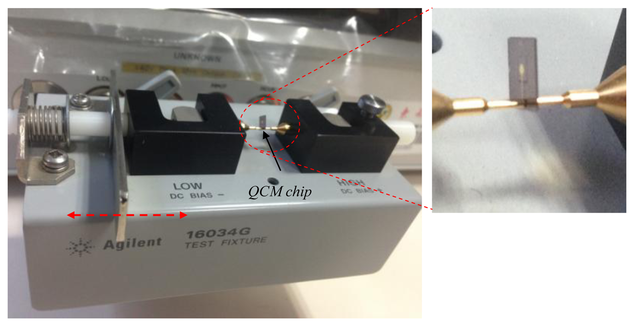
The vibration characteristics (i.e., the Q value, the equivalent circuit parameters, and the condition of the spurious modes near the primary TSM vibration) of the fabricated QCMs are directly evaluated by using an Agilent 4294A impedance analyzer with a 16034G test fixture, as shown in Figure 3. The sweep number is set to 800, and the scanning precision is set at the highest possible value. A flow cell is designed and fabricated to ensure that the chip can be used in practice as a bio- or chemical sensor in a liquid. The custom-designed flow cell consists of a PDMS cover, a thin silicon resin layer, and a PMMA substrate as shown in Figure 4. Liquid can be introduced through inlet and outlet ports in the PDMS cover. The silicon resin layer functions both as a sealing material and a cell chamber. A 100-μm deep cavity is created in the PMMA substrate to stabilize and hold the QCM chip. The excitation electrodes on the two sides of the chip are guided out using two spring-pins, each of which is fixed into a PDMS and PMMA substrate. A simple labview-based program is developed for data acquisition to examine the frequency stability and noise level.
3. Results and Discussion
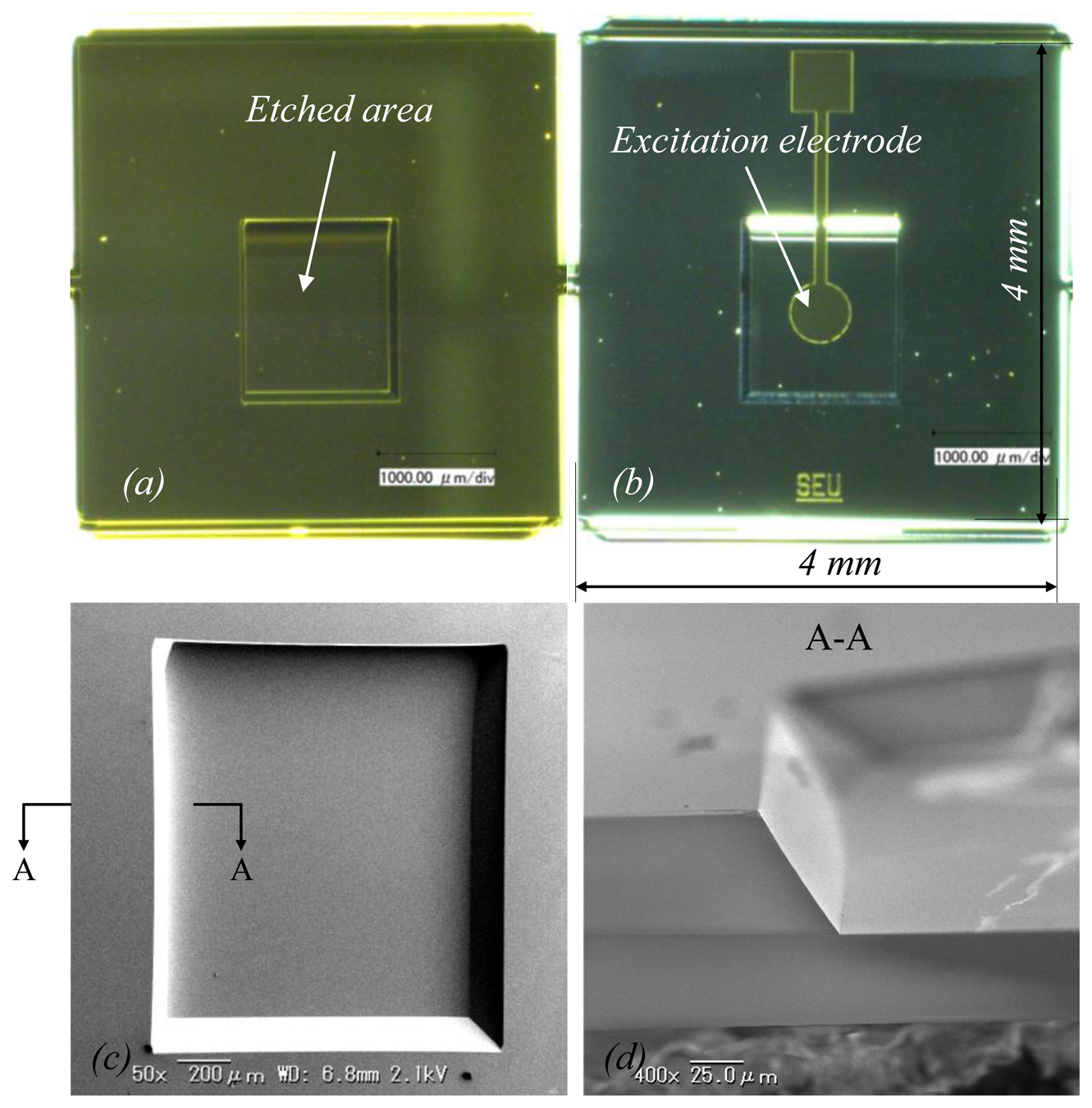
HFF QCMs of 47 MHz, 60 MHz, 73 MHz, and 84 MHz were obtained. Figure 5 shows a fabricated QCM. Figure 5a,b is optical images of the top view and back view of the QCM, respectively. Figure 5c is a close-up image of the etched rectangular area, and Figure 5d is a representative image of the etched side wall profile, which is much simpler than in the circular version.
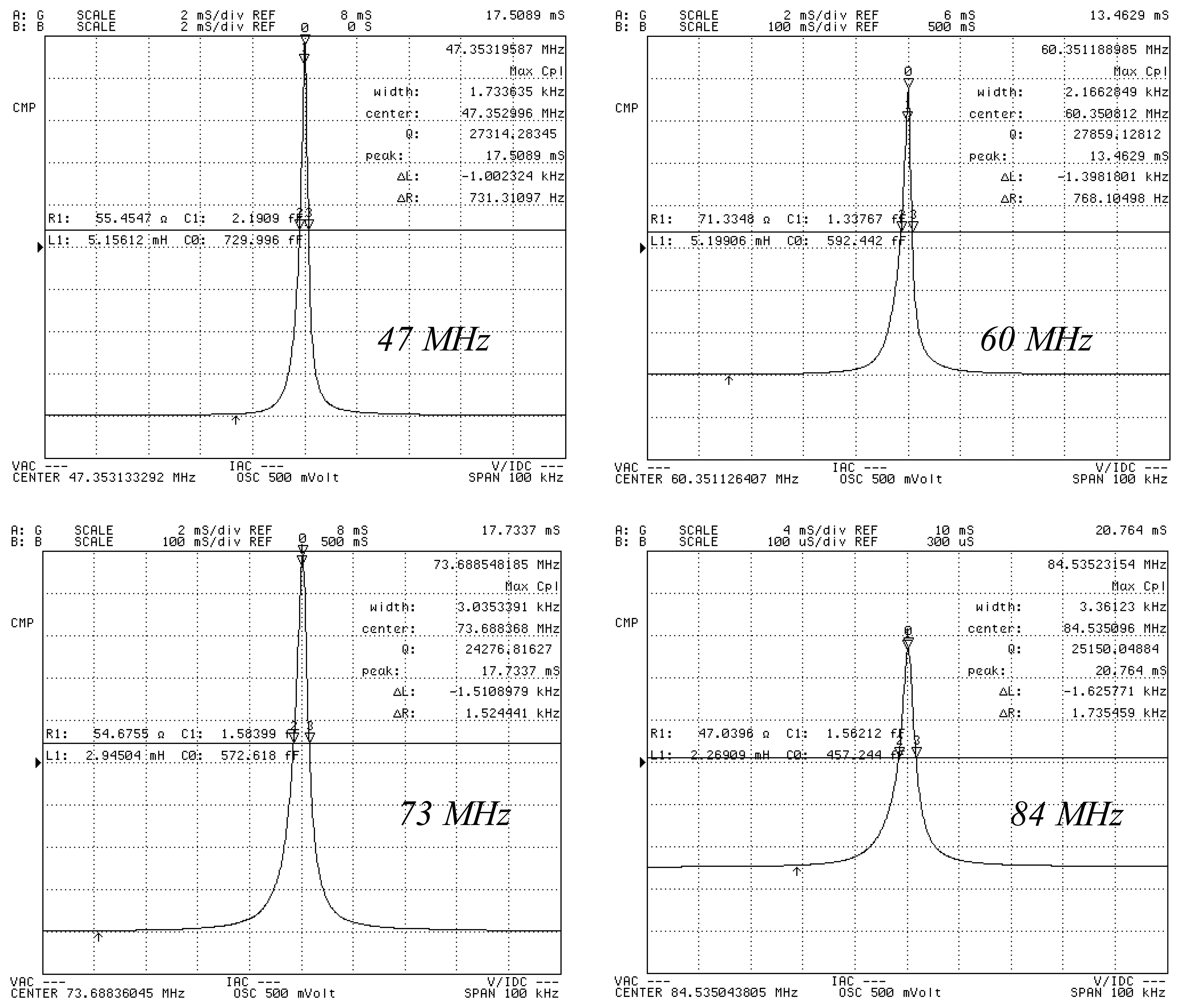
A high Q value, a low C0/C1-ratio and a low motional resistance are generally indicative of a high quality resonator [3]. Table 1 shows typical resonance parameters of a 73 MHz series, which are measured using a 4294A impedance analyzer with a 16034G test fixture, as an example.
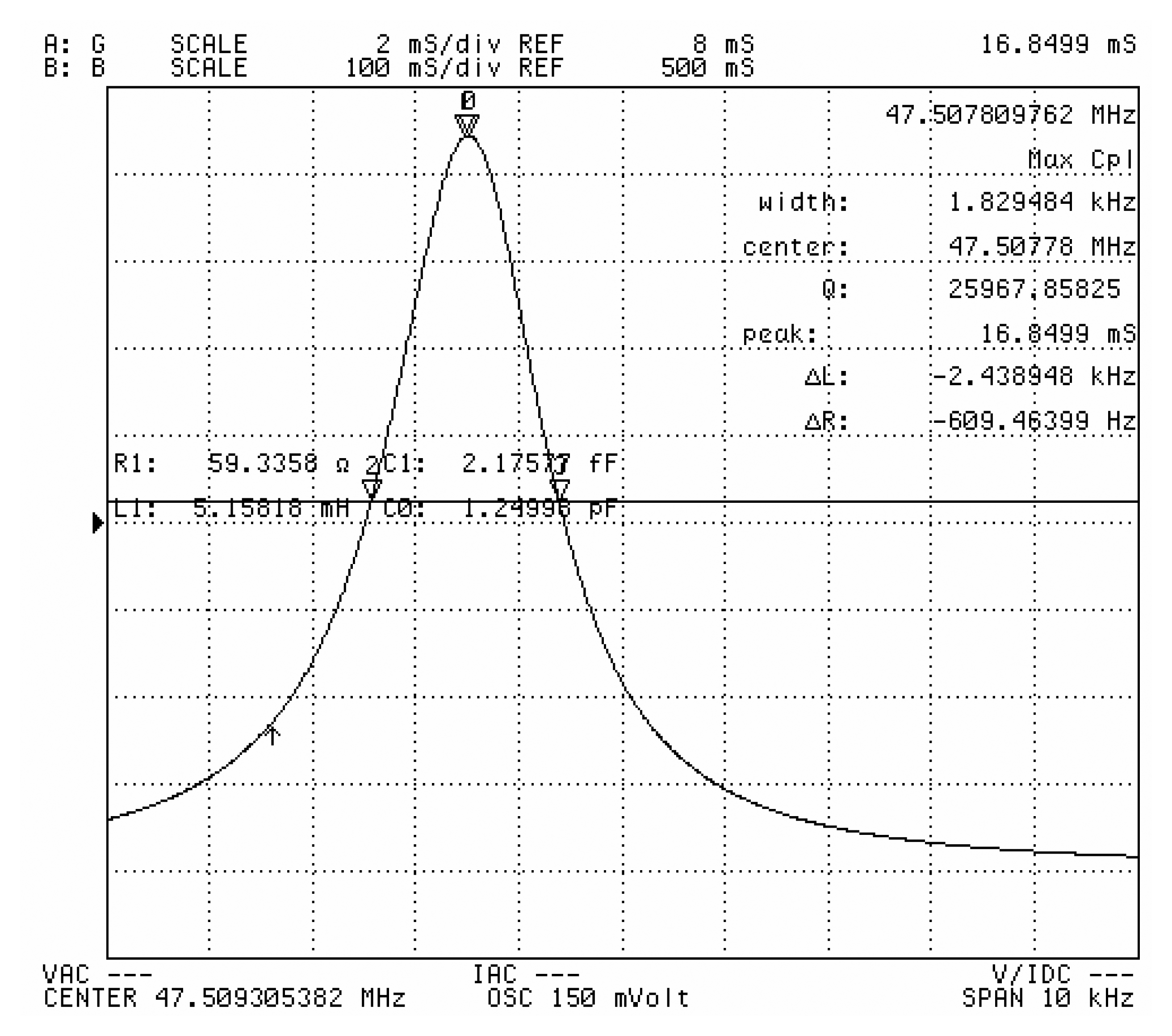
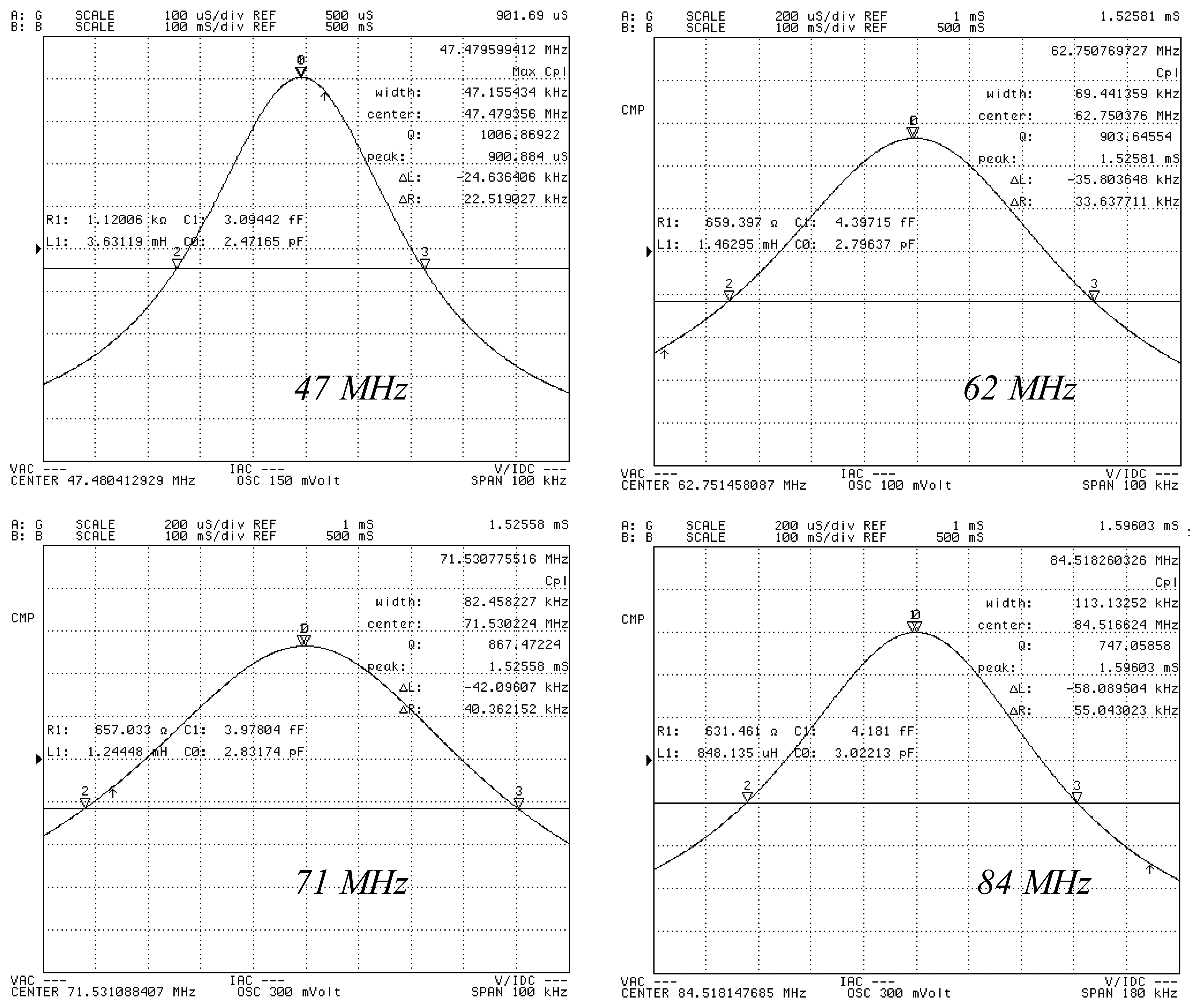
Herein, f represents the fundamental frequency, and R1, C1 and L1 represent the motional resistance, the motional capacitance, and motional inductance, respectively. C0 represents the shunt capacitance. Table 1 shows that the optimum electrode diameter for a QCM is 500 μm based on the aforementioned evaluation rule. For a given etching area (i.e., the vibration area), the optimal electrode dimension should be a tradeoff between the value from Shockley theory (i.e., the necessary separation between the electrode and the resonator boundary) and Bechmann's number (i.e., the electrode dimension required for energy trapping). For the 47 MHz, 60 MHz, and 84 MHz resonators, the QCM with the highest Q-factor QCM also has an electrode diameter of 500 μm. Figure 6 shows the measured conductance characteristics of the resonators, which are all measured as fabricated. Figure 7 shows the measured conductance characteristics of a 47 MHz QCM chip after it is assembled in the custom-designed flow cell. The Q value of the chip changes from 27,314 to 25,968, following assembly. Thus, the chip is not affected by the flow cell and the electrical leading spring pin. This result shows that the flow cell has been successfully designed and fabricated. Next, all of the four types of QCM chips are assembled in the flow cell, and pure water is flowed through the cell. Figure 8 shows the measured conductance characteristics of 47 MHz, 62 MHz, 71 MHz, and 84 MHz QCM chips in water. The Q values drop to 1,006 at 47 MHz, 904 at 62 MHz, 867 at 71 MHz, and 747 at 84 MHz respectively. The drop in the Q values can be attributed to the high viscosity of water. However, these Q values agree well with the calculated and experimental results in reference [14], and are acceptable for liquid applications according to previous reports [6,14].
All of the Q values of the fabricated high frequency TSM resonators in air exceed 20,000 and are therefore useful for sensor applications. Well known theoretical considerations show that the Q value of the TSM resonator is inversely proportional to the fundamental frequency, for example, a Q value of 25,000 for a 47 MHz resonator corresponds to a Q value of 235,000 for a 5 MHz resonator. In fact, it is very difficult to obtain such a high Q value with a conventional 5 MHz QCM, even for a large diameter of approximately 15 mm. The small size (especially in term of the vibration area size) of the fabricated high frequency resonator translates into a low cost for a single chip, and reduces the sample volume required which is advantageous for sensor applications with expensive or hazardous samples. Furthermore, the small size of a single resonator makes it possible to fabricate a QCM array on one chip for multiple analyses.
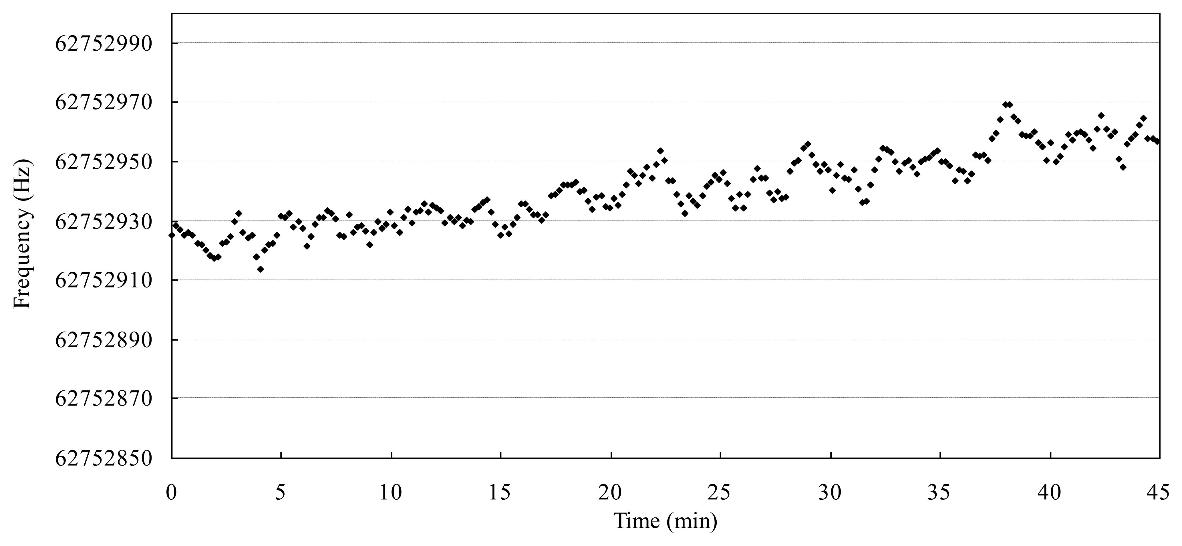
Figure 9 shows the measured frequency fluctuation of a 62 MHz resonator via 16,034G test fixture in air and room temperature. The frequency noise (defined as the standard deviation of frequency fluctuation) is measured to be 5 Hz over a period of 600 s (50 points) and the frequency drift (peak to peak) is about 50 Hz over a period of 45 min. The measured noise is higher than the previous reports [6,8,11], although the resonator has the similar mechanical vibration characteristics. Now we are making efforts to reduce the noise level in the following considerations. Firstly, a temperature stabilized chamber is needed to improve the unavoidable temperature noise and drift, which is usually used for precise measurement as above mentioned reports. Secondly, the data processing method should be developed instead of the commercial impedance analysis method [11,15]. Finally, a low bandwidth oscillator circuit is preferred instead of a broadband impedance analyzer [6,16].
4. Conclusions
High fundamental frequency QCMs with high Q values up to 25,000 for 47 MHz, 27,000 for 60 MHz, 24,000 for 73 MHz, and 25,000 for 84 MHz resonators were developed in this study. To our knowledge, ours is the first report on fabricating a QCM with an area below 4 × 4 mm2, and in particular with a small rectangular etching area of 1.2 × 1.4 mm2 using a cheap wet etching process. A PDMS micro-flow cell was designed and fabricated to test the fabricated HFF QCM chips. The flow cell was used to measure Q values of 1,006 at 47 MHz, 904 at 62 MHz, 867 at 71 MHz, and 747 at 84 MHz respectively in water, which are suitable for chemical, and bio-sensors applications in liquids.
Acknowledgments
Financial support for this work was provided by the Ph.D. Programs Foundation of the Ministry of Education of China (Grant No. 20110092120052), the Natural Science Foundation of Jiangsu Province (Grant No. BK2011607), and the Fundamental Research Funds for the Central Universities.
Conflicts of Interest
The authors declare no conflict of interest.
References
- Sauerbrey, G.Z. The use of quartz oscillators for weighing thin films and for microweighing. Z. Phys. 1959, 155, 206–222. [Google Scholar]
- Lin, Z.; Yip, C.M.; Joseph, I.S.; Ward, M.D. Operation of an ultrasensitive 30-MHz quartz crystal microbalance in liquids. Anal. Chem. 1993, 65, 1546–1551. [Google Scholar]
- Zimmermann, B.; Luchlum, R.; Hauptmann, P.; Rabe, J.; Büttgenbach, S. Electrical characterization of high-frequency thickness-shear-mode resonators by impedance analysis. Sens. Actuators B 2001, 76, 47–57. [Google Scholar]
- Rabe, J.; Büttgenbach, S.; Schröder, J.; Hauptmann, P. Monolithic miniaturized quartz microbalance array and its application to chemical sensor systems for liquids. IEEE Sens. J. 2003, 3, 361–368. [Google Scholar]
- Michalzik, M.; Wilke, R.; Büttgenbach, S. Miniaturized QCM-based flow system for immonosensor application in liquid. Sens. Actuators B 2005, 111–112, 410–415. [Google Scholar]
- Sagmeister, B.P.; Graz, I.M.; Schwödiauer, R.; Gruber, H.; Bauer, S. User-friendly, miniature biosensor flow cell for fragile high fundamental frequency quartz crystal resonators. Biosens. Bioelectron. 2009, 24, 2643–2648. [Google Scholar]
- Lederer, T.; Stehrer, B.P.; Bauer, S.; Jakoby, B.; Hiler, W. Utilizing a high fundamental frequency quartz crystal resonator as a biosensor in a digital microfluidic platform. Sens. Actuators A 2011, 172, 161–168. [Google Scholar]
- Williams, R.D.; Upadhyayula, A.K.; Bhethanabotla, V.R. High frequency thickness shear mode devices for organic vapor sensing. Sens. Actuators B 2007, 122, 635–643. [Google Scholar]
- Abe, T.; Hung, V.N.; Esashi, M. Inverted mesa-type quartz crystal resonators fabricated by deep-reactive ion etching. IEEE Trans. Ultrason. Ferroelectr. Freq. Control 2006, 53, 1234–1236. [Google Scholar]
- Hung, V.N.; Abe, T.; Minh, P.N.; Esashi, M. Miniaturized, highly sensitive single-chip multichannel quartz-crystal microbalance. Appl. Phys. Lett. 2002, 81, 5069–5071. [Google Scholar]
- Kao, P.; Doerner, S.; Schneider, T.; Allara, D. A micromachined quartz resonator array for biosensing applications. J. Microelectromech. Syst. 2009, 18, 522–530. [Google Scholar]
- Kao, P.; Patwardhan, A.; Allara, D.; Tadigadapa, S. Human serum albumin adsorption study on 62 MHz miniaturized quartz gravimetric sensors. Anal. Chem. 2008, 80, 5930–5936. [Google Scholar]
- Iwata, H. Miniaturized ultrahigh frequency fundamental quartz resonators. IEICE Electron. Express 2004, 1, 346–351. [Google Scholar]
- Kao, P.; Allara, D.; Tadigadapa, S. Fabrication and performance characteristics of high-frequency micromachined bulk acoustic wave quartz resonator arrays. Meas. Sci. Technol. 2009, 20, 124007. [Google Scholar]
- Qi, K.; Qi, Y.; Zhang, P.; Shen, D. Improve the signal-to-noise ratio of a quartz crystal microbalance in an impedance analysis method. Talanta 2007, 72, 1474–1480. [Google Scholar]
- Karousos, N.G.; Reddy, S.M. Determination of 4-aminophenol using the quartz crystal microbalance sensor. Analyst 2002, 127, 368–372. [Google Scholar]


| Parameters | Electrode Diameter (μm) | ||||||
|---|---|---|---|---|---|---|---|
| 200 | 300 | 400 | 500 | 600 | 700 | 800 | |
| f (MHz) | 73.67 | 73.99 | 72.54 | 73.68 | 71.59 | 73.09 | 70.42 |
| Q factor | 7,737 | 13,687 | 16,692 | 24,276 | 18,649 | 15,157 | 17,584 |
| R1 (Ω) | 406 | 157 | 77 | 55 | 43 | 40 | 32 |
| Υ(C0/C1) | 1,194 | 783 | 563 | 361 | 427 | 473 | 494 |
© 2013 by the authors; licensee MDPI, Basel, Switzerland. This article is an open access article distributed under the terms and conditions of the Creative Commons Attribution license (http://creativecommons.org/licenses/by/3.0/)
Share and Cite
Liang, J.; Huang, J.; Zhang, T.; Zhang, J.; Li, X.; Ueda, T. An Experimental Study on Fabricating an Inverted Mesa-Type Quartz Crystal Resonator Using a Cheap Wet Etching Process. Sensors 2013, 13, 12140-12148. https://doi.org/10.3390/s130912140
Liang J, Huang J, Zhang T, Zhang J, Li X, Ueda T. An Experimental Study on Fabricating an Inverted Mesa-Type Quartz Crystal Resonator Using a Cheap Wet Etching Process. Sensors. 2013; 13(9):12140-12148. https://doi.org/10.3390/s130912140
Chicago/Turabian StyleLiang, Jinxing, Jia Huang, Tian Zhang, Jing Zhang, Xuefeng Li, and Toshitsugu Ueda. 2013. "An Experimental Study on Fabricating an Inverted Mesa-Type Quartz Crystal Resonator Using a Cheap Wet Etching Process" Sensors 13, no. 9: 12140-12148. https://doi.org/10.3390/s130912140
APA StyleLiang, J., Huang, J., Zhang, T., Zhang, J., Li, X., & Ueda, T. (2013). An Experimental Study on Fabricating an Inverted Mesa-Type Quartz Crystal Resonator Using a Cheap Wet Etching Process. Sensors, 13(9), 12140-12148. https://doi.org/10.3390/s130912140