<?xml version="1.0" encoding="UTF-8"?>
<!DOCTYPE article PUBLIC "-//NLM//DTD Journal Publishing DTD v2.3 20070202//EN" "journalpublishing.dtd">
<article xmlns:mml="http://www.w3.org/1998/Math/MathML" xmlns:xlink="http://www.w3.org/1999/xlink" xml:lang="en" article-type="research-article">
<front>
<journal-meta>
<journal-id journal-id-type="nlm-ta">Sensors</journal-id>
<journal-title>Sensors</journal-title>
<issn pub-type="epub">1424-8220</issn>
<publisher>
<publisher-name>Molecular Diversity Preservation International (MDPI)</publisher-name></publisher></journal-meta>
<article-meta>
<article-id pub-id-type="doi">10.3390/s120709129</article-id>
<article-id pub-id-type="publisher-id">sensors-12-09129</article-id>
<article-categories>
<subj-group>
<subject>Article</subject></subj-group></article-categories>
<title-group>
<article-title>Performance Testing of a Magnetically Suspended Double Gimbal Control Moment Gyro Based on the Single Axis Air Bearing Table</article-title></title-group>
<contrib-group>
<contrib contrib-type="author">
<name><surname>Cui</surname><given-names>Peiling</given-names></name><xref ref-type="aff" rid="af1-sensors-12-09129"><sup>1</sup></xref><xref ref-type="aff" rid="af2-sensors-12-09129"><sup>2</sup></xref><xref ref-type="aff" rid="af3-sensors-12-09129"><sup>3</sup></xref><xref ref-type="corresp" rid="c1-sensors-12-09129"><sup>*</sup></xref></contrib>
<contrib contrib-type="author">
<name><surname>Zhang</surname><given-names>Huijuan</given-names></name><xref ref-type="aff" rid="af1-sensors-12-09129"><sup>1</sup></xref><xref ref-type="aff" rid="af2-sensors-12-09129"><sup>2</sup></xref><xref ref-type="aff" rid="af3-sensors-12-09129"><sup>3</sup></xref></contrib>
<contrib contrib-type="author">
<name><surname>Yan</surname><given-names>Ning</given-names></name><xref ref-type="aff" rid="af1-sensors-12-09129"><sup>1</sup></xref><xref ref-type="aff" rid="af2-sensors-12-09129"><sup>2</sup></xref><xref ref-type="aff" rid="af3-sensors-12-09129"><sup>3</sup></xref></contrib>
<contrib contrib-type="author">
<name><surname>Fang</surname><given-names>Jiancheng</given-names></name><xref ref-type="aff" rid="af1-sensors-12-09129"><sup>1</sup></xref><xref ref-type="aff" rid="af2-sensors-12-09129"><sup>2</sup></xref><xref ref-type="aff" rid="af3-sensors-12-09129"><sup>3</sup></xref></contrib></contrib-group>
<aff id="af1-sensors-12-09129">
<label>1</label> School of Instrumentation Science and Optoelectronics Engineering, Beijing University of Aeronautics and Astronautics, Beijing 100191, China; E-Mails: <email>zhanghjqy@126.com</email> (H.Z.); <email>n_yann@sina.com</email> (N.Y.); <email>fangjiancheng@buaa.edu.cn</email> (J.F.)</aff>
<aff id="af2-sensors-12-09129">
<label>2</label> Science and Technology on Inertial Laboratory, Beijing 100191, China</aff>
<aff id="af3-sensors-12-09129">
<label>3</label> Fundamental Science on Novel Inertial Instrument &amp; Navigation System Technology Laboratory, Beijing 100191, China</aff>
<author-notes>
<corresp id="c1-sensors-12-09129">
<label>*</label>Author to whom correspondence should be addressed; E-Mail: <email>peilingcui@buaa.edu.cn</email>; Tel.: +86-10-8233-9273.</corresp></author-notes>
<pub-date pub-type="collection">
<year>2012</year></pub-date>
<pub-date pub-type="epub">
<day>03</day>
<month>07</month>
<year>2012</year></pub-date>
<volume>12</volume>
<issue>7</issue>
<fpage>9129</fpage>
<lpage>9145</lpage>
<history>
<date date-type="received">
<day>17</day>
<month>04</month>
<year>2012</year></date>
<date date-type="rev-recd">
<day>18</day>
<month>06</month>
<year>2012</year></date>
<date date-type="accepted">
<day>21</day>
<month>06</month>
<year>2012</year></date></history>
<permissions>
<copyright-statement>© 2012 by the authors; licensee MDPI, Basel, Switzerland.</copyright-statement>
<copyright-year>2012</copyright-year>
<license>
<p>This article is an open access article distributed under the terms and conditions of the Creative Commons Attribution license (http://creativecommons.org/licenses/by/3.0/).</p></license></permissions>
<abstract>
<p>Integrating the advantage of magnetic bearings with a double gimble control moment gyroscope (DGCMG), a magnetically suspended DGCMG (MSDGCMG) is an ideal actuator in high-precision, long life, and rapid maneuver attitude control systems. The work presented here mainly focuses on performance testing of a MSDGCMG independently developed by Beihang University, based on the single axis air bearing table. In this paper, taking into sufficient consideration to the moving-gimbal effects and the response bandwidth limit of the gimbal, a special MSDGCMG steering law is proposed subject to the limits of gimbal angle rate and angle acceleration. Finally, multiple experiments are carried out, with different MSDGCMG angular momenta as well as different desired attitude angles. The experimental results indicate that the MSDGCMG has a good gimbal angle rate and output torque tracking capabilities, and that the attitude stability with MSDGCMG as actuator is superior to 10<sup>−3</sup>°/s. The MSDGCMG performance testing in this paper, carried out under moving-base condition, will offer a technique base for the future research and application of MSDGCMGs.</p></abstract>
<kwd-group>
<kwd>magnetically suspended double gimbal control moment gyroscope (MSDGCMG)</kwd>
<kwd>attitude control</kwd>
<kwd>single axis air bearing table</kwd>
<kwd>experiment</kwd></kwd-group></article-meta></front>
<body>
<sec sec-type="intro">
<label>1.</label>
<title>Introduction</title>
<p>Because a control moment gyroscope (CMG) is capable of generating large control torques and storing large angular momentum over long periods of time, it is often favored for precision pointing and tracking control of agile spacecraft in low Earth orbit and momentum management of large space vehicles [<xref ref-type="bibr" rid="b1-sensors-12-09129">1</xref>,<xref ref-type="bibr" rid="b2-sensors-12-09129">2</xref>]. Depending on the gimbal axes, a CMG is distinguished as either a single gimbal CMG (SGCMG) or double gimbal CMG (DGCMG) [<xref ref-type="bibr" rid="b3-sensors-12-09129">3</xref>]. Compared with SGCMG, DGCMG has many advantages such as the output control torques with two degrees of freedom, nearly spherical angular momentum envelope, good configuration efficiency, no striking singularity problem, low steering law computation complexity, and so on. Meanwhile, the compatibility of the steering law is quite good when part of the DGCMGs fail [<xref ref-type="bibr" rid="b4-sensors-12-09129">4</xref>,<xref ref-type="bibr" rid="b5-sensors-12-09129">5</xref>].</p>
<p>The manner of support of the high-rate rotor is a deciding factor in the comprehensive performance of a CMG [<xref ref-type="bibr" rid="b6-sensors-12-09129">6</xref>]. Considering the manner of support, CMGs are divided into mechanical CMGs and magnetically suspended CMGs (MSCMGs). In comparison with the mechanical CMGs, MSCMGs have the merits of being friction-free, long life, and so on. Meanwhile, the control accuracy is improved by active vibration control techniques. With the same angular momentum, the size and weight of a CMG is effectively reduced for the reason of a high-rate magnetically suspended rotor [<xref ref-type="bibr" rid="b7-sensors-12-09129">7</xref>,<xref ref-type="bibr" rid="b8-sensors-12-09129">8</xref>]. Incorporating the advantage of magnetic bearings with that of DGCMGs, magnetically suspended DGCMGs (MSDGCMG) will become an ideal solution to realize high precision, long life, and rapid maneuver attitude control for spacecraft.</p>
<p>In the 1960s, the US devoted itself to the research and development of DGCMGs. In 1973, three orthogonally mounted DGCMGs were firstly employed on NASA's Skylab as the main actuator [<xref ref-type="bibr" rid="b9-sensors-12-09129">9</xref>–<xref ref-type="bibr" rid="b11-sensors-12-09129">11</xref>], and four parallel mounted DGCMGs were applied on the International Space Station (ISS) in 1998 [<xref ref-type="bibr" rid="b12-sensors-12-09129">12</xref>–<xref ref-type="bibr" rid="b14-sensors-12-09129">14</xref>]. Up to the present, DGCMGs have been successfully employed for a variety of space missions. However, the related research in the open literature on attitude control systems with DGCMGs as attitude actuators was based on mechanical-bearing DGCMGs. In the aspect of the investigation of MSDGCMG, Beihang University has been devoted to developing the MSDGCMG since 1998, and has successfully developed the first MSDGCMG in the world. Up to the present, all the research on MSDGCMG is carried out on the resting base. They include: optimization design of a magnetic suspended gyroscope rotor [<xref ref-type="bibr" rid="b6-sensors-12-09129">6</xref>], compensation of moving-gimbal effects [<xref ref-type="bibr" rid="b15-sensors-12-09129">15</xref>], AMB vibration control for structural resonance [<xref ref-type="bibr" rid="b16-sensors-12-09129">16</xref>], and so on. However, there still exist various practical as well as theoretical issues inherent in the performance of MSDGCMGs installed on the moving-base and the use of MSDGCMGs for attitude control.</p>
<p>In this paper, we focus our attention on the performance test of MSDGCMGs under the moving-base condition, such as gimbal angle rate and MSDGCMG output torque tracking capacity as well as attitude stability with an MSDGCMG as an attitude actuator. The remainder of this paper is organized as follows: Section 2 briefly introduces the mathematical model of the single axis air bearing table. In Section 3, a parameter segment control law is used for the rapid maneuver and quick stability subjected to the control torque saturation. In view of the moving-gimbal effect on the stability of the magnetic bearing and the response bandwidth limit of the MSDGCMG gimbal, Section 4 presents a special steering law subject to the constraints of MSDGCMG gimbal angle rate and acceleration. Section 5 gives a detailed description of the semi-physical simulation platform of the MSDGCMG performance testing experiments. In Section 6, experiments and the corresponding results analysis are given in detail. Finally, some conclusions are drawn in Section 7.</p></sec>
<sec>
<label>2.</label>
<title>Mathematical Model of the Single Axis Air Bearing Table</title>
<p>The objective of this section is to give a mathematical model of the single axis air bearing table for developing the attitude control law in the next section. The models are introduced as follows, including the dynamic model and the error quaternion kinematics differential equation.</p>
<sec>
<label>2.1.</label>
<title>Dynamic Model of the Single Axis Air Bearing Table</title>
<p>In the experiment, the single axis air bearing table is utilized for simulating the rotational motion of a certain physical axis of the satellite, and according to the feature of large angle and rapid maneuver, the pitch axis (<italic>Y</italic>) is chosen as the physical axis. The dynamic model of the single axis air bearing table is governed by the following differential equation:
<disp-formula id="FD1">
<label>(1)</label>
<mml:math id="mm1" display="block">
<mml:semantics id="sm1">
<mml:mrow>
<mml:mi>J</mml:mi>
<mml:mover accent="true">
<mml:mi>ω</mml:mi>
<mml:mo>˙</mml:mo></mml:mover>
<mml:mo>=</mml:mo>
<mml:mi>u</mml:mi>
<mml:mo>+</mml:mo>
<mml:msub>
<mml:mi>T</mml:mi>
<mml:mi>d</mml:mi></mml:msub></mml:mrow></mml:semantics></mml:math></disp-formula>where <italic>ω</italic> denotes the air bearing table rotation angle rate, <italic>J</italic> is the moment of inertia of the air bearing table, <italic>u</italic> is the control torque input, and <italic>T<sub>d</sub></italic> is the disturbance torque.</p></sec>
<sec>
<label>2.2.</label>
<title>Kinematics Equation of the Single Axis Air Bearing Table</title>
<p>Assuming that the “3-1-2” Euler angle rotation is adopted, the relationship between the attitude quaternion and Euler angle is described as follows:
<disp-formula id="FD2">
<label>(2)</label>
<mml:math id="mm2" display="block">
<mml:semantics id="sm2">
<mml:mrow>
<mml:mi>q</mml:mi>
<mml:mo>=</mml:mo>
<mml:mrow>
<mml:mo>[</mml:mo>
<mml:mrow>
<mml:mtable>
<mml:mtr>
<mml:mtd>
<mml:mrow>
<mml:msub>
<mml:mi>q</mml:mi>
<mml:mn>0</mml:mn></mml:msub></mml:mrow></mml:mtd></mml:mtr>
<mml:mtr>
<mml:mtd>
<mml:mrow>
<mml:msub>
<mml:mi>q</mml:mi>
<mml:mn>1</mml:mn></mml:msub></mml:mrow></mml:mtd></mml:mtr>
<mml:mtr>
<mml:mtd>
<mml:mrow>
<mml:msub>
<mml:mi>q</mml:mi>
<mml:mn>2</mml:mn></mml:msub></mml:mrow></mml:mtd></mml:mtr>
<mml:mtr>
<mml:mtd>
<mml:mrow>
<mml:msub>
<mml:mi>q</mml:mi>
<mml:mn>3</mml:mn></mml:msub></mml:mrow></mml:mtd></mml:mtr></mml:mtable></mml:mrow>
<mml:mo>]</mml:mo></mml:mrow>
<mml:mo>=</mml:mo>
<mml:mrow>
<mml:mo>[</mml:mo>
<mml:mtable columnalign="left">
<mml:mtr>
<mml:mtd>
<mml:mo>cos</mml:mo>
<mml:mfrac>
<mml:mi>φ</mml:mi>
<mml:mn>2</mml:mn></mml:mfrac>
<mml:mo>cos</mml:mo>
<mml:mfrac>
<mml:mi>θ</mml:mi>
<mml:mn>2</mml:mn></mml:mfrac>
<mml:mo>cos</mml:mo>
<mml:mfrac>
<mml:mi>ψ</mml:mi>
<mml:mn>2</mml:mn></mml:mfrac>
<mml:mo>−</mml:mo>
<mml:mo>sin</mml:mo>
<mml:mfrac>
<mml:mi>φ</mml:mi>
<mml:mn>2</mml:mn></mml:mfrac>
<mml:mo>sin</mml:mo>
<mml:mfrac>
<mml:mi>θ</mml:mi>
<mml:mn>2</mml:mn></mml:mfrac>
<mml:mo>sin</mml:mo>
<mml:mfrac>
<mml:mi>ψ</mml:mi>
<mml:mn>2</mml:mn></mml:mfrac></mml:mtd></mml:mtr>
<mml:mtr>
<mml:mtd>
<mml:mo>sin</mml:mo>
<mml:mfrac>
<mml:mi>φ</mml:mi>
<mml:mn>2</mml:mn></mml:mfrac>
<mml:mo>cos</mml:mo>
<mml:mfrac>
<mml:mi>θ</mml:mi>
<mml:mn>2</mml:mn></mml:mfrac>
<mml:mo>cos</mml:mo>
<mml:mfrac>
<mml:mi>ψ</mml:mi>
<mml:mn>2</mml:mn></mml:mfrac>
<mml:mo>−</mml:mo>
<mml:mo>cos</mml:mo>
<mml:mfrac>
<mml:mi>φ</mml:mi>
<mml:mn>2</mml:mn></mml:mfrac>
<mml:mo>sin</mml:mo>
<mml:mfrac>
<mml:mi>θ</mml:mi>
<mml:mn>2</mml:mn></mml:mfrac>
<mml:mo>sin</mml:mo>
<mml:mfrac>
<mml:mi>ψ</mml:mi>
<mml:mn>2</mml:mn></mml:mfrac></mml:mtd></mml:mtr>
<mml:mtr>
<mml:mtd>
<mml:mo>cos</mml:mo>
<mml:mfrac>
<mml:mi>φ</mml:mi>
<mml:mn>2</mml:mn></mml:mfrac>
<mml:mo>sin</mml:mo>
<mml:mfrac>
<mml:mi>θ</mml:mi>
<mml:mn>2</mml:mn></mml:mfrac>
<mml:mo>cos</mml:mo>
<mml:mfrac>
<mml:mi>ψ</mml:mi>
<mml:mn>2</mml:mn></mml:mfrac>
<mml:mo>+</mml:mo>
<mml:mo>sin</mml:mo>
<mml:mfrac>
<mml:mi>φ</mml:mi>
<mml:mn>2</mml:mn></mml:mfrac>
<mml:mo>cos</mml:mo>
<mml:mfrac>
<mml:mi>θ</mml:mi>
<mml:mn>2</mml:mn></mml:mfrac>
<mml:mo>sin</mml:mo>
<mml:mfrac>
<mml:mi>ψ</mml:mi>
<mml:mn>2</mml:mn></mml:mfrac></mml:mtd></mml:mtr>
<mml:mtr>
<mml:mtd>
<mml:mo>sin</mml:mo>
<mml:mfrac>
<mml:mi>φ</mml:mi>
<mml:mn>2</mml:mn></mml:mfrac>
<mml:mo>sin</mml:mo>
<mml:mfrac>
<mml:mi>θ</mml:mi>
<mml:mn>2</mml:mn></mml:mfrac>
<mml:mo>cos</mml:mo>
<mml:mfrac>
<mml:mi>ψ</mml:mi>
<mml:mn>2</mml:mn></mml:mfrac>
<mml:mo>+</mml:mo>
<mml:mo>cos</mml:mo>
<mml:mfrac>
<mml:mi>φ</mml:mi>
<mml:mn>2</mml:mn></mml:mfrac>
<mml:mo>cos</mml:mo>
<mml:mfrac>
<mml:mi>θ</mml:mi>
<mml:mn>2</mml:mn></mml:mfrac>
<mml:mo>sin</mml:mo>
<mml:mfrac>
<mml:mi>ψ</mml:mi>
<mml:mn>2</mml:mn></mml:mfrac></mml:mtd></mml:mtr></mml:mtable>
<mml:mo>]</mml:mo></mml:mrow></mml:mrow></mml:semantics></mml:math></disp-formula>where <italic>q</italic><sub>0</sub> denotes the scalar part of the quaternion, <italic>q̄</italic> = [<italic>q</italic><sub>1</sub> <italic>q</italic><sub>2</sub> <italic>q</italic><sub>3</sub>]<italic><sup>T</sup></italic> is the vector part of the quaternion. <italic>φ, θ</italic> and <italic>ψ</italic> denote the roll, pitch and yaw angle, respectively. Considering the case of <italic>φ</italic> = <italic>0</italic> and <italic>ψ</italic> = <italic>0</italic> for the single axis air bearing table, then the attitude of the air bearing table is rewritten in the form of quaternion as follows:
<disp-formula id="FD3">
<label>(3)</label>
<mml:math id="mm3" display="block">
<mml:semantics id="sm3">
<mml:mrow>
<mml:mi>q</mml:mi>
<mml:mo>=</mml:mo>
<mml:msup>
<mml:mrow>
<mml:mrow>
<mml:mo>[</mml:mo>
<mml:mrow>
<mml:mtable>
<mml:mtr>
<mml:mtd>
<mml:mrow>
<mml:mo>cos</mml:mo>
<mml:mfrac>
<mml:mi>θ</mml:mi>
<mml:mn>2</mml:mn></mml:mfrac></mml:mrow></mml:mtd>
<mml:mtd>
<mml:mn>0</mml:mn></mml:mtd>
<mml:mtd>
<mml:mrow>
<mml:mo>sin</mml:mo>
<mml:mfrac>
<mml:mi>θ</mml:mi>
<mml:mn>2</mml:mn></mml:mfrac></mml:mrow></mml:mtd>
<mml:mtd>
<mml:mn>0</mml:mn></mml:mtd></mml:mtr></mml:mtable></mml:mrow>
<mml:mo>]</mml:mo></mml:mrow></mml:mrow>
<mml:mi>T</mml:mi></mml:msup></mml:mrow></mml:semantics></mml:math></disp-formula></p>
<p>If the Euler angle <italic>θ<sub>c</sub></italic> defines the command air bearing table rotation angle, the corresponding command attitude quaternion is given as:
<disp-formula id="FD4">
<label>(4)</label>
<mml:math id="mm4" display="block">
<mml:semantics id="sm4">
<mml:mrow>
<mml:msub>
<mml:mi>q</mml:mi>
<mml:mi>c</mml:mi></mml:msub>
<mml:mo>=</mml:mo>
<mml:msup>
<mml:mrow>
<mml:mrow>
<mml:mo>[</mml:mo>
<mml:mrow>
<mml:mtable>
<mml:mtr>
<mml:mtd>
<mml:mrow>
<mml:msub>
<mml:mi>q</mml:mi>
<mml:mrow>
<mml:mi>c</mml:mi>
<mml:mn>0</mml:mn></mml:mrow></mml:msub></mml:mrow></mml:mtd>
<mml:mtd>
<mml:mrow>
<mml:msubsup>
<mml:mover accent="true">
<mml:mi>q</mml:mi>
<mml:mo>¯</mml:mo></mml:mover>
<mml:mi>c</mml:mi>
<mml:mi>T</mml:mi></mml:msubsup></mml:mrow></mml:mtd></mml:mtr></mml:mtable></mml:mrow>
<mml:mo>]</mml:mo></mml:mrow></mml:mrow>
<mml:mi>T</mml:mi></mml:msup>
<mml:mo>=</mml:mo>
<mml:msup>
<mml:mrow>
<mml:mrow>
<mml:mo>[</mml:mo>
<mml:mrow>
<mml:mtable>
<mml:mtr>
<mml:mtd>
<mml:mrow>
<mml:mo>cos</mml:mo>
<mml:mfrac>
<mml:mrow>
<mml:msub>
<mml:mi>θ</mml:mi>
<mml:mi>c</mml:mi></mml:msub></mml:mrow>
<mml:mn>2</mml:mn></mml:mfrac></mml:mrow></mml:mtd>
<mml:mtd>
<mml:mn>0</mml:mn></mml:mtd>
<mml:mtd>
<mml:mrow>
<mml:mo>sin</mml:mo>
<mml:mfrac>
<mml:mrow>
<mml:msub>
<mml:mi>θ</mml:mi>
<mml:mi>c</mml:mi></mml:msub></mml:mrow>
<mml:mn>2</mml:mn></mml:mfrac></mml:mrow></mml:mtd>
<mml:mtd>
<mml:mn>0</mml:mn></mml:mtd></mml:mtr></mml:mtable></mml:mrow>
<mml:mo>]</mml:mo></mml:mrow></mml:mrow>
<mml:mi>T</mml:mi></mml:msup></mml:mrow></mml:semantics></mml:math></disp-formula></p>
<p>Then the error quaternion, which represents the error between the current attitude quaternion and the command attitude quaternion, is defined as:
<disp-formula id="FD5">
<label>(5)</label>
<mml:math id="mm5" display="block">
<mml:semantics id="sm5">
<mml:mrow>
<mml:msub>
<mml:mi>q</mml:mi>
<mml:mrow>
<mml:mi>e</mml:mi>
<mml:mi>v</mml:mi></mml:mrow></mml:msub>
<mml:mo>=</mml:mo>
<mml:mrow>
<mml:mo>[</mml:mo>
<mml:mrow>
<mml:mtable>
<mml:mtr>
<mml:mtd>
<mml:mrow>
<mml:msub>
<mml:mi>q</mml:mi>
<mml:mrow>
<mml:mi>c</mml:mi>
<mml:mn>0</mml:mn></mml:mrow></mml:msub></mml:mrow></mml:mtd>
<mml:mtd>
<mml:mrow>
<mml:msubsup>
<mml:mover accent="true">
<mml:mi>q</mml:mi>
<mml:mo>¯</mml:mo></mml:mover>
<mml:mi>c</mml:mi>
<mml:mi>T</mml:mi></mml:msubsup></mml:mrow></mml:mtd></mml:mtr>
<mml:mtr>
<mml:mtd>
<mml:mrow>
<mml:mo>−</mml:mo>
<mml:msub>
<mml:mover accent="true">
<mml:mi>q</mml:mi>
<mml:mo>¯</mml:mo></mml:mover>
<mml:mi>c</mml:mi></mml:msub></mml:mrow></mml:mtd>
<mml:mtd>
<mml:mrow>
<mml:mo>−</mml:mo>
<mml:mrow>
<mml:mo>[</mml:mo>
<mml:mrow>
<mml:msub>
<mml:mover accent="true">
<mml:mi>q</mml:mi>
<mml:mo>¯</mml:mo></mml:mover>
<mml:mi>c</mml:mi></mml:msub>
<mml:mo>×</mml:mo></mml:mrow>
<mml:mo>]</mml:mo></mml:mrow>
<mml:mo>+</mml:mo>
<mml:msub>
<mml:mi>q</mml:mi>
<mml:mrow>
<mml:mi>c</mml:mi>
<mml:mn>0</mml:mn></mml:mrow></mml:msub>
<mml:msub>
<mml:mi>I</mml:mi>
<mml:mrow>
<mml:mn>3</mml:mn>
<mml:mo>×</mml:mo>
<mml:mn>3</mml:mn></mml:mrow></mml:msub></mml:mrow></mml:mtd></mml:mtr></mml:mtable></mml:mrow>
<mml:mo>]</mml:mo></mml:mrow>
<mml:mi>q</mml:mi></mml:mrow></mml:semantics></mml:math></disp-formula></p>
<p>Substituting (<xref rid="FD3" ref-type="disp-formula">3</xref>) and (<xref rid="FD4" ref-type="disp-formula">4</xref>) into (<xref rid="FD5" ref-type="disp-formula">5</xref>) gives the error quaternion:
<disp-formula id="FD6">
<label>(6)</label>
<mml:math id="mm6" display="block">
<mml:semantics id="sm6">
<mml:mrow>
<mml:msub>
<mml:mi>q</mml:mi>
<mml:mrow>
<mml:mi>e</mml:mi>
<mml:mi>v</mml:mi></mml:mrow></mml:msub>
<mml:mo>=</mml:mo>
<mml:mrow>
<mml:mo>[</mml:mo>
<mml:mrow>
<mml:mtable>
<mml:mtr>
<mml:mtd>
<mml:mrow>
<mml:msub>
<mml:mi>q</mml:mi>
<mml:mrow>
<mml:mi>e</mml:mi>
<mml:mn>0</mml:mn></mml:mrow></mml:msub></mml:mrow></mml:mtd></mml:mtr>
<mml:mtr>
<mml:mtd>
<mml:mrow>
<mml:msub>
<mml:mi>q</mml:mi>
<mml:mrow>
<mml:mi>e</mml:mi>
<mml:mn>1</mml:mn></mml:mrow></mml:msub></mml:mrow></mml:mtd></mml:mtr>
<mml:mtr>
<mml:mtd>
<mml:mrow>
<mml:msub>
<mml:mi>q</mml:mi>
<mml:mrow>
<mml:mi>e</mml:mi>
<mml:mn>2</mml:mn></mml:mrow></mml:msub></mml:mrow></mml:mtd></mml:mtr>
<mml:mtr>
<mml:mtd>
<mml:mrow>
<mml:msub>
<mml:mi>q</mml:mi>
<mml:mrow>
<mml:mi>e</mml:mi>
<mml:mn>3</mml:mn></mml:mrow></mml:msub></mml:mrow></mml:mtd></mml:mtr></mml:mtable></mml:mrow>
<mml:mo>]</mml:mo></mml:mrow>
<mml:mo>=</mml:mo>
<mml:mrow>
<mml:mo>[</mml:mo>
<mml:mrow>
<mml:mtable>
<mml:mtr>
<mml:mtd>
<mml:mrow>
<mml:mo>cos</mml:mo>
<mml:mo stretchy="false">(</mml:mo>
<mml:mfrac>
<mml:mrow>
<mml:mi>θ</mml:mi>
<mml:mo>−</mml:mo>
<mml:msub>
<mml:mi>θ</mml:mi>
<mml:mi>c</mml:mi></mml:msub></mml:mrow>
<mml:mn>2</mml:mn></mml:mfrac>
<mml:mo stretchy="false">)</mml:mo></mml:mrow></mml:mtd></mml:mtr>
<mml:mtr>
<mml:mtd>
<mml:mn>0</mml:mn></mml:mtd></mml:mtr>
<mml:mtr>
<mml:mtd>
<mml:mrow>
<mml:mo>sin</mml:mo>
<mml:mo stretchy="false">(</mml:mo>
<mml:mfrac>
<mml:mrow>
<mml:mi>θ</mml:mi>
<mml:mo>−</mml:mo>
<mml:msub>
<mml:mi>θ</mml:mi>
<mml:mi>c</mml:mi></mml:msub></mml:mrow>
<mml:mn>2</mml:mn></mml:mfrac>
<mml:mo stretchy="false">)</mml:mo></mml:mrow></mml:mtd></mml:mtr>
<mml:mtr>
<mml:mtd>
<mml:mn>0</mml:mn></mml:mtd></mml:mtr></mml:mtable></mml:mrow>
<mml:mo>]</mml:mo></mml:mrow></mml:mrow></mml:semantics></mml:math></disp-formula>and then the error quaternion kinematics differential equation is expressed as:
<disp-formula id="FD7">
<label>(7)</label>
<mml:math id="mm7" display="block">
<mml:semantics id="sm7">
<mml:mrow>
<mml:msub>
<mml:mover accent="true">
<mml:mi>q</mml:mi>
<mml:mo>˙</mml:mo></mml:mover>
<mml:mrow>
<mml:mi>e</mml:mi>
<mml:mi>v</mml:mi></mml:mrow></mml:msub>
<mml:mo>=</mml:mo>
<mml:mfrac>
<mml:mn>1</mml:mn>
<mml:mn>2</mml:mn></mml:mfrac>
<mml:mrow>
<mml:mo>[</mml:mo>
<mml:mtable>
<mml:mtr>
<mml:mtd>
<mml:mo>−</mml:mo>
<mml:msub>
<mml:mi>q</mml:mi>
<mml:mrow>
<mml:mi>e</mml:mi>
<mml:mn>2</mml:mn></mml:mrow></mml:msub>
<mml:mo>⋅</mml:mo>
<mml:mi>ω</mml:mi></mml:mtd></mml:mtr>
<mml:mtr>
<mml:mtd>
<mml:mn>0</mml:mn></mml:mtd></mml:mtr>
<mml:mtr>
<mml:mtd>
<mml:msub>
<mml:mi>q</mml:mi>
<mml:mrow>
<mml:mi>e</mml:mi>
<mml:mn>0</mml:mn></mml:mrow></mml:msub>
<mml:mo>⋅</mml:mo>
<mml:mi>ω</mml:mi></mml:mtd></mml:mtr>
<mml:mtr>
<mml:mtd>
<mml:mn>0</mml:mn></mml:mtd></mml:mtr></mml:mtable>
<mml:mo>]</mml:mo></mml:mrow>
<mml:mo>=</mml:mo>
<mml:mrow>
<mml:mo>[</mml:mo>
<mml:mrow>
<mml:mtable>
<mml:mtr>
<mml:mtd>
<mml:mrow>
<mml:mo>−</mml:mo>
<mml:mo>sin</mml:mo>
<mml:mo stretchy="false">(</mml:mo>
<mml:mfrac>
<mml:mrow>
<mml:mi>θ</mml:mi>
<mml:mo>−</mml:mo>
<mml:msub>
<mml:mi>θ</mml:mi>
<mml:mi>c</mml:mi></mml:msub></mml:mrow>
<mml:mn>2</mml:mn></mml:mfrac>
<mml:mo stretchy="false">)</mml:mo>
<mml:mo>⋅</mml:mo>
<mml:mi>ω</mml:mi></mml:mrow></mml:mtd></mml:mtr>
<mml:mtr>
<mml:mtd>
<mml:mn>0</mml:mn></mml:mtd></mml:mtr>
<mml:mtr>
<mml:mtd>
<mml:mrow>
<mml:mo>cos</mml:mo>
<mml:mo stretchy="false">(</mml:mo>
<mml:mfrac>
<mml:mrow>
<mml:mi>θ</mml:mi>
<mml:mo>−</mml:mo>
<mml:msub>
<mml:mi>θ</mml:mi>
<mml:mi>c</mml:mi></mml:msub></mml:mrow>
<mml:mn>2</mml:mn></mml:mfrac>
<mml:mo stretchy="false">)</mml:mo>
<mml:mo>⋅</mml:mo>
<mml:mi>ω</mml:mi></mml:mrow></mml:mtd></mml:mtr>
<mml:mtr>
<mml:mtd>
<mml:mn>0</mml:mn></mml:mtd></mml:mtr></mml:mtable></mml:mrow>
<mml:mo>]</mml:mo></mml:mrow></mml:mrow></mml:semantics></mml:math></disp-formula></p></sec></sec>
<sec>
<label>3.</label>
<title>Parameter Segment Attitude Control Law</title>
<p>The attitude control system is nonlinear. Simultaneously, there exists strong coupling among the air bearing table, high-rate magnetically suspended rotor and the gimbal of the MSDGCMG. Moreover, the single axis air bearing table is subject to disturbance torques and the saturation limit of the control torque, and the moment of inertia of the air bearing table is uncertain for the reason of the rotation of the inner and outer gimbal. Considering the characteristics of the attitude control system mentioned above, a parameter segment control law is used in this paper and the parameters of attitude control law are chosen according to the error-angle to realize rapid maneuvers and quick stability.</p>
<p>In the light of the dynamics and kinematics <xref rid="FD1" ref-type="disp-formula">Equations (1</xref>,<xref rid="FD7" ref-type="disp-formula">7)</xref>, the control torque of pitch axis of the air bearing table is derived by referring to [<xref ref-type="bibr" rid="b17-sensors-12-09129">17</xref>]:
<disp-formula id="FD8">
<label>(8)</label>
<mml:math id="mm8" display="block">
<mml:semantics id="sm8">
<mml:mrow>
<mml:mi>τ</mml:mi>
<mml:mo>=</mml:mo>
<mml:mo>−</mml:mo>
<mml:mfrac>
<mml:mn>1</mml:mn>
<mml:mn>2</mml:mn></mml:mfrac>
<mml:msub>
<mml:mi>q</mml:mi>
<mml:mrow>
<mml:mi>e</mml:mi>
<mml:mn>2</mml:mn></mml:mrow></mml:msub>
<mml:mo>−</mml:mo>
<mml:mrow>
<mml:mo stretchy="false">(</mml:mo>
<mml:mrow>
<mml:mi>k</mml:mi>
<mml:mo>+</mml:mo>
<mml:mi>ε</mml:mi></mml:mrow>
<mml:mo stretchy="false">)</mml:mo></mml:mrow>
<mml:mrow>
<mml:mo stretchy="false">(</mml:mo>
<mml:mrow>
<mml:mi>ω</mml:mi>
<mml:mo>+</mml:mo>
<mml:mi>a</mml:mi>
<mml:msub>
<mml:mi>q</mml:mi>
<mml:mrow>
<mml:mi>e</mml:mi>
<mml:mn>2</mml:mn></mml:mrow></mml:msub></mml:mrow>
<mml:mo stretchy="false">)</mml:mo></mml:mrow>
<mml:mo>−</mml:mo>
<mml:mi>Y</mml:mi>
<mml:mover accent="true">
<mml:mi>J</mml:mi>
<mml:mo>^</mml:mo></mml:mover></mml:mrow></mml:semantics></mml:math></disp-formula>where <italic>k, a</italic> and <italic>ε</italic> are positive scalars to be properly determined. The derivative of the moment of inertia estimation <italic>Ĵ</italic> is calculated as:
<disp-formula id="FD9">
<label>(9)</label>
<mml:math id="mm9" display="block">
<mml:semantics id="sm9">
<mml:mrow>
<mml:mover accent="true">
<mml:mi>J</mml:mi>
<mml:mo>^</mml:mo></mml:mover>
<mml:mo>˙</mml:mo></mml:mover>
<mml:mo>=</mml:mo>
<mml:mi>g</mml:mi>
<mml:mi>Y</mml:mi>
<mml:mrow>
<mml:mo stretchy="false">(</mml:mo>
<mml:mrow>
<mml:mi>ω</mml:mi>
<mml:mo>+</mml:mo>
<mml:mi>a</mml:mi>
<mml:msub>
<mml:mi>q</mml:mi>
<mml:mrow>
<mml:mi>e</mml:mi>
<mml:mn>2</mml:mn></mml:mrow></mml:msub></mml:mrow>
<mml:mo stretchy="false">)</mml:mo></mml:mrow></mml:mrow></mml:semantics></mml:math></disp-formula>where <italic>g</italic> is a positive scalar and:
<disp-formula id="FD10">
<label>(10)</label>
<mml:math id="mm10" display="block">
<mml:semantics id="sm10">
<mml:mrow>
<mml:mi>Y</mml:mi>
<mml:mo>=</mml:mo>
<mml:mi>a</mml:mi>
<mml:msub>
<mml:mover accent="true">
<mml:mi>q</mml:mi>
<mml:mo>˙</mml:mo></mml:mover>
<mml:mrow>
<mml:mi>e</mml:mi>
<mml:mn>2</mml:mn></mml:mrow></mml:msub>
<mml:mo>=</mml:mo>
<mml:mfrac>
<mml:mn>1</mml:mn>
<mml:mn>2</mml:mn></mml:mfrac>
<mml:mi>a</mml:mi>
<mml:msub>
<mml:mi>q</mml:mi>
<mml:mrow>
<mml:mi>e</mml:mi>
<mml:mn>0</mml:mn></mml:mrow></mml:msub>
<mml:mi>ω</mml:mi></mml:mrow></mml:semantics></mml:math></disp-formula></p>
<p>For the purpose of rapid maneuvering and quick stability, the parameters <italic>k</italic> and <italic>a</italic> are chosen in accordance with the error-angle <italic>θ<sub>e</sub>, θ<sub>e</sub></italic> = <italic>θ</italic> − <italic>θ<sub>c</sub></italic>. When <italic>θ<sub>e</sub></italic> is large, particular attention is paid to improving the response speed, whereas when <italic>θ<sub>e</sub></italic> is small, the main emphasis is placed on constraining the attitude overshoot, reducing the settling time as well as guaranteeing the stability of the system. Therefore, <italic>k</italic> and <italic>a</italic> are selected according to:
<disp-formula id="FD11">
<label>(11)</label>
<mml:math id="mm11" display="block">
<mml:semantics id="sm11">
<mml:mrow>
<mml:mi>k</mml:mi>
<mml:mo>=</mml:mo>
<mml:mrow>
<mml:mo>{</mml:mo>
<mml:mtable columnalign="left">
<mml:mtr>
<mml:mtd>
<mml:mtable>
<mml:mtr>
<mml:mtd>
<mml:mrow>
<mml:msub>
<mml:mi>k</mml:mi>
<mml:mn>1</mml:mn></mml:msub></mml:mrow></mml:mtd>
<mml:mtd>
<mml:mrow>
<mml:mtable>
<mml:mtr>
<mml:mtd>
<mml:mrow>
<mml:mi>i</mml:mi>
<mml:mi>f</mml:mi></mml:mrow></mml:mtd>
<mml:mtd>
<mml:mrow>
<mml:msub>
<mml:mi>θ</mml:mi>
<mml:mrow>
<mml:mi>e</mml:mi>
<mml:mn>1</mml:mn></mml:mrow></mml:msub>
<mml:mo>≤</mml:mo>
<mml:mrow>
<mml:mo>|</mml:mo>
<mml:mrow>
<mml:msub>
<mml:mi>θ</mml:mi>
<mml:mi>e</mml:mi></mml:msub></mml:mrow>
<mml:mo>|</mml:mo></mml:mrow></mml:mrow></mml:mtd></mml:mtr></mml:mtable></mml:mrow></mml:mtd></mml:mtr></mml:mtable></mml:mtd></mml:mtr>
<mml:mtr>
<mml:mtd>
<mml:mtable>
<mml:mtr>
<mml:mtd>
<mml:mrow>
<mml:msub>
<mml:mi>k</mml:mi>
<mml:mn>2</mml:mn></mml:msub></mml:mrow></mml:mtd>
<mml:mtd>
<mml:mrow>
<mml:mtable>
<mml:mtr>
<mml:mtd>
<mml:mrow>
<mml:mi>i</mml:mi>
<mml:mi>f</mml:mi></mml:mrow></mml:mtd>
<mml:mtd>
<mml:mrow>
<mml:msub>
<mml:mi>θ</mml:mi>
<mml:mrow>
<mml:mi>e</mml:mi>
<mml:mn>2</mml:mn></mml:mrow></mml:msub>
<mml:mo>&lt;</mml:mo>
<mml:mrow>
<mml:mo>|</mml:mo>
<mml:mrow>
<mml:msub>
<mml:mi>θ</mml:mi>
<mml:mi>e</mml:mi></mml:msub></mml:mrow>
<mml:mo>|</mml:mo></mml:mrow>
<mml:mo>&lt;</mml:mo>
<mml:msub>
<mml:mi>θ</mml:mi>
<mml:mrow>
<mml:mi>e</mml:mi>
<mml:mn>1</mml:mn></mml:mrow></mml:msub></mml:mrow></mml:mtd></mml:mtr></mml:mtable></mml:mrow></mml:mtd></mml:mtr></mml:mtable></mml:mtd></mml:mtr>
<mml:mtr>
<mml:mtd>
<mml:mtable>
<mml:mtr>
<mml:mtd>
<mml:mrow>
<mml:msub>
<mml:mi>k</mml:mi>
<mml:mn>3</mml:mn></mml:msub></mml:mrow></mml:mtd>
<mml:mtd>
<mml:mrow>
<mml:mtable>
<mml:mtr>
<mml:mtd>
<mml:mrow>
<mml:mi>i</mml:mi>
<mml:mi>f</mml:mi></mml:mrow></mml:mtd>
<mml:mtd>
<mml:mrow>
<mml:mrow>
<mml:mo>|</mml:mo>
<mml:mrow>
<mml:msub>
<mml:mi>θ</mml:mi>
<mml:mi>e</mml:mi></mml:msub></mml:mrow>
<mml:mo>|</mml:mo></mml:mrow>
<mml:mo>≤</mml:mo>
<mml:msub>
<mml:mi>θ</mml:mi>
<mml:mrow>
<mml:mi>e</mml:mi>
<mml:mn>2</mml:mn></mml:mrow></mml:msub></mml:mrow></mml:mtd></mml:mtr></mml:mtable></mml:mrow></mml:mtd></mml:mtr></mml:mtable></mml:mtd></mml:mtr></mml:mtable></mml:mrow></mml:mrow></mml:semantics></mml:math></disp-formula>
<disp-formula id="FD12">
<label>(12)</label>
<mml:math id="mm12" display="block">
<mml:semantics id="sm12">
<mml:mrow>
<mml:mi>a</mml:mi>
<mml:mo>=</mml:mo>
<mml:mrow>
<mml:mo>{</mml:mo>
<mml:mtable columnalign="left">
<mml:mtr>
<mml:mtd>
<mml:mtable>
<mml:mtr>
<mml:mtd>
<mml:mrow>
<mml:msub>
<mml:mi>a</mml:mi>
<mml:mn>1</mml:mn></mml:msub></mml:mrow></mml:mtd>
<mml:mtd>
<mml:mrow>
<mml:mtable>
<mml:mtr>
<mml:mtd>
<mml:mrow>
<mml:mi>i</mml:mi>
<mml:mi>f</mml:mi></mml:mrow></mml:mtd>
<mml:mtd>
<mml:mrow>
<mml:msub>
<mml:mi>θ</mml:mi>
<mml:mrow>
<mml:mi>e</mml:mi>
<mml:mn>1</mml:mn></mml:mrow></mml:msub>
<mml:mo>≤</mml:mo>
<mml:mrow>
<mml:mo>|</mml:mo>
<mml:mrow>
<mml:msub>
<mml:mi>θ</mml:mi>
<mml:mi>e</mml:mi></mml:msub></mml:mrow>
<mml:mo>|</mml:mo></mml:mrow></mml:mrow></mml:mtd></mml:mtr></mml:mtable></mml:mrow></mml:mtd></mml:mtr></mml:mtable></mml:mtd></mml:mtr>
<mml:mtr>
<mml:mtd>
<mml:mtable>
<mml:mtr>
<mml:mtd>
<mml:mrow>
<mml:msub>
<mml:mi>a</mml:mi>
<mml:mn>2</mml:mn></mml:msub></mml:mrow></mml:mtd>
<mml:mtd>
<mml:mrow>
<mml:mtable>
<mml:mtr>
<mml:mtd>
<mml:mrow>
<mml:mi>i</mml:mi>
<mml:mi>f</mml:mi></mml:mrow></mml:mtd>
<mml:mtd>
<mml:mrow>
<mml:msub>
<mml:mi>θ</mml:mi>
<mml:mrow>
<mml:mi>e</mml:mi>
<mml:mn>2</mml:mn></mml:mrow></mml:msub>
<mml:mo>&lt;</mml:mo>
<mml:mrow>
<mml:mo>|</mml:mo>
<mml:mrow>
<mml:msub>
<mml:mi>θ</mml:mi>
<mml:mi>e</mml:mi></mml:msub></mml:mrow>
<mml:mo>|</mml:mo></mml:mrow>
<mml:mo>&lt;</mml:mo>
<mml:msub>
<mml:mi>θ</mml:mi>
<mml:mrow>
<mml:mi>e</mml:mi>
<mml:mn>1</mml:mn></mml:mrow></mml:msub></mml:mrow></mml:mtd></mml:mtr></mml:mtable></mml:mrow></mml:mtd></mml:mtr></mml:mtable></mml:mtd></mml:mtr>
<mml:mtr>
<mml:mtd>
<mml:mtable>
<mml:mtr>
<mml:mtd>
<mml:mrow>
<mml:msub>
<mml:mi>a</mml:mi>
<mml:mn>3</mml:mn></mml:msub></mml:mrow></mml:mtd>
<mml:mtd>
<mml:mrow>
<mml:mtable>
<mml:mtr>
<mml:mtd>
<mml:mrow>
<mml:mi>i</mml:mi>
<mml:mi>f</mml:mi></mml:mrow></mml:mtd>
<mml:mtd>
<mml:mrow>
<mml:mrow>
<mml:mo>|</mml:mo>
<mml:mrow>
<mml:msub>
<mml:mi>θ</mml:mi>
<mml:mi>e</mml:mi></mml:msub></mml:mrow>
<mml:mo>|</mml:mo></mml:mrow>
<mml:mo>≤</mml:mo>
<mml:msub>
<mml:mi>θ</mml:mi>
<mml:mrow>
<mml:mi>e</mml:mi>
<mml:mn>2</mml:mn></mml:mrow></mml:msub></mml:mrow></mml:mtd></mml:mtr></mml:mtable></mml:mrow></mml:mtd></mml:mtr></mml:mtable></mml:mtd></mml:mtr></mml:mtable></mml:mrow></mml:mrow></mml:semantics></mml:math></disp-formula></p>
<p>Where <italic>θ<sub>e1</sub></italic> and <italic>θ<sub>e2</sub></italic> are the piecewise points of the error-angle.</p>
<p>Taking account of the torque output capacity of the MSDGCMG, the control torque <italic>τ</italic> becomes constrained with the saturation limit <italic>U</italic><sub>max</sub>, then the command control torque is:
<disp-formula id="FD13">
<label>(13)</label>
<mml:math id="mm13" display="block">
<mml:semantics id="sm13">
<mml:mrow>
<mml:mi>u</mml:mi>
<mml:mo>=</mml:mo>
<mml:mrow>
<mml:mo>{</mml:mo>
<mml:mrow>
<mml:mtable>
<mml:mtr>
<mml:mtd>
<mml:mi>τ</mml:mi></mml:mtd>
<mml:mtd>
<mml:mrow>
<mml:mtable>
<mml:mtr>
<mml:mtd>
<mml:mrow>
<mml:mi>i</mml:mi>
<mml:mi>f</mml:mi></mml:mrow></mml:mtd>
<mml:mtd>
<mml:mrow>
<mml:mrow>
<mml:mo>|</mml:mo>
<mml:mi>τ</mml:mi>
<mml:mo>|</mml:mo></mml:mrow>
<mml:mo>&lt;</mml:mo>
<mml:msub>
<mml:mi>U</mml:mi>
<mml:mrow>
<mml:mo>max</mml:mo></mml:mrow></mml:msub></mml:mrow></mml:mtd></mml:mtr></mml:mtable></mml:mrow></mml:mtd></mml:mtr>
<mml:mtr>
<mml:mtd>
<mml:mrow>
<mml:mi>τ</mml:mi>
<mml:mfrac>
<mml:mrow>
<mml:msub>
<mml:mi>U</mml:mi>
<mml:mrow>
<mml:mo>max</mml:mo></mml:mrow></mml:msub></mml:mrow>
<mml:mrow>
<mml:mrow>
<mml:mo>|</mml:mo>
<mml:mi>τ</mml:mi>
<mml:mo>|</mml:mo></mml:mrow></mml:mrow></mml:mfrac></mml:mrow></mml:mtd>
<mml:mtd>
<mml:mrow>
<mml:mtable>
<mml:mtr>
<mml:mtd>
<mml:mrow>
<mml:mi>i</mml:mi>
<mml:mi>f</mml:mi></mml:mrow></mml:mtd>
<mml:mtd>
<mml:mrow>
<mml:mrow>
<mml:mo>|</mml:mo>
<mml:mi>τ</mml:mi>
<mml:mo>|</mml:mo></mml:mrow>
<mml:mo>≥</mml:mo>
<mml:msub>
<mml:mi>U</mml:mi>
<mml:mrow>
<mml:mo>max</mml:mo></mml:mrow></mml:msub></mml:mrow></mml:mtd></mml:mtr></mml:mtable></mml:mrow></mml:mtd></mml:mtr></mml:mtable></mml:mrow></mml:mrow></mml:mrow></mml:semantics></mml:math></disp-formula></p>
<p>Due to the coupling between the air bearing table, MSDGCMG gimbal and high-rate rotor, the movement of the disturbed rotor becomes more complex, which aggravates the runout of the rotor and even endangers the system stability. What's more, the quicker the angle velocity of the air bearing table is, the more serious the influence on the high-rate magnetically suspended rotor becomes. The maximum angle velocity of the air bearing table is closely related to <italic>U</italic><sub>max</sub>. Therefore, a smaller value than the maximum output torque of MSDGCMG is used as the saturation limit <italic>U</italic><sub>max</sub> to ensure MSDGCMG steadiness in our experiments.</p></sec>
<sec>
<label>4.</label>
<title>MSDGCMG Steering Law</title>
<p>The command control torque is derived by means of the above mentioned attitude control algorithm, and then a steering law is presented in this section to calculate the command gimbal angle rate on the basis of the command control torque and the current gimbal angle. The chief points of this section include: the introduction of the MSDGCMG and the corresponding coordinate system, MSDGCMG torque equation and the detailed development of the steering law.</p>
<sec>
<label>4.1.</label>
<title>MSDGCMG and the Corresponding Coordinate System</title>
<p>
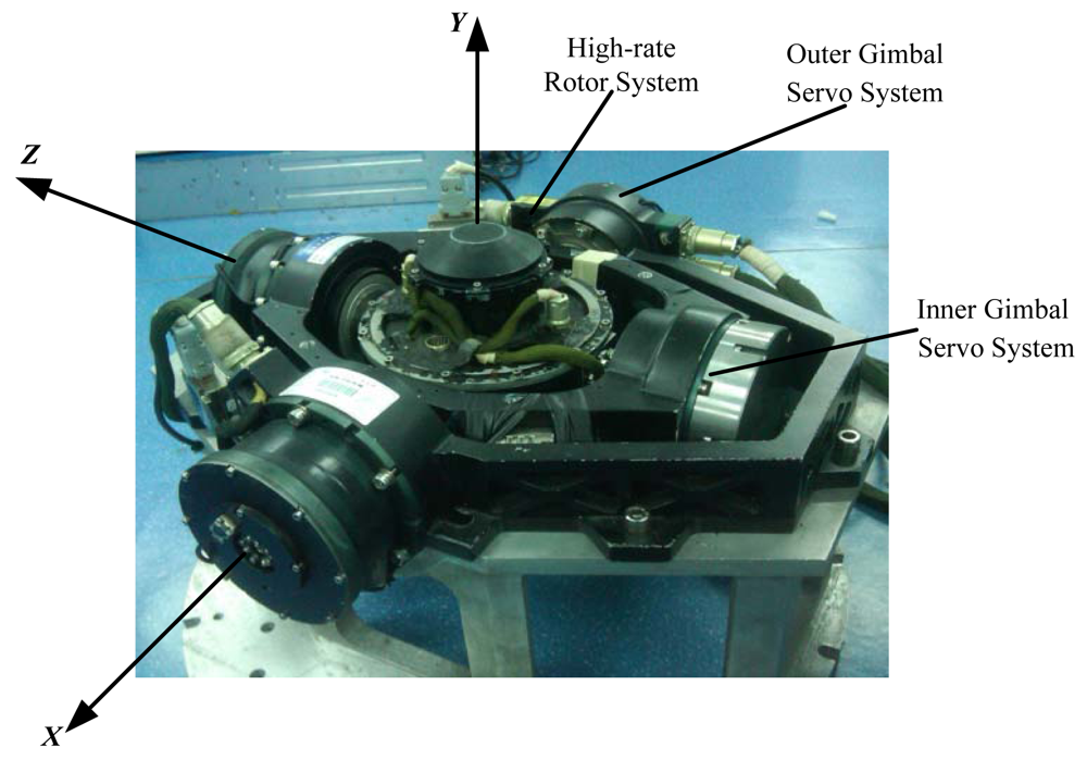
The MSDGCMG consists of inner and outer gimbal servo systems as well as a high-rate rotor system. The high-rate rotor is mounted in the stator housing and provides a constant angular momentum. With a specific rotation of inner and outer gimbal, the vector direction of the rotor angular momentum is changed to produce the desired gyroscope torques to meet the requirements of the attitude control. The main parameters of the MSDGCMG used in this paper are:
<list list-type="order">
<list-item>
<p>Angular momentum: ≥15 Nms.</p></list-item>
<list-item>
<p>Maximum output torque: ≥10 Nm.</p></list-item>
<list-item>
<p>Nominal rotor speed: 30,000 r/min.</p></list-item>
<list-item>
<p>Gimbal angle range: 0°∼360°.</p></list-item></list></p>
<p>Furthermore, the circuit box of MSDGCMG is used to control the inner and outer gimbal servo systems as well as the high-rate rotor system. Assume the inner gimbal axis, outer gimbal axis and rotor axis are perpendicular to each other at the initial time, then the MSDGCMG coordinate system is defined as in <xref ref-type="fig" rid="f1-sensors-12-09129">Figure 1</xref>, outer gimbal axis as <italic>X</italic> axis, inner gimbal axis as <italic>Z</italic> axis, and <italic>Y</italic> axis in agreement with the Right-handed Rule. When the rotor angular momentum revolves about the positive half of the <italic>Z</italic> axis, the inner gimbal angle changes <italic>α</italic>. When the rotor angular momentum revolves about the positive half of the <italic>X</italic> axis, the outer gimbal angle changes by −<italic>β</italic>.</p></sec>
<sec>
<label>4.2.</label>
<title>MSDGCMG Torque Equation</title>
<p>In this paper, MSDGCMG is put on the single axis air bearing table. At the initial time, the <italic>Y</italic> axis of the MSDGCMG coordinate system is parallel to the rotation (pitch) axis of the air bearing table, whereas the inner gimbal axis (<italic>Z</italic> axis) and the outer gimbal axis (<italic>X</italic> axis) are perpendicular to the pitch axis. Consequently, the installation matrix of MSDGCMG is a 3 × 3 identity matrix. According to the definition of the MSDGCMG coordinate system and the installation matrix, the CMG angular momentum vector is represented in the matrix form as:
<disp-formula id="FD14">
<label>(14)</label>
<mml:math id="mm14" display="block">
<mml:semantics id="sm14">
<mml:mrow>
<mml:msub>
<mml:mi>h</mml:mi>
<mml:mi>g</mml:mi></mml:msub>
<mml:mo>=</mml:mo>
<mml:msub>
<mml:mi>h</mml:mi>
<mml:mn>0</mml:mn></mml:msub>
<mml:mspace width="0.2em"/>
<mml:mrow>
<mml:mo>[</mml:mo>
<mml:mrow>
<mml:mtable>
<mml:mtr>
<mml:mtd>
<mml:mrow>
<mml:mo>−</mml:mo>
<mml:mo>sin</mml:mo>
<mml:mi>α</mml:mi></mml:mrow></mml:mtd></mml:mtr>
<mml:mtr>
<mml:mtd>
<mml:mrow>
<mml:mo>cos</mml:mo>
<mml:mi>α</mml:mi>
<mml:mo>cos</mml:mo>
<mml:mi>β</mml:mi></mml:mrow></mml:mtd></mml:mtr>
<mml:mtr>
<mml:mtd>
<mml:mrow>
<mml:mo>−</mml:mo>
<mml:mo>cos</mml:mo>
<mml:mi>α</mml:mi>
<mml:mo>sin</mml:mo>
<mml:mi>β</mml:mi></mml:mrow></mml:mtd></mml:mtr></mml:mtable></mml:mrow>
<mml:mo>]</mml:mo></mml:mrow></mml:mrow></mml:semantics></mml:math></disp-formula>where <italic>h</italic><sub>0</sub> is the angular momentum magnitude of the individual MSDGCMG, <italic>α</italic> and <italic>β</italic> are the inner and outer gimbal angle, respectively.</p>
<p>Therefore, the MSDGCMG output torque vector <italic>ḣ<sub>g</sub></italic> is derived as:
<disp-formula id="FD15">
<label>(15)</label>
<mml:math id="mm15" display="block">
<mml:semantics id="sm15">
<mml:mrow>
<mml:msub>
<mml:mover accent="true">
<mml:mi>h</mml:mi>
<mml:mo>˙</mml:mo></mml:mover>
<mml:mi>g</mml:mi></mml:msub>
<mml:mo>=</mml:mo>
<mml:msub>
<mml:mi>h</mml:mi>
<mml:mn>0</mml:mn></mml:msub>
<mml:mo>⋅</mml:mo>
<mml:mi>C</mml:mi>
<mml:mo>⋅</mml:mo>
<mml:mover accent="true">
<mml:mi>δ</mml:mi>
<mml:mo>˙</mml:mo></mml:mover></mml:mrow></mml:semantics></mml:math></disp-formula>where <italic>δ̇</italic> = [<italic>α̇ β̇</italic>]<italic><sup>T</sup></italic> is the gimbal angle rate, <italic>C</italic> is the Jacobian matrix:
<disp-formula id="FD16">
<label>(16)</label>
<mml:math id="mm16" display="block">
<mml:semantics id="sm16">
<mml:mrow>
<mml:mi>C</mml:mi>
<mml:mo>=</mml:mo>
<mml:mrow>
<mml:mo>[</mml:mo>
<mml:mrow>
<mml:mtable>
<mml:mtr>
<mml:mtd>
<mml:mrow>
<mml:mo>−</mml:mo>
<mml:mo>cos</mml:mo>
<mml:mi>α</mml:mi></mml:mrow></mml:mtd>
<mml:mtd>
<mml:mn>0</mml:mn></mml:mtd></mml:mtr>
<mml:mtr>
<mml:mtd>
<mml:mrow>
<mml:mo>−</mml:mo>
<mml:mo>sin</mml:mo>
<mml:mi>α</mml:mi>
<mml:mo>cos</mml:mo>
<mml:mi>β</mml:mi></mml:mrow></mml:mtd>
<mml:mtd>
<mml:mrow>
<mml:mo>−</mml:mo>
<mml:mo>cos</mml:mo>
<mml:mi>α</mml:mi>
<mml:mo>sin</mml:mo>
<mml:mi>β</mml:mi></mml:mrow></mml:mtd></mml:mtr>
<mml:mtr>
<mml:mtd>
<mml:mrow>
<mml:mo>sin</mml:mo>
<mml:mi>α</mml:mi>
<mml:mo>sin</mml:mo>
<mml:mi>β</mml:mi></mml:mrow></mml:mtd>
<mml:mtd>
<mml:mrow>
<mml:mo>−</mml:mo>
<mml:mo>cos</mml:mo>
<mml:mi>α</mml:mi>
<mml:mo>cos</mml:mo>
<mml:mi>β</mml:mi></mml:mrow></mml:mtd></mml:mtr></mml:mtable></mml:mrow>
<mml:mo>]</mml:mo></mml:mrow></mml:mrow></mml:semantics></mml:math></disp-formula></p>
<p>It is clearly seen from the above equation that, the Jacobian matrix is a nonlinear function of the gimbal angles <italic>α</italic> and <italic>β</italic>.</p></sec>
<sec>
<label>4.3.</label>
<title>MSDGCMG Steering Law</title>
<p>For the attitude control of the single axis air bearing table, particular attention should be paid to the MSDGCMG output torque along the pitch axis. Therefore <italic>A</italic> is written by extracting the second row of Jacobian matrix <italic>C</italic>:
<disp-formula id="FD17">
<label>(17)</label>
<mml:math id="mm17" display="block">
<mml:semantics id="sm17">
<mml:mrow>
<mml:mi>A</mml:mi>
<mml:mo>=</mml:mo>
<mml:mrow>
<mml:mo stretchy="false">[</mml:mo>
<mml:mrow>
<mml:mtable>
<mml:mtr>
<mml:mtd>
<mml:mrow>
<mml:mo>−</mml:mo>
<mml:mo>sin</mml:mo>
<mml:mi>α</mml:mi>
<mml:mo>cos</mml:mo>
<mml:mi>β</mml:mi></mml:mrow></mml:mtd>
<mml:mtd>
<mml:mrow>
<mml:mo>−</mml:mo>
<mml:mo>cos</mml:mo>
<mml:mi>α</mml:mi>
<mml:mo>sin</mml:mo>
<mml:mi>β</mml:mi></mml:mrow></mml:mtd></mml:mtr></mml:mtable></mml:mrow>
<mml:mo stretchy="false">]</mml:mo></mml:mrow></mml:mrow></mml:semantics></mml:math></disp-formula></p>
<p>The command gimbal rate <italic>δ̇</italic>, referred to as the pseudoinverse steering law, is then obtained as:
<disp-formula id="FD18">
<label>(18)</label>
<mml:math id="mm18" display="block">
<mml:semantics id="sm18">
<mml:mrow>
<mml:mover accent="true">
<mml:mi>δ</mml:mi>
<mml:mo>˙</mml:mo></mml:mover>
<mml:mo>=</mml:mo>
<mml:mo>−</mml:mo>
<mml:msup>
<mml:mi>A</mml:mi>
<mml:mo>+</mml:mo></mml:msup>
<mml:mi>u</mml:mi>
<mml:mo>/</mml:mo>
<mml:msub>
<mml:mi>h</mml:mi>
<mml:mn>0</mml:mn></mml:msub>
<mml:mspace width="0.5em"/>
<mml:mtext>where</mml:mtext>
<mml:mspace width="0.5em"/>
<mml:msup>
<mml:mi>A</mml:mi>
<mml:mo>+</mml:mo></mml:msup>
<mml:mo>=</mml:mo>
<mml:msup>
<mml:mi>A</mml:mi>
<mml:mi>T</mml:mi></mml:msup>
<mml:msup>
<mml:mrow>
<mml:mo stretchy="false">(</mml:mo>
<mml:mi>A</mml:mi>
<mml:msup>
<mml:mi>A</mml:mi>
<mml:mi>T</mml:mi></mml:msup>
<mml:mo stretchy="false">)</mml:mo></mml:mrow>
<mml:mrow>
<mml:mo>−</mml:mo>
<mml:mn>1</mml:mn></mml:mrow></mml:msup></mml:mrow></mml:semantics></mml:math></disp-formula>where <italic>u</italic> denotes the command control torque derived by the attitude control law in the preceding section.</p>
<p>For the reason that the high-rate magnetically suspended rotor of the MSDGCMG is actually active-control elastic supporting with certain stiffness and damping, the gimbal movement will disturb the magnetically suspended rotor. For simplicity, the phenomena caused by the gimbal movement are called the moving-gimbal effects. On the other hand, the response bandwidth of the CMG gimbal is constrained by the output torque ability of gimbal motor, thus the gimbal servo systems are unable to respond to the large gimbal angle acceleration. Consequently, the limit of the gimbal angle velocity and the acceleration should be given full consideration, to make sure that the high-speed rotor would work steadily around the operating point.</p>
<p>Furthermore, the singularity problem is inherent in the CMG. When the MSDGCMG is trapped in the singular state, the gimbal of the MSDGCMG will vibrate seriously so as to influence the stability of the MSDGCMG. Therefore, the maximum gimbal angle acceleration <italic>δ̈</italic><sub>max</sub> is determined on the basis of the singularity measurement:
<disp-formula id="FD19">
<label>(19)</label>
<mml:math id="mm19" display="block">
<mml:semantics id="sm19">
<mml:mrow>
<mml:msub>
<mml:mover accent="true">
<mml:mi>δ</mml:mi>
<mml:mo>¨</mml:mo></mml:mover>
<mml:mrow>
<mml:mo>max</mml:mo></mml:mrow></mml:msub>
<mml:mo>=</mml:mo>
<mml:mrow>
<mml:mo>{</mml:mo>
<mml:mrow>
<mml:mtable columnalign="left">
<mml:mtr columnalign="left">
<mml:mtd columnalign="left">
<mml:mrow>
<mml:msub>
<mml:mover accent="true">
<mml:mi>δ</mml:mi>
<mml:mo>¨</mml:mo></mml:mover>
<mml:mrow>
<mml:mo>max</mml:mo>
<mml:mn>1</mml:mn></mml:mrow></mml:msub></mml:mrow></mml:mtd>
<mml:mtd columnalign="left">
<mml:mrow>
<mml:mi>i</mml:mi>
<mml:mi>f</mml:mi></mml:mrow></mml:mtd>
<mml:mtd columnalign="left">
<mml:mrow>
<mml:mn>0</mml:mn>
<mml:mo>&lt;</mml:mo>
<mml:mi>D</mml:mi>
<mml:mo>&lt;</mml:mo>
<mml:mi>d</mml:mi></mml:mrow></mml:mtd></mml:mtr>
<mml:mtr columnalign="left">
<mml:mtd columnalign="left">
<mml:mrow>
<mml:msub>
<mml:mover accent="true">
<mml:mi>δ</mml:mi>
<mml:mo>¨</mml:mo></mml:mover>
<mml:mrow>
<mml:mo>max</mml:mo>
<mml:mn>2</mml:mn></mml:mrow></mml:msub></mml:mrow></mml:mtd>
<mml:mtd columnalign="left">
<mml:mrow>
<mml:mi>i</mml:mi>
<mml:mi>f</mml:mi></mml:mrow></mml:mtd>
<mml:mtd columnalign="left">
<mml:mrow>
<mml:mi>D</mml:mi>
<mml:mo>≥</mml:mo>
<mml:mi>d</mml:mi></mml:mrow></mml:mtd></mml:mtr></mml:mtable></mml:mrow></mml:mrow></mml:mrow></mml:semantics></mml:math></disp-formula>where <italic>D</italic> = det(<italic>AA<sup>T</sup></italic>) is the singularity measurement, <italic>d</italic> is the piecewise point.</p>
<p>In the experiment, the maximum limit of the gimbal angle acceleration is firstly taken into consideration. The inner and outer gimbal angle acceleration <italic>δ̈<sub>k</sub></italic> at moment <italic>k</italic> is calculated as:
<disp-formula id="FD20">
<label>(20)</label>
<mml:math id="mm20" display="block">
<mml:semantics id="sm20">
<mml:mrow>
<mml:msub>
<mml:mover accent="true">
<mml:mi>δ</mml:mi>
<mml:mo>¨</mml:mo></mml:mover>
<mml:mi>k</mml:mi></mml:msub>
<mml:mo>=</mml:mo>
<mml:mo stretchy="false">(</mml:mo>
<mml:msub>
<mml:mover accent="true">
<mml:mi>δ</mml:mi>
<mml:mo>˙</mml:mo></mml:mover>
<mml:mi>k</mml:mi></mml:msub>
<mml:mo>−</mml:mo>
<mml:msub>
<mml:mover accent="true">
<mml:mi>δ</mml:mi>
<mml:mo>˙</mml:mo></mml:mover>
<mml:mrow>
<mml:mi>k</mml:mi>
<mml:mo>−</mml:mo>
<mml:mn>1</mml:mn></mml:mrow></mml:msub>
<mml:mo stretchy="false">)</mml:mo>
<mml:mo>/</mml:mo>
<mml:msub>
<mml:mi>T</mml:mi>
<mml:mi>s</mml:mi></mml:msub></mml:mrow></mml:semantics></mml:math></disp-formula>where <italic>δ̇<sub>k</sub></italic> and <italic>δ̇<sub>k</sub></italic><sub>−1</sub> are the command gimbal angle rates at moment <italic>k</italic> and <italic>k</italic> − 1, respectively. <italic>T</italic><sub>s</sub> denotes the control cycle. Then the gimbal angle acceleration is constrained as follows:
<disp-formula id="FD21">
<label>(21)</label>
<mml:math id="mm21" display="block">
<mml:semantics id="sm21">
<mml:mrow>
<mml:msub>
<mml:mover accent="true">
<mml:mi>δ</mml:mi>
<mml:mo>∼</mml:mo></mml:mover>
<mml:mo>¨</mml:mo></mml:mover>
<mml:mi>k</mml:mi></mml:msub>
<mml:mo>=</mml:mo>
<mml:mrow>
<mml:mo>{</mml:mo>
<mml:mrow>
<mml:mtable>
<mml:mtr>
<mml:mtd>
<mml:mrow>
<mml:msub>
<mml:mover accent="true">
<mml:mi>δ</mml:mi>
<mml:mo>¨</mml:mo></mml:mover>
<mml:mi>k</mml:mi></mml:msub></mml:mrow></mml:mtd>
<mml:mtd>
<mml:mrow>
<mml:mtable>
<mml:mtr>
<mml:mtd>
<mml:mrow>
<mml:mi>i</mml:mi>
<mml:mi>f</mml:mi></mml:mrow></mml:mtd>
<mml:mtd>
<mml:mrow>
<mml:msub>
<mml:mrow>
<mml:mrow>
<mml:mo>‖</mml:mo>
<mml:mrow>
<mml:msub>
<mml:mover accent="true">
<mml:mi>δ</mml:mi>
<mml:mo>¨</mml:mo></mml:mover>
<mml:mi>k</mml:mi></mml:msub></mml:mrow>
<mml:mo>‖</mml:mo></mml:mrow></mml:mrow>
<mml:mo>∞</mml:mo></mml:msub>
<mml:mo>&lt;</mml:mo>
<mml:msub>
<mml:mover accent="true">
<mml:mi>δ</mml:mi>
<mml:mo>¨</mml:mo></mml:mover>
<mml:mrow>
<mml:mo>max</mml:mo></mml:mrow></mml:msub></mml:mrow></mml:mtd></mml:mtr></mml:mtable></mml:mrow></mml:mtd></mml:mtr>
<mml:mtr>
<mml:mtd>
<mml:mrow>
<mml:msub>
<mml:mover accent="true">
<mml:mi>δ</mml:mi>
<mml:mo>¨</mml:mo></mml:mover>
<mml:mi>k</mml:mi></mml:msub>
<mml:mfrac>
<mml:mrow>
<mml:msub>
<mml:mover accent="true">
<mml:mi>δ</mml:mi>
<mml:mo>¨</mml:mo></mml:mover>
<mml:mrow>
<mml:mo>max</mml:mo></mml:mrow></mml:msub></mml:mrow>
<mml:mrow>
<mml:msub>
<mml:mrow>
<mml:mrow>
<mml:mo>‖</mml:mo>
<mml:mrow>
<mml:msub>
<mml:mover accent="true">
<mml:mi>δ</mml:mi>
<mml:mo>¨</mml:mo></mml:mover>
<mml:mi>k</mml:mi></mml:msub></mml:mrow>
<mml:mo>‖</mml:mo></mml:mrow></mml:mrow>
<mml:mo>∞</mml:mo></mml:msub></mml:mrow></mml:mfrac></mml:mrow></mml:mtd>
<mml:mtd>
<mml:mrow>
<mml:mtable>
<mml:mtr>
<mml:mtd>
<mml:mrow>
<mml:mi>i</mml:mi>
<mml:mi>f</mml:mi></mml:mrow></mml:mtd>
<mml:mtd>
<mml:mrow>
<mml:msub>
<mml:mrow>
<mml:mrow>
<mml:mo>‖</mml:mo>
<mml:mrow>
<mml:msub>
<mml:mover accent="true">
<mml:mi>δ</mml:mi>
<mml:mo>¨</mml:mo></mml:mover>
<mml:mi>k</mml:mi></mml:msub></mml:mrow>
<mml:mo>‖</mml:mo></mml:mrow></mml:mrow>
<mml:mo>∞</mml:mo></mml:msub>
<mml:mo>≥</mml:mo>
<mml:msub>
<mml:mover accent="true">
<mml:mi>δ</mml:mi>
<mml:mo>¨</mml:mo></mml:mover>
<mml:mrow>
<mml:mo>max</mml:mo></mml:mrow></mml:msub></mml:mrow></mml:mtd></mml:mtr></mml:mtable></mml:mrow></mml:mtd></mml:mtr></mml:mtable></mml:mrow></mml:mrow></mml:mrow></mml:semantics></mml:math></disp-formula>where ‖•‖<sub>∞</sub> is the infinite norm of the vector, and then the command gimbal rate at the moment <italic>k</italic> is modified as:
<disp-formula id="FD22">
<label>(22)</label>
<mml:math id="mm22" display="block">
<mml:semantics id="sm22">
<mml:mrow>
<mml:msub>
<mml:mover accent="true">
<mml:mi>δ</mml:mi>
<mml:mo>˙</mml:mo></mml:mover>
<mml:mi>k</mml:mi></mml:msub>
<mml:mo>=</mml:mo>
<mml:msub>
<mml:mover accent="true">
<mml:mi>δ</mml:mi>
<mml:mo>˙</mml:mo></mml:mover>
<mml:mrow>
<mml:mi>k</mml:mi>
<mml:mo>−</mml:mo>
<mml:mn>1</mml:mn></mml:mrow></mml:msub>
<mml:mo>+</mml:mo>
<mml:msub>
<mml:mover accent="true">
<mml:mi>δ</mml:mi>
<mml:mo>∼</mml:mo></mml:mover>
<mml:mo>¨</mml:mo></mml:mover>
<mml:mi>k</mml:mi></mml:msub>
<mml:mo>⋅</mml:mo>
<mml:msub>
<mml:mi>T</mml:mi>
<mml:mi>s</mml:mi></mml:msub></mml:mrow></mml:semantics></mml:math></disp-formula></p>
<p>Finally, the gimbal angle velocity is calculated as follows:
<disp-formula id="FD23">
<label>(23)</label>
<mml:math id="mm23" display="block">
<mml:semantics id="sm23">
<mml:mrow>
<mml:msub>
<mml:mover accent="true">
<mml:mi>δ</mml:mi>
<mml:mo>∼</mml:mo></mml:mover>
<mml:mo>˙</mml:mo></mml:mover>
<mml:mi>k</mml:mi></mml:msub>
<mml:mo>=</mml:mo>
<mml:mrow>
<mml:mo>{</mml:mo>
<mml:mrow>
<mml:mtable>
<mml:mtr>
<mml:mtd>
<mml:mrow>
<mml:msub>
<mml:mover accent="true">
<mml:mi>δ</mml:mi>
<mml:mo>˙</mml:mo></mml:mover>
<mml:mi>k</mml:mi></mml:msub></mml:mrow></mml:mtd>
<mml:mtd>
<mml:mrow>
<mml:mtable>
<mml:mtr>
<mml:mtd>
<mml:mrow>
<mml:mi>i</mml:mi>
<mml:mi>f</mml:mi></mml:mrow></mml:mtd>
<mml:mtd>
<mml:mrow>
<mml:msub>
<mml:mrow>
<mml:mrow>
<mml:mo>‖</mml:mo>
<mml:mrow>
<mml:msub>
<mml:mover accent="true">
<mml:mi>δ</mml:mi>
<mml:mo>˙</mml:mo></mml:mover>
<mml:mi>k</mml:mi></mml:msub></mml:mrow>
<mml:mo>‖</mml:mo></mml:mrow></mml:mrow>
<mml:mo>∞</mml:mo></mml:msub>
<mml:mo>&lt;</mml:mo>
<mml:msub>
<mml:mover accent="true">
<mml:mi>δ</mml:mi>
<mml:mo>˙</mml:mo></mml:mover>
<mml:mrow>
<mml:mo>max</mml:mo></mml:mrow></mml:msub></mml:mrow></mml:mtd></mml:mtr></mml:mtable></mml:mrow></mml:mtd></mml:mtr>
<mml:mtr>
<mml:mtd>
<mml:mrow>
<mml:msub>
<mml:mover accent="true">
<mml:mi>δ</mml:mi>
<mml:mo>˙</mml:mo></mml:mover>
<mml:mi>k</mml:mi></mml:msub>
<mml:mfrac>
<mml:mrow>
<mml:msub>
<mml:mover accent="true">
<mml:mi>δ</mml:mi>
<mml:mo>˙</mml:mo></mml:mover>
<mml:mrow>
<mml:mo>max</mml:mo></mml:mrow></mml:msub></mml:mrow>
<mml:mrow>
<mml:msub>
<mml:mrow>
<mml:mrow>
<mml:mo>‖</mml:mo>
<mml:mrow>
<mml:msub>
<mml:mover accent="true">
<mml:mi>δ</mml:mi>
<mml:mo>˙</mml:mo></mml:mover>
<mml:mi>k</mml:mi></mml:msub></mml:mrow>
<mml:mo>‖</mml:mo></mml:mrow></mml:mrow>
<mml:mo>∞</mml:mo></mml:msub></mml:mrow></mml:mfrac></mml:mrow></mml:mtd>
<mml:mtd>
<mml:mrow>
<mml:mtable>
<mml:mtr>
<mml:mtd>
<mml:mrow>
<mml:mi>i</mml:mi>
<mml:mi>f</mml:mi></mml:mrow></mml:mtd>
<mml:mtd>
<mml:mrow>
<mml:msub>
<mml:mrow>
<mml:mrow>
<mml:mo>‖</mml:mo>
<mml:mrow>
<mml:msub>
<mml:mover accent="true">
<mml:mi>δ</mml:mi>
<mml:mo>˙</mml:mo></mml:mover>
<mml:mi>k</mml:mi></mml:msub></mml:mrow>
<mml:mo>‖</mml:mo></mml:mrow></mml:mrow>
<mml:mo>∞</mml:mo></mml:msub>
<mml:mo>≥</mml:mo>
<mml:msub>
<mml:mover accent="true">
<mml:mi>δ</mml:mi>
<mml:mo>˙</mml:mo></mml:mover>
<mml:mrow>
<mml:mo>max</mml:mo></mml:mrow></mml:msub></mml:mrow></mml:mtd></mml:mtr></mml:mtable></mml:mrow></mml:mtd></mml:mtr></mml:mtable></mml:mrow></mml:mrow></mml:mrow></mml:semantics></mml:math></disp-formula>where <italic>δ̇</italic><sub>max</sub> denotes the allowed maximum gimbal angle rate. Then the command gimbal angle rate 
<inline-graphic xlink:href="sensors-12-09129i1.gif"/><italic><sub>k</sub></italic> is derived from <xref rid="FD23" ref-type="disp-formula">Equation (23)</xref> taking account of the limit of the gimbal angle rate and acceleration.</p>
<p>Note that the maximum limit of the gimbal angle rate and the acceleration defined as above has the same direction as that of themselves before maximum limit. That is, the MSDGCMG output torque is kept the same direction as the command control torque, but the magnitude of the actual torque is reduced.</p></sec></sec>
<sec sec-type="methods">
<label>5.</label>
<title>Design of the Semi-Physical Simulation Platform for MSDGCMG Performance Testing</title>
<p>The design of semi-physical simulation platform for MSDGCMG performance testing is introduced in this section. The single axis air bearing table is used to simulate the pitch axis of the satellite. The MSDGCMG is mounted on the air bearing table and is used as an attitude actuator to realize rapid maneuvers and quick stability of the air bearing table.</p>
<p>
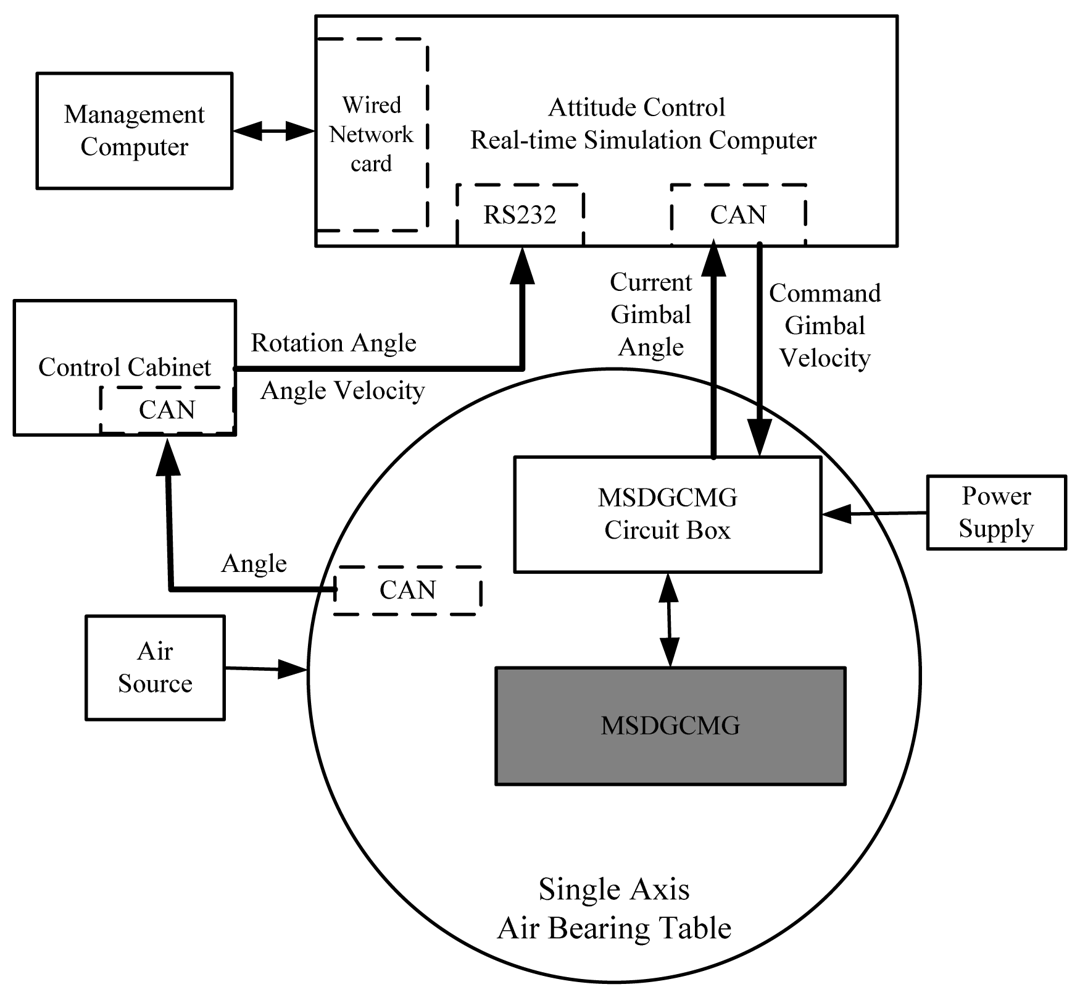
The hardware used in the semi-physical simulation platform is mainly composed of the MSDGCMG, the corresponding circuit box, single axis air bearing table, control cabinet of the air bearing table, attitude control real-time simulation computer, simulation management computer, power module, and so on. The hardware layout frame of the semi-physical simulation system is depicted in <xref ref-type="fig" rid="f2-sensors-12-09129">Figure 2</xref>.</p>
<p>The signal flow of the hardware is described as follows: the rotation angle of the air bearing table is measured by the photo-electric encoder fixed to the single axis air bearing table, and then is delivered to the control cabinet through CAN bus. The control cabinet collects the rotation angle information, derives the angle velocity through differential filtering of the rotation angle, and then delivers the rotation angle and angle velocity to the real-time simulation computer through the RS232 serial port. According to the error-angle between the current rotation angle and the command angle, the command torque is generated through the parameter segment control algorithm. In light of the command torque and the current MSDGCMG gimbal angle, the command gimbal rate is computed and is sent to the MSDGCMG circuit box through the CAN bus. The circuit box receives the command and then controls the gimbal servo system to rotate the gimbals. Because of the change of the direction of CMG angle momentum, the desired control torque of the MSDGCMG is finally exerted on the air bearing table.</p>
<p>In this experiment, the single axis air bearing table is the supporting platform of the attitude control semi-physical simulation system and the main parameters are described as:
<list list-type="order">
<list-item>
<p>Loading capacity: &gt;200 Kg.</p></list-item>
<list-item>
<p>Friction torque: &lt;5 × 10<sup>−4</sup> Nm.</p></list-item>
<list-item>
<p>Rotation angle range: ±360°.</p></list-item>
<list-item>
<p>Rotation angle measurement accuracy: ±10<sup>−3</sup>°.</p></list-item>
<list-item>
<p>Rotation angle minimum resolution: 2.5 × 10<sup>−4</sup>°.</p></list-item></list></p>
<p>The attitude control real-time simulation system is a hardware-in-loop semi-physical simulation, which supports the Matlab/Simulink graphical module design, seamless connection with C coder, and automatic production of code. The hardware of this system is mainly composed of the simulation management computer (host computer), real-time simulation computer (target computer) and signal processing box. The main function of host computer here is to manage the real-time target computer. The host computer is based on the Windows platform, and Matlab/Simulink is applied for building the simulation model. The target computer adopts the Vxworks real-time operating system to guarantee the reliability of the semi-physical simulation. The communication between the host computer and the target computer is by means of Ethernet networks. What's more, the major role of the signal process box is to provide the signal processing and connection to the I/O interface, and to ensure the data communication between the semi-physical simulation platform and the hardware equipment.</p></sec>
<sec sec-type="methods|results">
<label>6.</label>
<title>Experimental Results and Analysis</title>
<p>
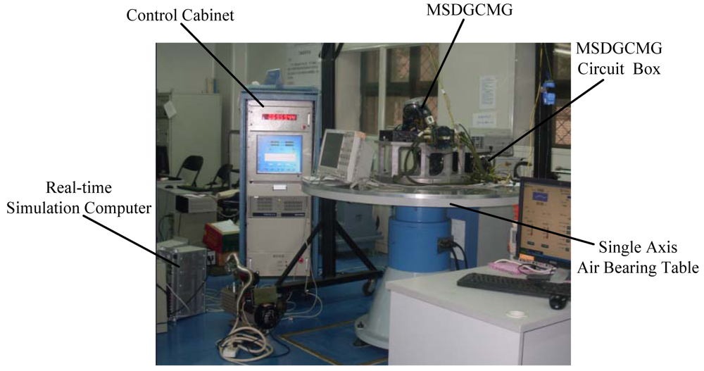
Having designed the attitude control law, the MSDGCMG steering law as well as the semi-physical simulation platform, experiments are conducted in this section to validate the performance of the MSDGCMG. The following mainly includes the measurement of the moment of inertia, the measurement of the disturbance torques, experimental results and analysis. The experimental scenario is given in <xref ref-type="fig" rid="f3-sensors-12-09129">Figure 3</xref>.</p>
<sec>
<label>6.1.</label>
<title>Measurement of the Moment of Inertia</title>
<p>The measurement of the air bearing table moment of inertia is important in the initial stage of the semi-physical simulation. Here the twisting vibration approach [<xref ref-type="bibr" rid="b18-sensors-12-09129">18</xref>] is applied for measuring the moment of inertia. This method has the advantages of simple design, easy operation, as well as not needing any knowledge of the air bearing table mass. Only the spring resonance device is needed in our experiment.</p>
<p>During the measurement of the moment of inertia, it should be ensured that the vibration amplitude of the air bearing table is small to satisfy the condition of micro-amplitude. However, the equivalent torsional stiffness is difficult to measure, and the change of torsional stiffness resulting from the reinstallation brings about large error in the moment of inertia. In order to obtain the moment of inertia <italic>J</italic> precisely, two standard cylinder balance masses are symmetrically placed on the air bearing table, and then the air bearing table moment of inertia is given as:
<disp-formula id="FD24">
<label>(24)</label>
<mml:math id="mm24" display="block">
<mml:semantics id="sm24">
<mml:mrow>
<mml:mi>J</mml:mi>
<mml:mo>=</mml:mo>
<mml:mfrac>
<mml:mrow>
<mml:msubsup>
<mml:mi>f</mml:mi>
<mml:mn>2</mml:mn>
<mml:mn>2</mml:mn></mml:msubsup></mml:mrow>
<mml:mrow>
<mml:msubsup>
<mml:mi>f</mml:mi>
<mml:mn>1</mml:mn>
<mml:mn>2</mml:mn></mml:msubsup>
<mml:mo>−</mml:mo>
<mml:msubsup>
<mml:mi>f</mml:mi>
<mml:mn>2</mml:mn>
<mml:mn>2</mml:mn></mml:msubsup></mml:mrow></mml:mfrac>
<mml:mo>⋅</mml:mo>
<mml:mi mathvariant="normal">Δ</mml:mi>
<mml:mi>J</mml:mi></mml:mrow></mml:semantics></mml:math></disp-formula>where <italic>f</italic><sub>1</sub> denotes the system vibration frequency without the balance mass, <italic>f</italic><sub>2</sub> denotes the system vibration frequency when the air bearing table is installed with the balance masses, Δ<italic>J</italic> is the increased moment of inertia:
<disp-formula id="FD25">
<label>(25)</label>
<mml:math id="mm25" display="block">
<mml:semantics id="sm25">
<mml:mrow>
<mml:mi mathvariant="normal">Δ</mml:mi>
<mml:mi>J</mml:mi>
<mml:mo>=</mml:mo>
<mml:mn>2</mml:mn>
<mml:msub>
<mml:mi>m</mml:mi>
<mml:mn>0</mml:mn></mml:msub>
<mml:msup>
<mml:mi>L</mml:mi>
<mml:mn>2</mml:mn></mml:msup>
<mml:mo>+</mml:mo>
<mml:msub>
<mml:mi>m</mml:mi>
<mml:mn>0</mml:mn></mml:msub>
<mml:msup>
<mml:mi>r</mml:mi>
<mml:mn>2</mml:mn></mml:msup></mml:mrow></mml:semantics></mml:math></disp-formula>where <italic>m</italic><sub>0</sub> and <italic>r</italic> are the mass and the radius of the balance mass, respectively. <italic>L</italic> represents the distance from the rotating axis of the air bearing table to the centre of the balance mass.</p>
<p>Here the vibration period is calculated by counting the zero-crossing number of the air bearing table angle velocity within a specified time. Multiple measurements are carried out, and an average measurement value is used from ten attempts. The experimental data is shown in <xref ref-type="table" rid="t1-sensors-12-09129">Table 1</xref>:</p></sec>
<sec>
<label>6.2.</label>
<title>Measurement of the Disturbance Torques</title>
<p>In the experiment, the air bearing table is subjected to some external disturbance torques, such as gravity torque resulted from incomplete balancing, friction torque produced from air bearing, the resistance moment caused by communication cable and power supply cable, and so on. Taking account of the influence of the disturbance torques on the control accuracy and attitude stability, the disturbance torque <italic>T<sub>d</sub></italic> is calculated and the equation is given as follows [<xref ref-type="bibr" rid="b19-sensors-12-09129">19</xref>]:
<disp-formula id="FD26">
<label>(26)</label>
<mml:math id="mm26" display="block">
<mml:semantics id="sm26">
<mml:mrow>
<mml:msub>
<mml:mi>T</mml:mi>
<mml:mi>d</mml:mi></mml:msub>
<mml:mo>=</mml:mo>
<mml:mi>J</mml:mi>
<mml:mfrac>
<mml:mrow>
<mml:mi mathvariant="normal">Δ</mml:mi>
<mml:mi>ω</mml:mi></mml:mrow>
<mml:mrow>
<mml:mi mathvariant="normal">Δ</mml:mi>
<mml:mi>t</mml:mi></mml:mrow></mml:mfrac></mml:mrow></mml:semantics></mml:math></disp-formula>where Δ<italic>ω</italic> denotes the change of angle velocity during time Δ<italic>t</italic>.</p>
<p>Through multiple measurements, the average value of the disturbance torque is measured as 1.09 × 10<sup>−4</sup> Nm.</p></sec>
<sec>
<label>6.3.</label>
<title>Experimental Results and Analysis</title>
<p>In the experiment, the parameter segment attitude control law developed in this paper is now integrated to the MSDGCMG steering law. The parameters shown in the preceding sections are properly selected as in <xref ref-type="table" rid="t2-sensors-12-09129">Table 2</xref>.</p>
<p>
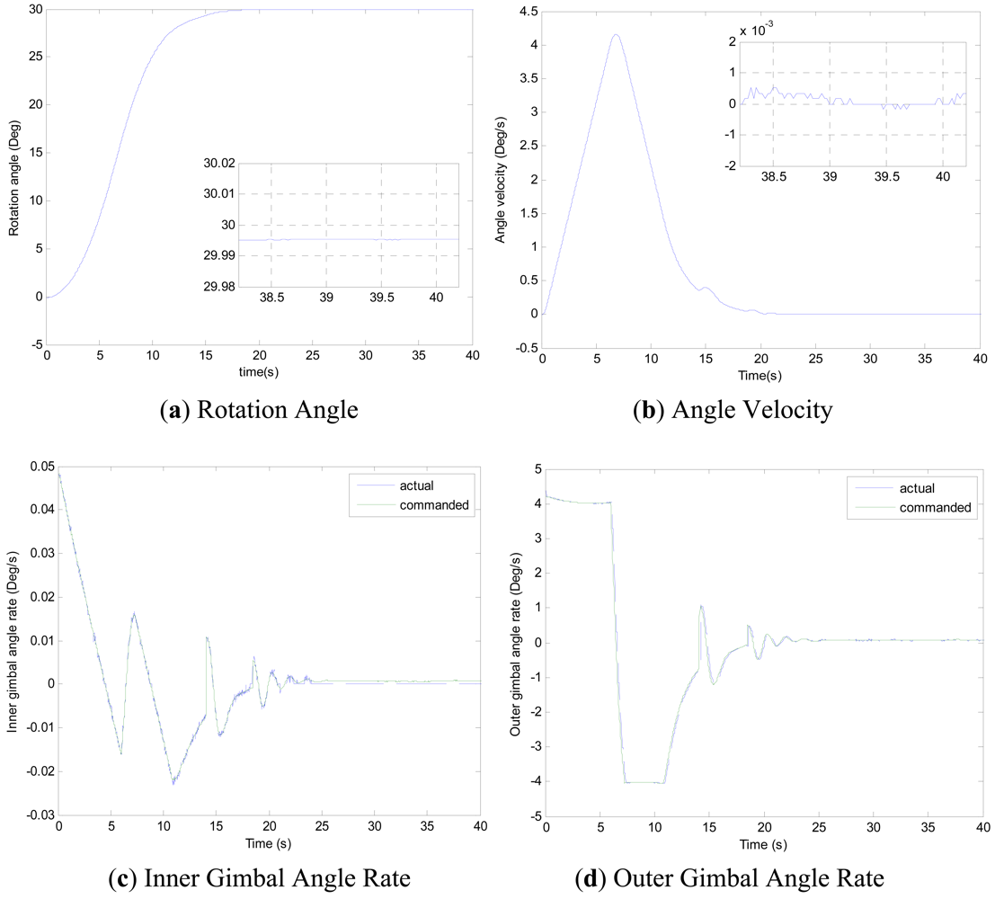
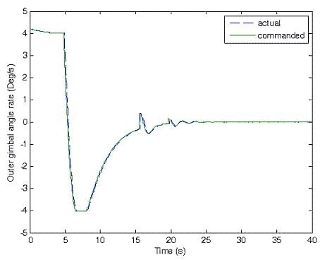
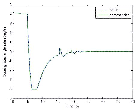
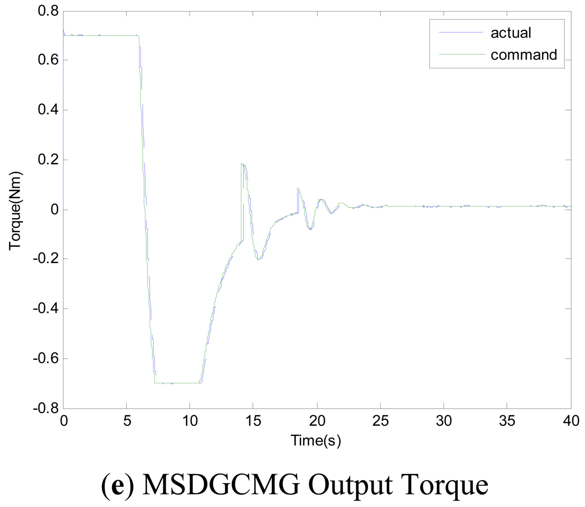
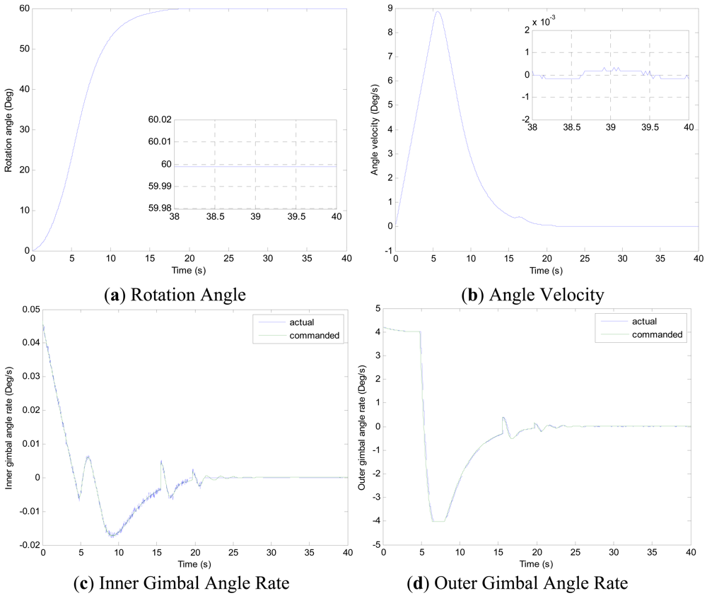
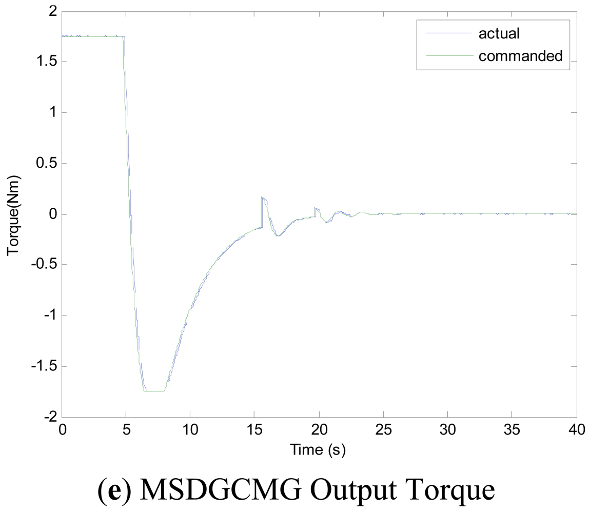
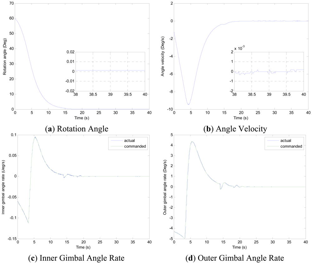
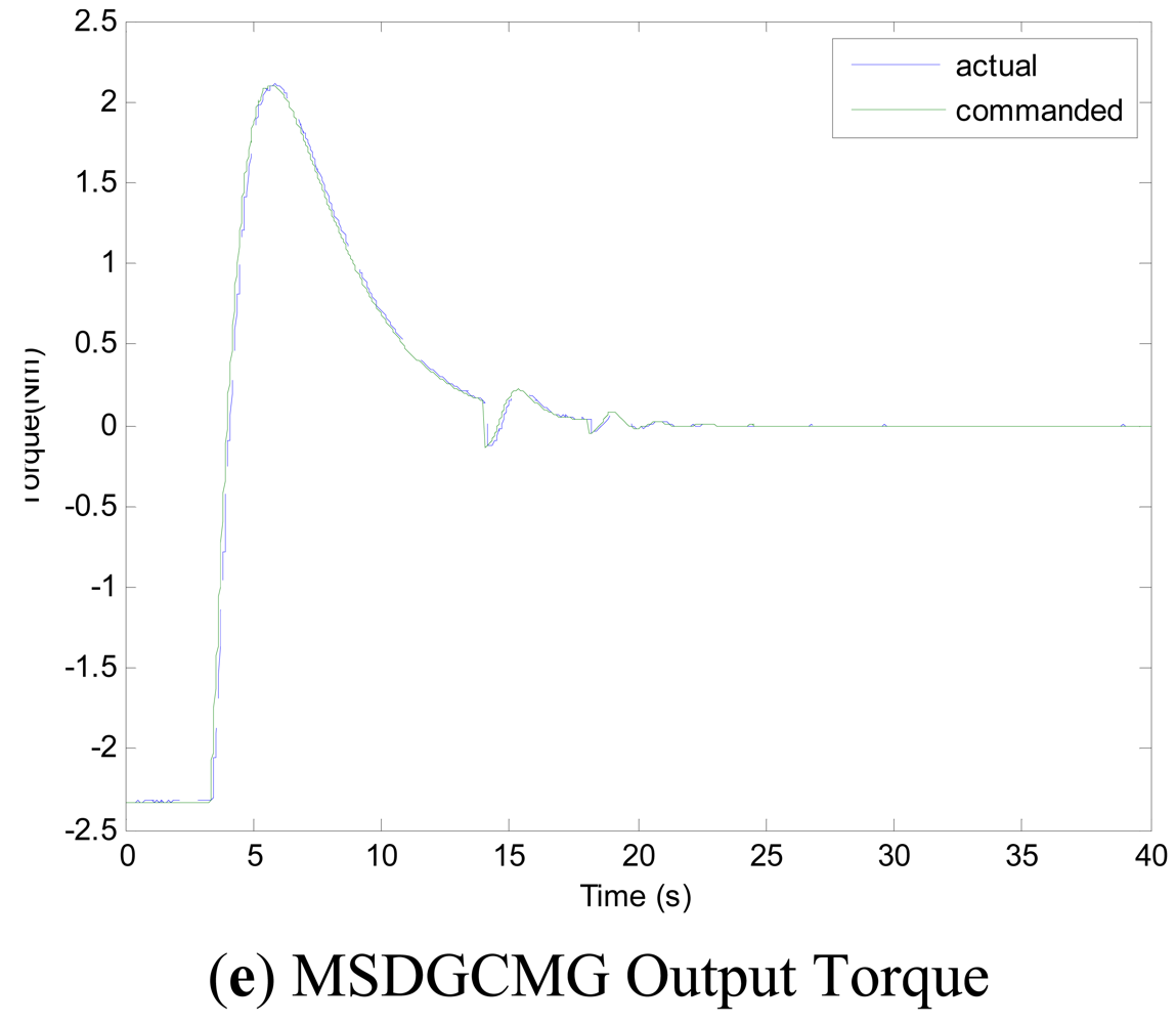
Experiments of the following three cases are carried out with different MSDGCMG rotor speed and different command rotation angles of the air bearing table. Case 1, as shown in <xref ref-type="fig" rid="f4-sensors-12-09129">Figure 4</xref>, is to realize a 30° attitude maneuver with 6,000 rpm rotor speed of the MSDGCMG. In this case, the initial air bearing table angle is 0°, and the command angle is set at 30°. Case 2, as shown in <xref ref-type="fig" rid="f5-sensors-12-09129">Figure 5</xref>, is to realize 60° attitude maneuver with 15,000 rpm rotor speed. In this case, the initial angle is 0°, and the command is 60°. Case 3, as shown in <xref ref-type="fig" rid="f6-sensors-12-09129">Figure 6</xref>, is to realize 60° attitude maneuver with 20,000 rpm rotor speed. In this case, the initial angle is 60°, and the command is 0°.</p>
<p>From the experimental results of the three cases, it is indicated that the larger the rotor speed (angular momentum of the MSDGCMG) is, the shorter the time required to realize the same angle maneuver is, meaning that the greater the maneuver ability is. It's easily known from the above figures that, the inner and outer gimbal angle rates follow the command perfectly, and that MSDGCMG output torque almost agrees with the command torque under the moving-base condition. Moreover, the attitude stability with the MSDGCMG as an actuator is superior to 10<sup>−3</sup>°/s, and there exists no transient overshoot during the process of the rapid maneuver and quick stability.</p>
<p>It is clearly seen from the <xref ref-type="table" rid="t3-sensors-12-09129">Table 3</xref> that, the MSDGCMG angle momentum determines the maneuver velocity, and that the maximum average maneuver ability is up to 3.57°/s. For the reason of the coupling between the air bearing table, MSDGCMG gimbal and high-rate rotor, the quicker the angle velocity of the air bearing table is, the more serious the influence on the high-rate magnetically suspended rotor becomes. In the experiment, for the reason of the high-precision magnetic bearing control, the MSDGCMG is able to overcome the influence that moving-base effects bring about, even when the maximum angle velocity reaches to 9.49°/s and the speed of high-rate rotor is 20,000 rpm.</p>
<p>In the future, advanced control algorithms [<xref ref-type="bibr" rid="b20-sensors-12-09129">20</xref>–<xref ref-type="bibr" rid="b22-sensors-12-09129">22</xref>] can be employed to further improve the control performance.</p></sec></sec>
<sec sec-type="conclusions">
<label>7.</label>
<title>Conclusions</title>
<p>In order to fully validate the performance of the MSDGCMG developed by Beihang University, experiments under the moving-base condition are carried out, with different MSDGCMG rotor speeds and different command rotation angles. Here a parameter segment control law is used for the air bearing table rapid maneuver and quick stability subject to the output torque saturation limit. Meanwhile, in view of the moving-gimbal effects on the stability of the magnetic bearing and the gimbal response bandwidth limit, a special steering law is presented subjected to the limit of MSDGCMG gimbal angle rate and acceleration. Experimental results illustrate that the attitude stability of attitude control system is superior to 10<sup>−3</sup>°/s by using the MSDGCMG and that the MSDGCMG output torque follows the command torque well. Moreover, it is drawn from the experiments that the larger the angle momentum is, the greater the maneuver capacity is. However, when the MSDGCMG gimbal quickly revolves and the satellite rapidly maneuvers, the moving-gimbal effects become strikingly serious. Therefore, in the future research, not only the limit of gimbal angle rate and acceleration should be taken consideration, but also particular attention should be paid to the limit of attitude velocity when an attitude control law is designed. These are the difference between the application of a mechanically suspended DGCMG and that of the MSDGCMG. The MSDGCMG performance testing in this paper, carried out under moving-base conditions, will offer a technical base for the future research and application of MSDGCMGs.</p></sec></body>
<back>
<ack>
<p>This research has been supported by National Natural Science Foundation of China under grant 61121003, the National Basic Research Program (973 Program) of China under grant 2009CB72400101C, National Civil Aerospace Pre-research Project.</p></ack>
<ref-list>
<title>References</title>
<ref id="b1-sensors-12-09129"><label>1.</label><citation citation-type="confproc"><person-group person-group-type="author"><name><surname>Bong</surname><given-names>W.</given-names></name><name><surname>David</surname><given-names>B.</given-names></name><name><surname>Christopher</surname><given-names>H.</given-names></name></person-group><article-title>Rapid Multi-Target Acquisition and Pointing Control of Agile Spacecraft</article-title><conf-name>Proceedings of AIAA Guidance, Navigation, and Control Conference and Exhibit</conf-name><conf-loc>Denver, CO, USA</conf-loc><conf-date>14–17 August 2000</conf-date></citation></ref>
<ref id="b2-sensors-12-09129"><label>2.</label><citation citation-type="journal"><person-group person-group-type="author"><name><surname>Wie</surname><given-names>B.</given-names></name><name><surname>Heiberg</surname><given-names>C.</given-names></name><name><surname>Bailey</surname><given-names>D.</given-names></name></person-group><article-title>Rapid multi-target acquisitionand pointing control of agile spacecraft</article-title><source>J. Guidance Control Dyn.</source><year>2002</year><volume>25</volume><fpage>96</fpage><lpage>104</lpage><pub-id pub-id-type="doi">10.2514/2.4854</pub-id></citation></ref>
<ref id="b3-sensors-12-09129"><label>3.</label><citation citation-type="journal"><person-group person-group-type="author"><name><surname>Bong</surname><given-names>W.</given-names></name></person-group><article-title>Singularity escape/avoidance steering logic for control moment gyro systems</article-title><source>J. Guidance Control Dyn.</source><year>2005</year><volume>28</volume><fpage>948</fpage><lpage>956</lpage><pub-id pub-id-type="doi">10.2514/1.10136</pub-id></citation></ref>
<ref id="b4-sensors-12-09129"><label>4.</label><citation citation-type="journal"><person-group person-group-type="author"><name><surname>Ahmed</surname><given-names>J.</given-names></name></person-group><article-title>Adaptive control of double-gimbal control moment gyro with unbalanced rotor</article-title><source>J. Guidance Control Dyn.</source><year>2001</year><volume>25</volume><fpage>105</fpage><lpage>115</lpage></citation></ref>
<ref id="b5-sensors-12-09129"><label>5.</label><citation citation-type="book"><person-group person-group-type="author"><name><surname>Yoshikawa</surname><given-names>T.</given-names></name></person-group><source>A Steering Law for Three Double-Gimbal Control Moment Gyro Systems</source><comment>NASA TM–X–64926</comment><publisher-name>Macmillan Publishing</publisher-name><publisher-loc>New York, NY, USA</publisher-loc><year>1975</year></citation></ref>
<ref id="b6-sensors-12-09129"><label>6.</label><citation citation-type="book"><person-group person-group-type="author"><name><surname>Kennel</surname><given-names>H.F.</given-names></name></person-group><source>Steering Law for Parallel Mounted Double-gimbaled Control Moment Gyros</source><comment>NASA-TM-X-64930</comment><publisher-name>Macmillan Publishing</publisher-name><publisher-loc>New York, NY, USA</publisher-loc><year>1981</year></citation></ref>
<ref id="b7-sensors-12-09129"><label>7.</label><citation citation-type="journal"><person-group person-group-type="author"><name><surname>Han</surname><given-names>B.C.</given-names></name><name><surname>Hu</surname><given-names>G.</given-names></name><name><surname>Fang</surname><given-names>J.C.</given-names></name></person-group><article-title>Optimization design of magnetic suspended gyroscope rotor. (in Chinese)</article-title><source>Opt. Precis. Eng.</source><year>2006</year><volume>14</volume><fpage>662</fpage><lpage>666</lpage></citation></ref>
<ref id="b8-sensors-12-09129"><label>8.</label><citation citation-type="journal"><person-group person-group-type="author"><name><surname>Fang</surname><given-names>J.C.</given-names></name><name><surname>Ren</surname><given-names>Y.</given-names></name></person-group><article-title>High-Precision control for a single-gimbal magnetically suspended control moment gyro based on inverse system method</article-title><source>IEEE Trans. Ind. Electr.</source><year>2011</year><volume>58</volume><fpage>4331</fpage><lpage>4342</lpage><pub-id pub-id-type="doi">10.1109/TIE.2010.2095394</pub-id></citation></ref>
<ref id="b9-sensors-12-09129"><label>9.</label><citation citation-type="journal"><person-group person-group-type="author"><name><surname>Fang</surname><given-names>J.C.</given-names></name><name><surname>Ren</surname><given-names>Y.</given-names></name></person-group><article-title>Decoupling control of magnetically suspended rotor system in control moment gyros based on an inverse system method</article-title><source>IEEE/ASME Trans. Mechatron.</source><year>2011</year><pub-id pub-id-type="doi">10.1109/TMECH</pub-id></citation></ref>
<ref id="b10-sensors-12-09129"><label>10.</label><citation citation-type="book"><person-group person-group-type="author"><name><surname>Chubb</surname><given-names>W.B.</given-names></name><name><surname>Seltzer</surname><given-names>S.M.</given-names></name></person-group><source>Skylab Attitude and Pointing Control System</source><comment>NASA-TN D-6068</comment><publisher-name>Macmillan Publishing</publisher-name><publisher-loc>New York, NY, USA</publisher-loc><year>1971</year></citation></ref>
<ref id="b11-sensors-12-09129"><label>11.</label><citation citation-type="journal"><person-group person-group-type="author"><name><surname>Murtagh</surname><given-names>T.B.</given-names></name><name><surname>Whitsett</surname><given-names>C.E.</given-names></name><name><surname>Goodwin</surname><given-names>M.A.</given-names></name><name><surname>Greenlee</surname><given-names>J.E.</given-names></name></person-group><article-title>Automatic control of the skylab astronaut maneuvering research vehicle</article-title><source>J. Spacecr.</source><year>1974</year><volume>11</volume><fpage>321</fpage><lpage>326</lpage><pub-id pub-id-type="doi">10.2514/3.62070</pub-id></citation></ref>
<ref id="b12-sensors-12-09129"><label>12.</label><citation citation-type="journal"><person-group person-group-type="author"><name><surname>Chubb</surname><given-names>W.B.</given-names></name><name><surname>Kennel</surname><given-names>H.F.</given-names></name><name><surname>Rupp</surname><given-names>C.C.</given-names></name><name><surname>Seltzer</surname><given-names>S.M.</given-names></name></person-group><article-title>Flight performance of skylab attitude and pointing control system</article-title><source>J. Spacecr. Rocket</source><year>1975</year><volume>12</volume><fpage>220</fpage><lpage>227</lpage><pub-id pub-id-type="doi">10.2514/3.56967</pub-id></citation></ref>
<ref id="b13-sensors-12-09129"><label>13.</label><citation citation-type="confproc"><person-group person-group-type="author"><name><surname>Burt</surname><given-names>R.R.</given-names></name><name><surname>Loffi</surname><given-names>R.W.</given-names></name></person-group><article-title>Failure Analysis of International Space Station Control Moment Gyro</article-title><conf-name>Proceedings of the 10th European Space Mechanisms and Iridology Symposium</conf-name><conf-loc>San Sebastián, Spain</conf-loc><conf-date>24–26 September 2003</conf-date><fpage>13</fpage><lpage>25</lpage></citation></ref>
<ref id="b14-sensors-12-09129"><label>14.</label><citation citation-type="confproc"><person-group person-group-type="author"><name><surname>Kitmacher</surname><given-names>G.H.</given-names></name><name><surname>Gerstenmaier</surname><given-names>W.H.</given-names></name></person-group><article-title>Space Stations</article-title><conf-name>Proceedings of the Space 2004 Conference and Exhibit</conf-name><conf-loc>San Diego, CA, USA</conf-loc><conf-date>28–30 September 2004</conf-date></citation></ref>
<ref id="b15-sensors-12-09129"><label>15.</label><citation citation-type="confproc"><person-group person-group-type="author"><name><surname>Gurrisi</surname><given-names>C.</given-names></name><name><surname>Seidel</surname><given-names>R.</given-names></name><name><surname>Dickerson</surname><given-names>S.</given-names></name><name><surname>Didziulis</surname><given-names>S.</given-names></name><name><surname>Frantz</surname><given-names>P.</given-names></name><name><surname>Ferguson</surname><given-names>K.</given-names></name></person-group><article-title>Space Station Control Moment Gyroscope Lessons Learned</article-title><conf-name>Proceeding of the 40th Aerospace Mechanisms Symposium</conf-name><publisher-name>NASA Kennedy Space Center</publisher-name><publisher-loc>Cocoa Beach, FL, USA</publisher-loc><conf-date>12–14 May 2010</conf-date><fpage>161</fpage><lpage>175</lpage></citation></ref>
<ref id="b16-sensors-12-09129"><label>16.</label><citation citation-type="journal"><person-group person-group-type="author"><name><surname>Wei</surname><given-names>T.</given-names></name><name><surname>Fang</surname><given-names>J.C.</given-names></name><name><surname>Liu</surname><given-names>Z.R.</given-names></name></person-group><article-title>Moving-Gimbal effects compensation of double gimbal magnetically suspended control moment gyroscope based on compound control. (in Chinese)</article-title><source>J. Mech. Eng.</source><year>2010</year><volume>46</volume><fpage>159</fpage><lpage>165</lpage></citation></ref>
<ref id="b17-sensors-12-09129"><label>17.</label><citation citation-type="journal"><person-group person-group-type="author"><name><surname>Fang</surname><given-names>J.C.</given-names></name><name><surname>Zheng</surname><given-names>S.Q.</given-names></name><name><surname>Han</surname><given-names>B.C.</given-names></name></person-group><article-title>AMB vibration control for structural resonance of double-gimbal control moment gyro with high-speed magnetically suspended rotor</article-title><source>IEEE/ASME Trans. Mech.</source><year>2011</year><pub-id pub-id-type="doi">10.1109/TMECH</pub-id></citation></ref>
<ref id="b18-sensors-12-09129"><label>18.</label><citation citation-type="journal"><person-group person-group-type="author"><name><surname>Song</surname><given-names>B.</given-names></name><name><surname>Li</surname><given-names>C.J.</given-names></name><name><surname>Ma</surname><given-names>G.F.</given-names></name></person-group><article-title>Robust adaptive controller design for spacecraft during maneuver. (in Chinese)</article-title><source>J. Astron.</source><year>2008</year><volume>29</volume><fpage>121</fpage><lpage>125</lpage></citation></ref>
<ref id="b19-sensors-12-09129"><label>19.</label><citation citation-type="journal"><person-group person-group-type="author"><name><surname>Yang</surname><given-names>H.</given-names></name><name><surname>Hong</surname><given-names>J.Z.</given-names></name><name><surname>Yu</surname><given-names>Z.Y.</given-names></name></person-group><article-title>A new method of measuring single axis air bearing table moment of inertia. (in Chinese)</article-title><source>J. Vib. Shock</source><year>2001</year><volume>20</volume><fpage>32</fpage><lpage>34</lpage></citation></ref>
<ref id="b20-sensors-12-09129"><label>20.</label><citation citation-type="confproc"><person-group person-group-type="author"><name><surname>Al-Majed</surname><given-names>M.I.</given-names></name><name><surname>Alsumaidan</surname><given-names>B.N.</given-names></name></person-group><article-title>A New Testing Platform for Attitude Determination and Control Subsystems: Design and Application</article-title><conf-name>Proceedings of the IEEE/ASME International Conference on Advanced and Intelligent Mechatronics</conf-name><conf-loc>Singapore</conf-loc><conf-date>14–17 July 2009</conf-date><fpage>1318</fpage><lpage>1323</lpage></citation></ref>
<ref id="b21-sensors-12-09129"><label>21.</label><citation citation-type="journal"><person-group person-group-type="author"><name><surname>Zhang</surname><given-names>H.</given-names></name><name><surname>Shi</surname><given-names>Y.</given-names></name><name><surname>Saadat Mehr</surname><given-names>A.</given-names></name></person-group><article-title>Robust static output feedback control and remote pid design for networked motor systems</article-title><source>IEEE Trans. Ind. Electron.</source><year>2011</year><volume>58</volume><fpage>5396</fpage><lpage>5405</lpage><pub-id pub-id-type="doi">10.1109/TIE.2011.2107720</pub-id></citation></ref>
<ref id="b22-sensors-12-09129"><label>22.</label><citation citation-type="journal"><person-group person-group-type="author"><name><surname>Shi</surname><given-names>Y.</given-names></name><name><surname>Yu</surname><given-names>B.</given-names></name></person-group><article-title>robust mixed h2/h∞ control of networked control systems with random time delays in both forward and backward communication links</article-title><source>Automatica</source><year>2011</year><volume>47</volume><fpage>754</fpage><lpage>760</lpage><pub-id pub-id-type="doi">10.1016/j.automatica.2011.01.022</pub-id></citation></ref>
<ref id="b23-sensors-12-09129"><label>23.</label><citation citation-type="journal"><person-group person-group-type="author"><name><surname>Zhang</surname><given-names>H.</given-names></name><name><surname>Shi</surname><given-names>Y.</given-names></name><name><surname>Mehr</surname><given-names>A.S.</given-names></name></person-group><article-title>Robust non-fragile dynamic vibration absorbers with uncertain factors</article-title><source>J. Sound Vib.</source><year>2011</year><volume>330</volume><fpage>559</fpage><lpage>566</lpage><pub-id pub-id-type="doi">10.1016/j.jsv.2010.10.012</pub-id></citation></ref></ref-list>
<sec sec-type="display-objects">
<title>Figures and Tables</title>
<fig id="f1-sensors-12-09129" position="float">
<label>Figure 1.</label>
<caption>
<p>Schematic Diagram of the MSDGCMG Coordinate System.</p></caption>
<graphic xlink:href="sensors-12-09129f1.gif"/></fig>
<fig id="f2-sensors-12-09129" position="float">
<label>Figure 2.</label>
<caption>
<p>Hardware Layout Frame of Semi-Physical Simulation System.</p></caption>
<graphic xlink:href="sensors-12-09129f2.gif"/></fig>
<fig id="f3-sensors-12-09129" position="float">
<label>Figure 3.</label>
<caption>
<p>Experiment Scene of Semi-Physical Simulation.</p></caption>
<graphic xlink:href="sensors-12-09129f3.gif"/></fig>
<fig id="f4-sensors-12-09129" position="float">
<label>Figure 4.</label>
<caption>
<p>MSDGCMG Rotor Speed 6,000 rpm (Case 1).</p></caption>
<graphic xlink:href="sensors-12-09129f4a.gif"/>
<graphic xlink:href="sensors-12-09129f4b.gif"/></fig>
<fig id="f5-sensors-12-09129" position="float">
<label>Figure 5.</label>
<caption>
<p>MSDGCMG Rotor Speed 15,000 rpm (Case 2).</p></caption>
<graphic xlink:href="sensors-12-09129f5a.gif"/>
<graphic xlink:href="sensors-12-09129f5b.gif"/></fig>
<fig id="f6-sensors-12-09129" position="float">
<label>Figure 6.</label>
<caption>
<p>MSDGCMG Rotor Speed 20,000 rpm (Case 3).</p></caption>
<graphic xlink:href="sensors-12-09129f6a.gif"/>
<graphic xlink:href="sensors-12-09129f6b.gif"/></fig>
<table-wrap id="t1-sensors-12-09129" position="float">
<label>Table 1.</label>
<caption>
<p>Experimental Data of the Moment of Inertia.</p></caption>
<table frame="hsides" rules="groups">
<thead>
<tr>
<th align="left" valign="top"><bold>Balance Mass</bold></th>
<th align="center" valign="top"><bold>0</bold></th>
<th colspan="4" align="center" valign="top"><bold>Mass: 9.79 kg; Radius: 0.1 m; Distance from Center: 0.65 m</bold></th>
<th align="center" valign="top"><bold>Average</bold></th></tr></thead>
<tbody>
<tr>
<td align="left" valign="top">Vibration Amplitude (°)</td>
<td align="center" valign="top">1.03</td>
<td align="center" valign="top">1.100</td>
<td align="center" valign="top">1.040</td>
<td align="center" valign="top">1.090</td>
<td align="center" valign="top">1.120</td>
<td align="center" valign="top">——</td></tr>
<tr>
<td align="left" valign="top">Frequency (Hz)</td>
<td align="center" valign="top">0.32</td>
<td align="center" valign="top">0.297</td>
<td align="center" valign="top">——</td></tr>
<tr>
<td align="left" valign="top">Moment of Inertia (kgm<sup>2</sup>)</td>
<td align="center" valign="top">——</td>
<td align="center" valign="top">53.976</td>
<td align="center" valign="top">54.026</td>
<td align="center" valign="top">54.113</td>
<td align="center" valign="top">54.088</td>
<td align="center" valign="top">54.051</td></tr></tbody></table></table-wrap>
<table-wrap id="t2-sensors-12-09129" position="float">
<label>Table 2.</label>
<caption>
<p>Parameters and Values of Experiment.</p></caption>
<table frame="box" rules="all">
<thead>
<tr>
<th colspan="2" align="center" valign="middle"><bold>Parameters</bold></th>
<th align="center" valign="middle"><bold>Value</bold></th></tr></thead>
<tbody>
<tr>
<td align="center" valign="middle" rowspan="5">Parameter Segment Control Law</td>
<td align="center" valign="middle"><italic>k</italic></td>
<td align="center" valign="middle"><italic>k</italic><sub>1</sub> = 25, <italic>k</italic><sub>2</sub> = 50, <italic>k</italic><sub>3</sub> = 100</td></tr>
<tr>
<td align="center" valign="middle"><italic>a</italic></td>
<td align="center" valign="middle"><italic>a</italic><sub>1</sub> = 1, <italic>a</italic><sub>2</sub> = 2, <italic>a</italic><sub>3</sub> = 3</td></tr>
<tr>
<td align="center" valign="middle"><italic>ε</italic></td>
<td align="center" valign="middle">0.5</td></tr>
<tr>
<td align="center" valign="middle"><italic>g</italic></td>
<td align="center" valign="middle">0.001</td></tr>
<tr>
<td align="center" valign="middle">Piecewise points of error-angle <italic>θ<sub>e</sub></italic></td>
<td align="center" valign="middle"><italic>θ<sub>e</sub></italic><sub>1</sub> = 0.1°, <italic>θ<sub>e</sub></italic><sub>2</sub> = 0.01°</td></tr>
<tr>
<td align="center" valign="middle" rowspan="4"/>
<td align="center" valign="middle" rowspan="3">Saturation limit of control torque <italic>U</italic><sub>max</sub></td>
<td align="center" valign="middle">Rotor speed 6,000 rpm: 0.70 Nm</td></tr>
<tr>
<td align="center" valign="middle">Rotor speed 15,000 rpm: 1.75 Nm</td></tr>
<tr>
<td align="center" valign="middle">Rotor speed 20,000 rpm: 2.30 Nm</td></tr>
<tr>
<td align="center" valign="middle">Control cycle <italic>T</italic><sub>5</sub></td>
<td align="center" valign="middle">0.05 s</td></tr>
<tr>
<td align="center" valign="middle" rowspan="3">MSDGCMG Steering Law</td>
<td align="center" valign="middle">Maximum gimbal angle rate <italic>δ̇</italic><sub>max</sub></td>
<td align="center" valign="middle">6°/s</td></tr>
<tr>
<td align="center" valign="middle">Maximum gimbal angle acceleration <italic>δ̈</italic><sub>max</sub></td>
<td align="center" valign="middle"><italic>δ̈</italic><sub>max1</sub> = 5.73°/s<sup>2</sup>, <italic>δ̈</italic><sub>max2</sub> = 30°/s<sup>2</sup></td></tr>
<tr>
<td align="center" valign="middle">Piecewise points of singularity measurement <italic>d</italic></td>
<td align="center" valign="middle">0.05</td></tr></tbody></table></table-wrap>
<table-wrap id="t3-sensors-12-09129" position="float">
<label>Table 3.</label>
<caption>
<p>Experimental Results of Three Cases.</p></caption>
<table frame="hsides" rules="groups">
<thead>
<tr>
<th align="center" valign="top"><bold>Evaluation Items</bold></th>
<th align="center" valign="top"><bold>Attitude Stability (°/s)</bold></th>
<th align="center" valign="top"><bold>Pointing Accuracy (°)</bold></th>
<th align="center" valign="top"><bold>Settling Time (s)</bold></th>
<th align="center" valign="top"><bold>Average Maneuver Ability (°/s)</bold></th>
<th align="center" valign="top"><bold>Maximum Angle Velocity (°/s)</bold></th></tr></thead>
<tbody>
<tr>
<td align="center" valign="top">Case 1</td>
<td align="center" valign="top">0.51 × 10<sup>−3</sup></td>
<td align="center" valign="top">0.0035</td>
<td align="center" valign="top">18.35</td>
<td align="center" valign="top">1.63</td>
<td align="center" valign="top">4.16</td></tr>
<tr>
<td align="center" valign="top">Case 2</td>
<td align="center" valign="top">0.34 × 10<sup>−3</sup></td>
<td align="center" valign="top">0.0011</td>
<td align="center" valign="top">18.85</td>
<td align="center" valign="top">3.18</td>
<td align="center" valign="top">8.88</td></tr>
<tr>
<td align="center" valign="top">Case 3</td>
<td align="center" valign="top">0.18 × 10<sup>−3</sup></td>
<td align="center" valign="top">0.0012</td>
<td align="center" valign="top">16.80</td>
<td align="center" valign="top">3.57</td>
<td align="center" valign="top">9.49</td></tr></tbody></table></table-wrap></sec></back></article>
