Bio-Inspired Polarized Skylight-Based Navigation Sensors: A Review


Abstract
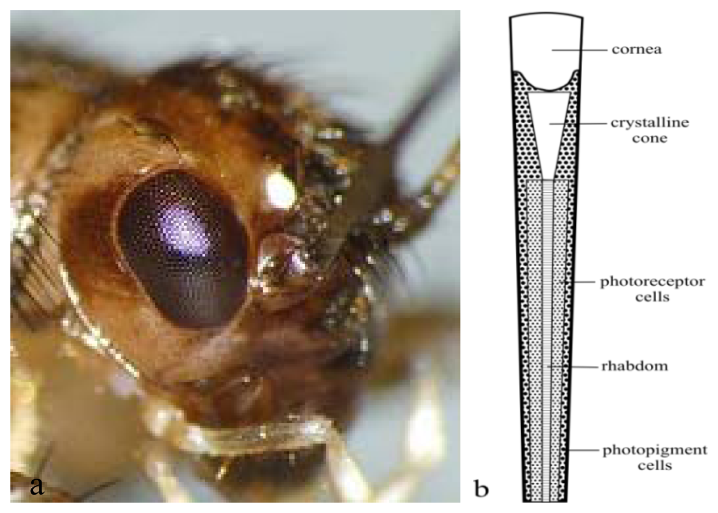
: Animal senses cover a broad range of signal types and signal bandwidths and have inspired various sensors and bioinstrumentation devices for biological and medical applications. Insects, such as desert ants and honeybees, for example, utilize polarized skylight pattern-based information in their navigation activities. They reliably return to their nests and hives from places many kilometers away. The insect navigation system involves the dorsal rim area in their compound eyes and the corresponding polarization sensitive neurons in the brain. The dorsal rim area is equipped with photoreceptors, which have orthogonally arranged small hair-like structures termed microvilli. These are the specialized sensors for the detection of polarized skylight patterns (e-vector orientation). Various research groups have been working on the development of novel navigation systems inspired by polarized skylight-based navigation in animals. Their major contributions are critically reviewed. One focus of current research activities is on imitating the integration path mechanism in desert ants. The potential for simple, high performance miniaturized bioinstrumentation that can assist people in navigation will be explored.
1. Introduction
Human and animals navigate for various needs—for finding food, for social reasons, for communication and others. Current navigation devices are mostly dependent on the global navigation satellite system (GNSS), the more fully operational system for global positioning compared to others. The variability of function and integration of the new generation of GNSS has increased the market demand for related products [1]. However its applications may be limited by the low precision of the signal under certain conditions such as in urban areas and in situations of intermittent coverage. Furthermore, the system is always at risk of being shut down during a conflict. A new system should be developed to overcome these limitations.
The development of a GPS-independent navigation system has been inspired by the skylight-based navigation employed by insects. These insects, with their tiny eyes and brains, are capable of navigating distances of hundred of meters (walking insects) [2] or many kilometers (flying insects) by utilizing the pattern of polarized skylight. Through replicating such insect navigation systems, it may be possible to provide a kind of “navigational sense” to people. The development of a bio-inspired polarized skylight navigation sensor that can expand the human sensory ability towards such a “navigational sense” necessitates the use of highly interdisciplinary bioinstrumentation. In order for this to operate effectively, there is a need to connect external devices to the human body. To connect the system with the human body, miniaturization of the devices needs to be performed. In this article existing bio-inspired polarized skylight-based navigation sensors are reviewed with the intention of examining whether it is possible to upgrade respective devices to miniaturized bioinstrumentation systems that can be utilized for human navigation, potentially in combination with established GPS-based systems, to overcome limitations of both approaches. Both through the development of GPS-independent navigation systems and improvements to current GPS systems bioinspiration of polarized skylight navigation sensors has already yielded tangible results. These devices have been tested for use as a navigational compass that can guide a mobile robot [3,4].
Lambrinos et al.[5] invented a GPS independent polarization compass model that mimics the principle of the desert ant navigation system. Chu and co-workers enhanced this polarization compass principle [4,6–9] and improved the error measurement. Further groups working in this field are Gao and Fan and their co-workers [10–16]. Lu and co-workers implemented polarized skylight detection mechanisms into existing GPS systems [17–19]. Fan et al.[10] implemented a new integrated navigation solution with polarized skylight with geomagnetism and GPS. Advanced miniaturized devices can then be linked to the human body (mainly ex corpore to avoid ethical issues) in order to expand the human sensory perception towards a polarized skylight-based “navigational sense”. This sensor would be very beneficial to humans, especially those who suffer from difficulties with their sight, are wheelchair bound or suffer from Parkinson's disease.
4. Algorithms
4.1. Algorithm for Measurement and Analysis for Coupled Photodetector-Linear Film Polarizer-Based Polarization Sensor
The output of polarization sensor is described by the following equation [5]:
The algorithm improvement is important for improving the polarization compass. From Equations (2–4), Zhao [9] eliminated the influence of the polarization degree, d, by presenting a new transform, where after simplification of ti, they got the value of output angle of the polarization sensor Si [Equation (10)] that was independent of d:
The output of the polarization sensor could also be described by using the mathematical description known as Stokes parameters (shown in Equation (11)) [109]. Stokes parameters were first introduced by G.G. Stokes in 1852, who described the polarization state in four quantities. As shown in Equation (11), the four quantities: S0, S1, S2 and S3 could be assumed to be polarization values obtained from Filters 1, 2, 3 and 4 respectively. Here, the first filter is an isotropic filter, passing all states of polarization, Filter 2 is passing the linear state of polarization in the horizontal direction, while Filter 3 passes the linear state of polarization at a 45° direction. Filter 4 filters the circular polarization state only:
Filters of Type 1 and Type 2 are found in the works of Lambrinos et al. and Chu and co-workers, where the polarization states could be represented as Equations (12) and (13):
The theoretical basis for the system error model of the polarized-skylight angle measurement model (POLAMM) has been developed by Li et al.[110]. The system error model of POLAMM was derived to improve the calculation accuracy of the polarized light navigation sensor. Through this system error model, the system error source parameters could be recognized, and the system error could be compensated to a major extent. From Equation (1), the output of three POL sensors is shown as follows:
According to the practical meaning, Equation (14) should satisfy (15):
By substituting Equation (17) into Equation (16), the equation of POLAMM could be obtained, as shown by Equation (18):
Here:
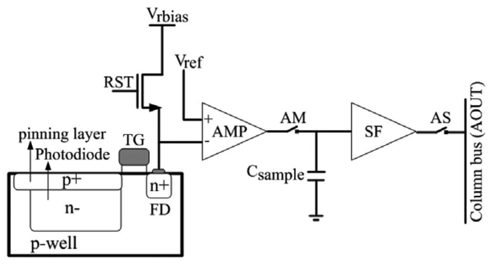
4.2. Algorithm of CMOS-Based Sensor
The measurement in CMOS-based sensors is performed by calculating the Stokes parameters [89,94]. The electromagnetic radiation travel is utilized as input signal. The mathematical representation of an electromagnetic wave propagating in the z direction is given by Equation (22):
4.3. Algorithm for Development of Ant Eye Model
Smith [111,112] developed an algorithm for a compass that was applied on robots and drones in light clouds. The working principle of this compass was inspired by the insect compound eye. The algorithm was created by measuring the position of the four points in the sky, where, i.e., the angle χ between the polarized e-vector and the meridian equals ±π/4. The azimuth of these four points is invariant to variable cloud cover, provided that polarized skylight is still detectable below the clouds. The sum of these four azimuth values can be turned into a celestial compass, which is useful for the robot or drone. Compared with the photoreceptor-based design, a compass that uses this design offers a simpler device that offers more accuracy during navigation under cloudy sky.
5. Integration System
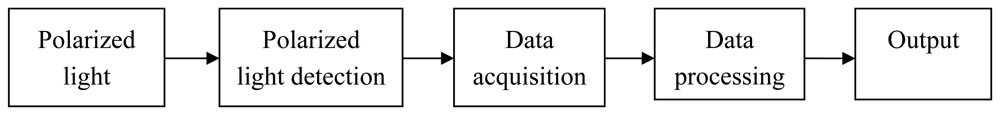
Lu et al.[113] introduced the polarized skylight integrated GPS-based navigation system in the three-dimensional world. The polarization measurement unit (POLMU) is a detection unit that consists of the mechanism and components of the polarization direction analyzer that was described in Section 3.1.2. By integrating the POLMU to the integrated GPS/INS navigation system, the attitude error correcting capabilities of the system was improved, producing better precision in the GPS/INS navigation system. Fan et al.[10] implemented a new integrated navigation solution with polarized skylight that assists with geomagnetism and GPS. The output of the analyzed polarization information is used as references in the measurement work of the integration system. By using a Kalman filter, the results of analyzed polarization information are combined with the results of the geomagnetism 3D compass to obtain the smallest error of angle results. By adjusting the results with GPS information, the final output results were obtained. The components of the polarization sensor are polarization direction analyzer, such as that described in Section 3.1.2, with the same mechanism.
6. Discussion
The insect navigation system, especially that of the desert ant, Cataglyphis, bees, locusts and crickets have offered useful insights into the development of polarization navigation sensors that have been utilized to assist the navigation of mobile robots (as described in Section 3). By further developing this robot polarization navigation sensor, it is possible that a new kind of human sense, a “navigational sense”, could be fabricated.
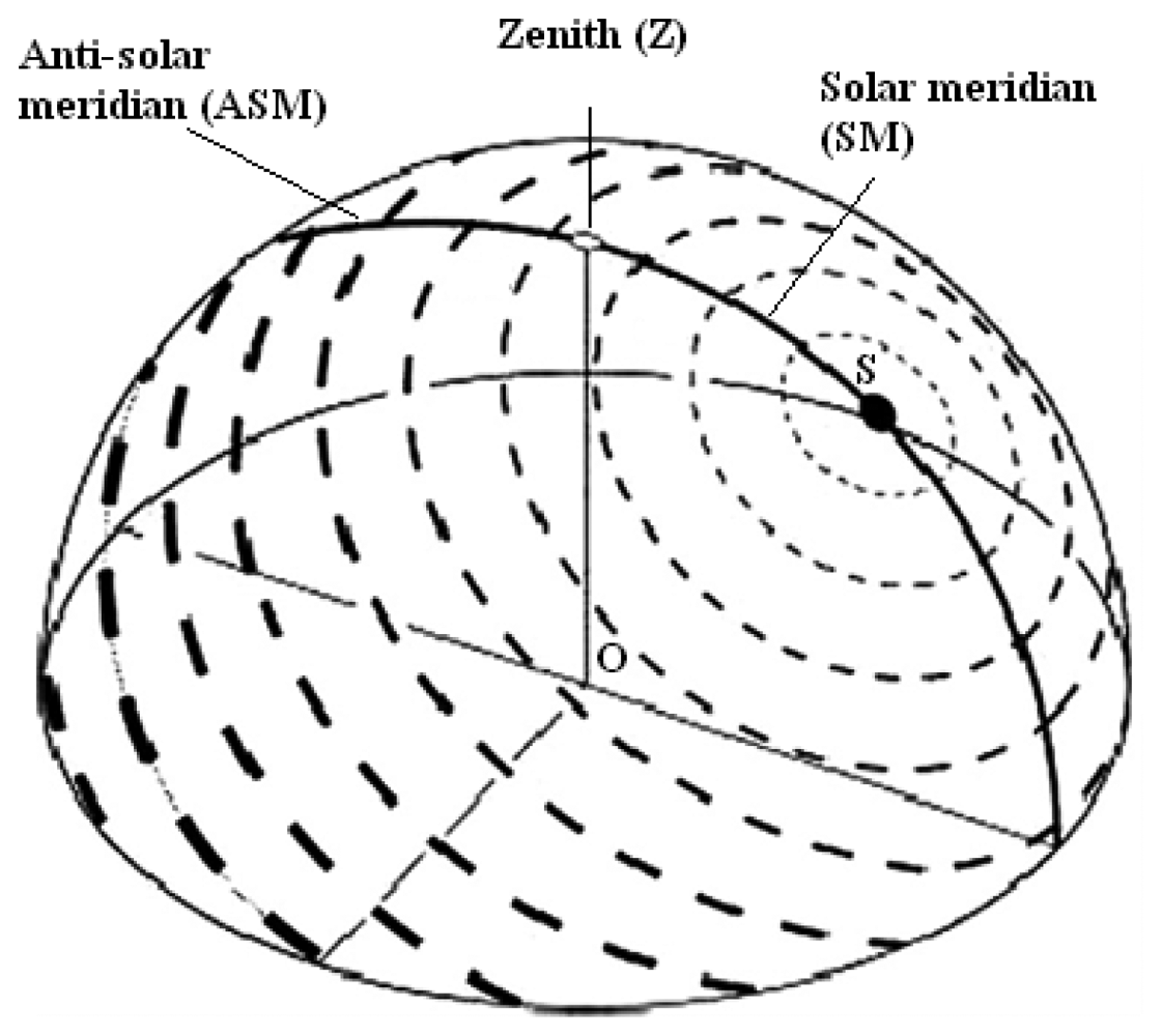
Insects, with their tiny eyes and brain, are capable of navigating over hundreds of meters through the utilization of the patterns of polarized skylight [2]. The dynamic properties of skylight polarization provide much useful information to any navigating animal and human utilizing specific devices. GNSS systems do not perform well under some conditions, and polarization based systems do not perform either under other conditions (e.g., indoors, night, artificial light). Both systems can be combined to bring the best of both worlds and cover the deficiencies of each other. The polarized skylight is appropriate to be used as the information in navigation activities because the predictor signal is simple with a static relationship between e-vector orientation and the sun's azimuth [36].
The qualitatively robust pattern of polarized skylight direction could be obtained under any condition and even in situations when the sun was not visible [114], such as under canopy and foliage [115], and during overcasts and heavy haze. This is because only a small section of clear sky is sufficient for the animals to obtain a compass bearing for accurate navigation [116]. The polarization angle pattern of this obscured sky is determined predominantly by scattering on cloud particles themselves [114]. Furthermore, the detection of polarization of downwelling skylight under clouds or canopies is most advantageous in the UV range, where the degree of polarization is lower than the threshold of polarization sensitivity in animals [2,117].
As described in this article, there are three major types of polarization navigation sensor designs that have been utilized in the robotic field: photodiode—linear film polarizer integrated-based design, camera and external polarizer-based design, and DoFP polarimeter-based CMOS sensor design. For the first design, the performance of the devices that were reported in this article is described as shown in Table 4. In the earlier project of this design, the error in the movement of the polarization navigation sensor mounted robot was approximately 13.5 cm, smaller than the error obtained in the latter project, which was 28 cm. However, the output angle in the latter project shows the smaller error than the earlier project, about ±1.3° in difference.
In the second design, the degree of polarization was not compensated. The polarization differential image or polarization summation image is the main task in the third design. This design also studied the image and the variation in the degree of polarization with respect to the orientation. In this design, the degree of polarization behavior with the orientation angle is evaluated. The degree of polarization information from this evaluation could be used to obtain the orientation angle for compass cue application. This third design offers a simpler computation calculation step and provides a system that is easier to integrate with other devices.
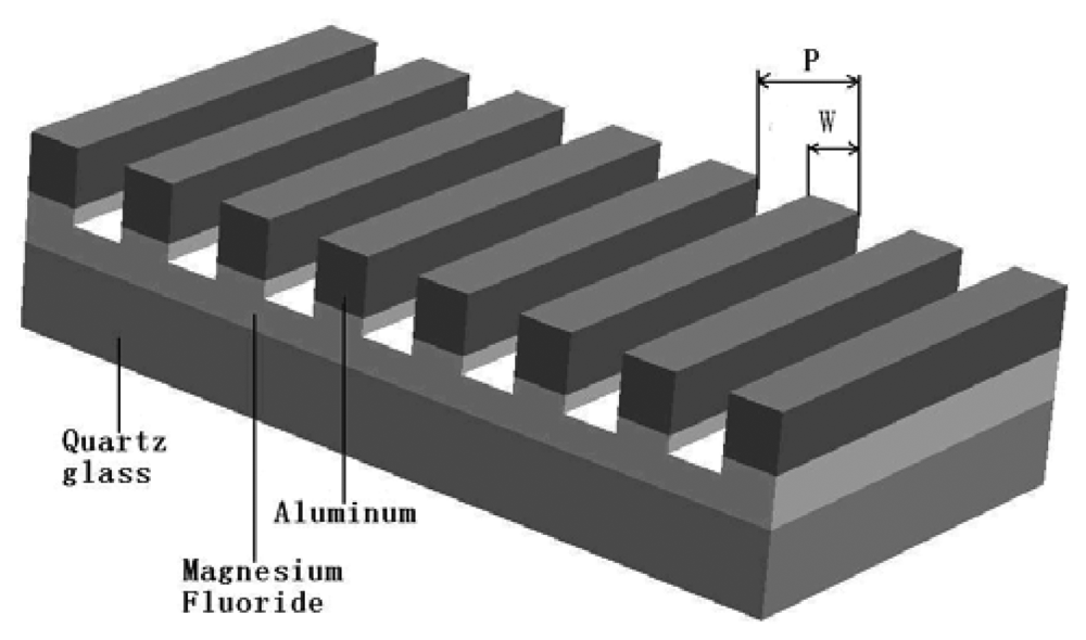
In order to develop a human “navigational sense”, polarized skylight sensor research in robotics can be applied to bioinstrumentation research through the use of miniaturization technology. In insects, the most sensitive photoreceptor within polarization detection is UV (bees, flies, ants) and blue photoreceptor (cricket) [43]. UV skylight is in a wavelength range from 330 to 350 nm [41,118], while blue skylight has a wavelength of about 450 nm [118]. As described in Section 3.3.3, for the wire grid micropolarizer to effectively detect the polarization signal, a wire grid pitch should be less than 300 nm. By applying the principle of the central processing stage of insect visual systems (see Section 2.5), the accuracy of the polarization navigation sensor could be increased by raising the number of the polarizing direction axes of the polarizer. Due to the small size and integration process, the multiple polarizing direction axes of the array of wire grid micropolarizers-based navigation sensor could only be developed using nanofabrication technology.
The extremely sensitive e-vector detection system used in crickets can be imitated through the development of a polarization navigation sensor for higher sensitivity. Crickets are active during daytime and at night. The crickets' threshold response possess at lower quantum flux induction than the threshold response by ants and honeybees. In crickets, the threshold response to the radiant quantum flux is about 2.5 × 10⁷ quanta cm−2·s−1 at 433 nm [43], where the effective quantum flux under the clear, moonless night sky (2 × 10⁸ quanta cm−2·s−1 at 380–500 nm) [119]. During daytime, the threshold for e-vector orientation of honey bees (Apis mellifera) for UV stimulus is about 1010–1011 quanta sm−2·s−1, much higher than that demonstrated by crickets.
7. Conclusions and Outlook·
The implementation of a bio-inspired polarized skylight navigation sensor that can expand the human sensory ability towards a “navigational sense” necessitates the creation of a connection between external devices and the human body. To enable this, miniaturization and integration of existing devices need to be performed, something that is possible using miniaturization technology. Through the application of miniaturization technology, the existing polarized skylight-based navigation sensor that is typically utilized for robot navigation could be enhanced for bioinstrumentation application by integrating them with various techniques, devices and system such as geo-informatics system (GIS) system. Health quality of patient that equipped with the polarization based “navigational sense” could be monitored by the central server at any time continuously or when requested, especially during their outdoor activities [120]. The central server, which is connected to at least three parties (patient, GIS and rescue center), will take first action if the patient's health quality decrease. For example, if the patient have heart problem, the patient's health monitoring device and “navigational sense” will send the health condition data and position data respectively to the central server. As the patient's health quality getting worse, the central server ready to send the ambulance to patient's location.
Weaknesses in the current engineering system when compared with the perfection of natural systems, were highlighted in this review. As such, new theories need to be developed that are capable of improving the approach. MEMS technology can potentially serve to create a system that can more accurately replicate the perfect natural systems with engineering systems or devices that have high functionality and intelligence. A bio-inspired polarized skylight-based MEMS navigation sensor would be very beneficial to humans, especially those who suffer from difficulties with their sight, are wheelchair bound or suffer from Parkinson's disease.
Acknowledgments
This work was supported by an Arus Perdana Project from the National University of Malaysia. Project number UKM-AP-NBT-16-2010.
References
- Mendizabal, J.; Berenguer, R.; Melendez, J. GPS and Galileo: Dual RF Front-End Receiver Design, Fabrication, and Test; Mc Graw Hill: New York, NY, USA, 2009; pp. 1–26. [Google Scholar]
- Wehner, R. Desert ant navigation: How miniature brains solve complex tasks. J. Comp. Physiol. A 2003, 189, 579–588. [Google Scholar]
- Shashar, N.; Sabbah, S.; Cronin, T.W. Transmission of linearly polarized light in seawater: Implications for polarization signaling. J. Exp. Biol. 2004, 207, 3619–3628. [Google Scholar]
- Chu, J.; Zhao, K.; Zhang, Q.; Wang, T. Construction and performance test of a novel polarization sensor for navigation. Sens. Actuators A: Phys. 2008, 148, 75–82. [Google Scholar]
- Lambrinos, D.; Möller, R.; Labhart, T.; Pfeifer, R.; Wehner, R. A mobile robot employing insect strategies for navigation. Robot. Auton. Syst. 2000, 30, 39–64. [Google Scholar]
- Chu, J.; Zhao, K.; Wang, T.; Zhang, Q. Research on a Novel Polarization Sensor for Navigation. Proceedings of International Conference on Information Acquisition, ICIA'07, Jeju Island, Korea, 9–11 July 2007; pp. 241–246.
- Chu, J.; Zhao, K.; Zhang, Q.; Wang, T. Design of a Novel Polarization Sensor for Navigation. Proceedings of International Conference on Mechatronics and Automation, ICMA'07, Harbin, China, 5–8 August 2007; pp. 3161–3166.
- Chu, J.; Wang, H.; Chen, W.; Li, R. Application of a Novel Polarization Sensor to Mobile Robot Navigation. Proceedings of International Conference on Mechatronics and Automation, ICMA'09, Changchun, China, 9–12 August 2009; pp. 3763–3768.
- Zhao, K.; Chu, J.; Wang, T.; Zhang, Q. A novel angle algorithm of polarization sensor for navigation. IEEE T. Instrum. Meas. 2009, 58, 2791–2796. [Google Scholar]
- Fan, Z.; Gao, J.; Pan, D.; Cui, S. The implementation of a new integrated navigation solution with polarized-light assisting with geomagnetism and GPS. Geomatics Infor. Sci. Wuhan Univ. 2009, 11, 1324–1327. [Google Scholar]
- Rodrigo, T. Navigational strategies and models. Psicológica 2002, 23, 3–32. [Google Scholar]
- Brunner, D.; Labhart, T. Behavioural evidence for polarization vision in crickets. Physiol. Entomol. 1987, 12, 1–10. [Google Scholar]
- Mappes, M.; Homberg, U. Behavioral analysis of polarization vision in tethered flying locusts. J. Comp. Physiol. A 2004, 190, 61–68. [Google Scholar]
- von Philipsborn, A.; Labhart, T. A behavioral study of polarization vision in the fly. Musca domestica. J. Comp. Physiol. A 1990, 167, 737–743. [Google Scholar]
- Dacke, M.; Nordström, P.; Scholtz, C.H. Twilight orientation to polarised light in the crepuscular dung beetle. Scarabaeus zambesianus. J. Exp. Biol. 2003, 206, 1535–1543. [Google Scholar]
- Somanathan, H.; Kelber, A.; Borges, R.; Wallén, R.; Warrant, E. Visual ecology of Indian Capenter bees II: Adaptations of eyes and ocelli to nocturnal and diurnal lifestyles. J. Comp. Physiol. A 2009, 195, 571–583. [Google Scholar]
- Collett, M.; Collett, T.S. How do insects use path integration for their navigation? Biol. Cybern. 2000, 83, 245–259. [Google Scholar]
- Labhart, T.; Meyer, E.P. Neural mechanisms in insect navigation: Polarization compass and odometer. Cur. Opin. Neurobiol. 2002, 12, 707–714. [Google Scholar]
- Wehner, R.; Sriinivasan, M.V. Path Integration in Insects. In The Neurobiology of Spatial Behavior; Jeffery, K.J., Ed.; Oxford University Press: Oxford, UK, 2003; pp. 9–30. [Google Scholar]
- Homberg, U. In search of the sky compass in the insect brain. Naturwissenschaften 2004, 91, 199–208. [Google Scholar]
- Reppert, S.M.; Zhu, H.; White, R.H. Polarized light helps monarch butterflies navigate. Curr. Biol. 2004, 14, 155–158. [Google Scholar]
- Stalleicken, J.; Labhart, T.; Mouritsen, H. Physiological characterization of the compound eye in monarch butterflies with focus on the dorsal rim area. J. Comp. Physiol. A 2005, 192, 321–331. [Google Scholar]
- Kohler, M.; Wehner, R. Idiosyncratic route-based memories in desert ants, Melophorus bagoti How do they interact with path-integration vectors? Neurobiol. Learn. Mem. 2005, 83, 1–12. [Google Scholar]
- Narendra, A. Homing strategies of the Australian desert ant Melophorus bagoti. II. Interaction of the path integrator with visual cue information. J. Exp. Biol. 2007, 210, 1804–1812. [Google Scholar]
- Graham, P.; Cheng, K. Ants use the panoramic skyline as a visual cue during navigation. Curr. Biol. 2009, 19, 935–937. [Google Scholar]
- Wystrach, A.; Schwarz, S.; Schultheiss, P.; Beugnon, G.; Cheng, K. Views, landmark and routes: how do desert ants negotiate an abstacle course? J. Comp. Physiol. A 2011, 197, 167–179. [Google Scholar]
- Graham, P.; Cheng, K. Which portion of the natural panorama is used for view-based navigation in the Australian desert ant? J. Comp. Physiol. A 2009, 195, 681–689. [Google Scholar]
- Labhart, T. Polarization-opponent interneurones in the insect visual system. Nature 1988, 331, 435–437. [Google Scholar]
- Labhart, T. Polarization-sensitive interneurons in the optic lobe of the desert ant. Cataglyphis bicolor. Naturwissenschaften 2000, 87, 133–136. [Google Scholar]
- Wehner, R. The Perception of Polarized Light. In The Biology of Photoreceptor; Cambridge University Press: Cambridge, UK, 1983; pp. 331–369. [Google Scholar]
- Strutt, J. On the light from the sky, its polarization and colour. Philos. Mag. 1871, 41, 107–120. [Google Scholar]
- Wehner, R. The Ant's Celestial Compass System: Spectral and Polarization Channels. In Orientation and Communication In Arthropods; Lehrer, M., Ed.; Birkhäuser: Basel, Switzerland, 1997. [Google Scholar]
- Chandrasekhar, S. Radiative Transfer; Oxford University Press: London, UK, 1950; p. 393. [Google Scholar]
- Sekera, Z. Reciprocity relations for diffuse reflection and transmission radiative transfer in planetary atmosphere. Astrophysics 1970, 162, 3–16. [Google Scholar]
- Horváth, G. How do water insects find their aquatic habitat? Természet Világa Special Issue 1995, 125, 44–49. [Google Scholar]
- Brines, M.L. Dynamic patterns of skylight polarization as clock and compass. J. Theor. Biol. 1980, 86, 507–512. [Google Scholar]
- Rodieck, R.W. The Vertebrate Retina. Principle of Structure and Function; W.H. Freeman and Co.: San Francisco, CA, USA, 1973. [Google Scholar]
- Kirschfeld, K. The absolute sensitivity of lens and compound eyes. Z. Noturforsch 1974, 29, 592–596. [Google Scholar]
- Duelli, P.; Wehner, R. The spectral sensitivity of polarized light orientation in Cataglyphis bicolor (Formicidae, Hymenoptera). J. Comp. Physiol. 1973, 86, 37–53. [Google Scholar]
- Labhart, T. Specialized photoreceptors at the dorsal rim of the honeybee's compound eye-polarizational and angular sensitivity. J. Comp. Physiol. 1980, 141, 19–30. [Google Scholar]
- Hardie, R.C. Properties of photoreceptor-R7 and photoreceptor-R8 in dorsal marginal ommatidia in the compound eyes of Musca and Calliphora. J. Comp. Physiol. 1984, 154, 157–165. [Google Scholar]
- Labhart, T.; Hodel, B.; Valenzuela, I. The physiology of the cricket's compound eye with particular reference to the anatomically specialized dorsal rim area. J. Comp. Physiol. 1984, 155, 289–296. [Google Scholar]
- Herzmann, D.; Labhart, T. Spectral sensitivity and absolute threshold of polarization vision in crickets: A behavioral study. J. Comp. Physiol. A 1989, 165, 315–319. [Google Scholar]
- Menzel, R.; Snyder, A.W. Photoreceptor Optics-Structure and Function of Photoreceptor; Hopper, W.L., Markl, H., Ziegler, H., Eds.; Springer-Verlag: Berlin, Germany, 1983. [Google Scholar]
- Labhart, T. Specialized photoreceptors at the dorsal rim of the honeybee's compound eye—Polarizational and angular sensitivity. J. Comp. Physiol. 1980, 141, 19–30. [Google Scholar]
- Pirih, P.; Arikawa, K.; Stavenga, D.G. An expanded set of photoreceptors in the Eastern Pale Clouded Yellow butterfly. Colias erate. J. Comp. Physiol. A 2010, 196, 501–517. [Google Scholar]
- Stavenga, D.G.; Arikawa, K. Photoreceptor spectral sensitivities of the Small White butterfly Pieres rapae crucivora interpreted with optical modelling. J. Comp. Physiol. A 2011, 197, 373–385. [Google Scholar]
- Briscoe, A.D.; Chittka, L. The evolution of color vision in insects. Annu. Rev. Entomol. 2001, 46, 471–510. [Google Scholar]
- Rossel, S.; Wehner, R. Celestial orientation in bees: The use of spectral cues. J. Comp. Physiol. A 1984, 155, 605–613. [Google Scholar]
- Wehner, R.; Strasser, S. The POL area of the honey bee's eye: Behavioral evidence. Physiol. Entomol. 1985, 10, 337–349. [Google Scholar]
- Wehner, R. Himmelsnavigation bei insekten neurophysiologie und verhalten. Neujahrsbl Naturforsch Ges Zürich 1982, 184, 1–132. [Google Scholar]
- Labhart, T. The electrophysiology of photoreceptors in different eye regions of the desert ant. Cataglyphi bicolor. J. Comp. Physiol. A 1986, 158, 1–7. [Google Scholar]
- Hardie, R.C. Functional Organization of the Fly Retina. In Progress in Sensory Physiology; Ottoson, D., Ed.; Spinger Verlag: New York, NY, USA, 1985; pp. 1–79. [Google Scholar]
- Labhart, T.; Meyer, E.P. Detectors for polarized skylight in insects: A survey of ommatidial specializations in the dorsal rim area of the compound eye. Microsc. Res. Tech. 1999, 47, 368–379. [Google Scholar]
- Labhart, T.; Baumann, F.; Bernard, G.D. Specialized ommatidia of the polarization-sensitive dorsal rim area in the eye of monarch butterflies have non-functional reflecting tapeta. Cell Tissue Res. 2009, 338, 391–400. [Google Scholar]
- Meyer, E.P.; Domanico, V. Microvillar orientation in the photoreceptors of the ant. Cataglyphis bicolor. Cell Tissue Res. 1999, 295, 355–361. [Google Scholar]
- Rossel, S. Navigation by bees using polarized light. Comp. Biochem. Physio. A 1993, 104, 695–708. [Google Scholar]
- Nilsson, D.E.; Labhart, T.; Meyer, E.P. Photoreceptor design and optical properties affecting polarization sensitivity in ants and crickets. J. Comp. Physiol. A 1987, 161, 645–658. [Google Scholar]
- Homberg, U.; Hofer, S.; Pfeiffer, K.; Gebhardt, S. Organisation and neural connections of the anterior optic tubercle in the brain of the locust. Schistocerca gregaria. J. Comp. Neurol. 2003, 462, 415–430. [Google Scholar]
- Wehner, R.; Bernard, G.D. Intracellular optical physiology II. Polarization sensitivity. J. Comp. Physiol. 1980, 137, 205–214. [Google Scholar]
- Mote, M.I.; Wehner, R. Functional characteristics of photoreceptors in the compound eye and ocellus of the desert ant. Cataglyphis bicolor. J. Comp. Physiol. A 1980, 137, 63–71. [Google Scholar]
- Wolf, R.; Gebhardt, B.; Gademann, R.; Heisenberg, M. Polarization sensitivity of course control in. Drosophila melanogaster. J. Comp. Physiol. A 1980, 139, 177–191. [Google Scholar]
- Dacke, M.; Doan, T.A.; O'carroll, D.C. Polarized light detection in spiders. J. Exp. Biol. 2001, 204, 2481–2490. [Google Scholar]
- Cronin, T.W.; Shashar, N.; Caldwell, R.L.; Marshall, J.; Cheroske, A.G.; Chiou, T. -H. Polarization vision and its role in biological signaling. Integr. Comp. Biol. 2003, 43, 549–558. [Google Scholar]
- Mäthger, L.M.; Shashar, N.; Hanlon, R.T. Do The cephalopods communicate using polarized light reflections from their skin? J. Exp. Biol. 2009, 212, 2133–2140. [Google Scholar]
- Ramskou, T. Solstenen. Skalk 1967, 2, 16–17. [Google Scholar]
- Karlsen, L.K. Secrets of the Viking Navigators; One Earth Press: Seattle, WA, USA, 2003. [Google Scholar]
- Chahl, J.; Mizutani, A. Biomimetic attitude and orientation sensors. IEEE Sens. J 2012, 12, 289–297. [Google Scholar]
- Fermüller, C.; Aloimonos, Y. Ambiguity in structure from motion: Sphere versus plane. Int. J. Comput. Vision 1998, 28, 137–154. [Google Scholar]
- Feng, W.; Gao, J.; Ren, S.; Wu, K. Modeling and simulation of Cataglyphis compound eye. Chin. J. Scientific Instrum. 2008, 29, 605–608. [Google Scholar]
- Usher, K.; Ridley, P.; Corke, P. A Camera as a Polarized Light Compass: Preliminary Experiments. Proceedings of Australian Conference on Robotics and Automation, Sydney, Australia, 14–15 November 2001; pp. 116–120.
- Carey, N.; Sturzl, W. An Insect-Inspired Omnidirectional Vision System Including UV-Sensitivity and Polarisation. IEEE International Conference on Computer Vision Workshops (ICCV Workshops), Barcelona, Spain, 6– 13 November 2011; pp. 312–319.
- Xiaojin, Z.; Boussaid, F.; Bermak, A.; Chigrinov, V.G. Thin photo-patterned micropolarizer array for CMOS image sensors. IEEE Photon. Tech. L 2009, 21, 805–807. [Google Scholar]
- Tokuda, T.; Yamada, H.; Sasagawa, K.; Ohta, J. Polarization-Analyzing Image Sensor Based on Standard CMOS Technology. Proceedings of International Solid-State Sensors, Actuators and Microsystems Conference, TRANSDUCERS 2009, Denver, CO, USA, 21– 25 June 2009; pp. 331–333.
- Tokuda, T.; Yamada, H.; Sasagawa, K.; Ohta, J. Polarization-analyzing CMOS Image Sensor Using Monolithically Embedded Polarizer for Microchemistry Systems. IEEE International Symposium on Circuits and Systems, ISCAS '09, Taipei, Taiwan, 24– 27 May 2009; pp. 313–316.
- Gruev, V.; Perkins, R.; York, T. CCD polarization imaging sensor with aluminum nanowire optical filters. Opt. Express 2010, 18, 19087–19094. [Google Scholar]
- Gruev, V.; Van der Spiegel, J.; Engheta, N. Dual-tier thin film polymer polarization imaging sensor. Opt. Express 2010, 18, 19292–19303. [Google Scholar]
- Perkins, R.; Gruev, V. Signal-to-noise analysis of Stokes parameters in division of focal plane polarimeters. Opt. Express 2010, 18, 25815–25824. [Google Scholar]
- Sarkar, M.; San Segundo Bello, D.; van Hoof, C.; Theuwissen, A. Integrated Polarization Analyzing CMOS Image Sensor for Autonomus Navigation Using Polarized Light. Proceedings of 5th IEEE International Conference Intelligent Systems, IS '10, London, UK, 7– 9 July 2010; pp. 224–229.
- Sarkar, M.; San Segundo Bello, D.; Van Hoof, C.; Theuwissen, A.J.P. Integrated polarization-analyzing CMOS image sensor for detecting the incoming light ray direction. IEEE Trans. Instrum. Meas. 2011, 60, 2759–2767. [Google Scholar]
- Andreou, A.G.; Kalayjian, Z.K. Polarization imaging: Principles and integrated polarimeters. IEEE Sens. J. 2002, 2, 566–576. [Google Scholar]
- Meng, F.; Chu, J.; Han, Z.; Zhao, K. The Design of the Sub-Wavelength Wire-Grid Polarizer. Poceedings of 7th IEEE Conference on Nanotechnology, IEEE-NANO'07, Hong Kong, 2– 5 August 2007; pp. 942–946.
- Tokuda, T.; Yamada, H.; Sasagawa, K.; Ohta, J. Polarization-analyzing CMOS image sensor with monolithically embedded polarizer for microchemistry systems. IEEE Trans. Biomed. Circ. S. 2009, 3, 259–266. [Google Scholar]
- Momeni, M.; Titus, A.H. An analog VLSI chip emulating polarization vision of octopus retina. IEEE Trans. Neural Netw. 2006, 17, 222–232. [Google Scholar]
- Takano, K.; Morimoto, I.; Yokoyama, H.; Hangyo, M. Wire-Grid Polarizer in the Terahertz Region Fabricated by Nanoimprint Technology. Poceedings of 35th International Conference on Infrared Millimeter and Terahertz Waves, IRMMW-THz'10, Rome, Italy, 5–10 September 2010; pp. 1–2.
- Yang, Z.Y.; Zhao, M.; Dai, N.L.; Yang, G.; Long, H.; Li, Y.H.; Lu, P.X. Broadband polarizers using dual-layer metallic nanowire grids. IEEE Photonics Technol. Lett. 2008, 20, 697–699. [Google Scholar]
- Hansen, D.; Gardner, E.; Perkins, R. The display applications and physics of the ProFlux™ wire grid polarizer. SID Digest 2002, 33, 730–733. [Google Scholar]
- Chen, C.M.; An, T.P.; Hung, Y.M.; Sung, C.K. Fabricating insertion structures for metallic wire grid polarizers by nanoimprint and CMP process. Microelectron. Eng. 2011, 88, 2135–2140. [Google Scholar]
- Suzuki, M.; Takada, A.; Yamada, T.; Hayasaka, T.; Sasaki, K.; Takahashi, E.; Kumagai, S. Antireflection coatings with FeSi2 layer: Application to low-reflectivity wire grid polarizers. Thin Solid Films 2011, 519, 8485–8489. [Google Scholar]
- Kim, J.S.; Lee, K.D.; Ahn, S.W.; Kim, S.H.; Park, J.D.; Lee, S.E.; Yoon, S.S. Fabrication of nanowire polarizer by using nanoimprint lithography. J. Korean Phys. Soc. 2004, 45, S890–S892. [Google Scholar]
- Doumuki, T.; Tamada, H. An Aluminum-Wire Grid Polarizer Fabricated onto a Gallium Arsenide Photodiode. Proceedings of Conference on Lasers and Electro-Optics, CLEO '97, Baltimore, MD, USA, 18– 23 May 1997; pp. 23–24.
- Wang, J.; Walters, F.; Liu, X.; Sciortino, P.; Deng, X. High-performance, large area, deep ultraviolet to infrared polarizers based on 40 nm line/78 nm space nanowire grids. Appl. Phys. Lett. 2007, 90. [Google Scholar]
- Yoon, Y.T.; Lee, H.S.; Lee, S.S.; Kim, S.H.; Park, J.D.; Lee, K.D. Color filter incorporating a subwavelength patterned grating in poly silicon. Opt. Express 2008, 16, 2374–2380. [Google Scholar]
- Chen, C.M.; Sung, C.K. Fabricating metallic wire grating inside a polymeric substrate by insertion nanoimprint. Microelectron. Eng. 2010, 87, 872–875. [Google Scholar]
- Meng, F.; Luo, G.; Maximov, I.; Montelius, L.; Chu, J.; Xu, H. Fabrication and characterization of bilayer metal wire-grid polarizer using nanoimprint lithography on flexible plastic substrate. Microelectron. Eng. 2011, 88, 3108–3112. [Google Scholar]
- Xue, Y.; Wang, C.; Zhang, G.; Cao, B. Compound polarized wavelength filters with a single subwavelength structure. Optic. Commun. 2011, 284, 501–509. [Google Scholar]
- Yoon, Y.T.; Lee, S.S.; Lee, B.S. Nano-patterned visible wavelength filter integrated with an image sensor exploiting a 90-nm CMOS process. Photon. Nanostruct. 2012, 10, 54–59. [Google Scholar]
- Tyo, J.S.; Goldstein, D.L.; Chenault, D.B.; Shaw, J.A. Review of passive imaging polarimetry for remote sensing applications. Appl. Optic. 2006, 45, 5453–5469. [Google Scholar]
- Tyo, J.S.; Hayat, M.M. Calibration and Compensation of Instrumental Errors in Imaging Polarimeters; AFOSR/NE: Arlington, VA, USA, 2007; pp. 1–6. [Google Scholar]
- Ratliff, B.M.; Tyo, J.S.; Black, W.T.; Boger, J.K.; Bowers, D.L. Polarization visual enhancement technique for LWIR microgrid polarimeter imagery. Proc. SPIE 2008, 6972. [Google Scholar]
- Bowers, D.L.; Boger, J.K.; Wellems, L.D.; Ortega, S.E.; Fetrow, M.P.; Hubbs, J.E.; Black, W.T.; Ratliff, B.M.; Tyo, J.S. Unpolarized calibration and nonuniformity correction for long-wave infrared microgrid imaging polarimeters. Opt. Eng. 2008, 47. [Google Scholar]
- Ratliff, B.M.; Tyo, J.S.; Boger, J.K.; Black, W.T.; Bowers, D.L.; Fetrow, M.P. Dead pixel replacement in LWIR microgrid polarimeters. Opt. Express 2007, 15, 7596–7609. [Google Scholar]
- Azzam, R.M.A.; Elminyawi, I.M.; El-Saba, A.M. General analysis and optimization of the four-detector photopolarimeter. J. Opt. Soc. Am. A 1988, 5, 681–689. [Google Scholar]
- Goldstein, D.H.; Chipman, R.A. Error analysis of a Mueller matrix polarimeter. J. Opt. Soc. Am. A 1990, 7, 693–700. [Google Scholar]
- Ratliff, B.M.; LaCasse, C.F.; Tyo, J.S. Interpolation strategies for reducing IFOV artifacts in microgrid polarimeter imagery. Opt. Express 2009, 17, 9112–9125. [Google Scholar]
- Gao, S.; Gruev, V. Bilinear and bicubic interpolation methods for division of focal plane polarimeters. Opt. Express 2011, 19, 26161–26173. [Google Scholar]
- Gao, S.; Gruev, V. Gradient Based Interpolation for Division of Focal Plane Polarization Imaging Sensors. Proceedings of IEEE International Symposium on Circuits and Systems, ISCAS '12, Seoul, Korea, 20– 23 May 2012; pp. 1855–1858.
- Xu, X.; Kullkarni, M.; Nehoirai, A.; Gruev, V. A correlation-based interpolation algorithm for division-of-focal-plane polarization sensors. Proc. SPIE 2012, 8364. [Google Scholar]
- Hecht, E. Optics; Addison Wesley Longman Inc.: Reading, MA, USA, 1998; pp. 366–367. [Google Scholar]
- Li, M.M.; Lu, H.Q.; Yin, H.; Huang, X.L. Calibration and Error Analysis for Polarized-Light Navigation Sensor. Proceedings of International Conference on Electric Information and Control Engineering, ICEICE '11, Wuhan, China, 15–17 April 2011; pp. 217–220.
- Smith, F.J. A New Algorithm for Navigation by Skylight Based on Insect Vision. Proceedings of 1st International Conference on Bio-inspired Systems and Signal Processing, BIOSIGNALS '08, Funchal, Madeira, Portugal, 28–31 January 2008; pp. 185–190.
- Smith, F.J. Insect Navigation by Polarized Light. Proceedings of 2nd International Conference on Bio-Inspired Systems and Signal Processing, BIOSIGNALS '09, Porto, Portugal, 14–17 January 2009; pp. 363–368.
- Lu, H.; Huang, X.; Yin, H. Principles and Applications of Polarized-Light-Aided Attitude Determination in Integrated Navigation. Proceedings of Chinese Control Conference, CCC'06, Harbin, China, 7–11 August 2006; pp. 483–488.
- Hegedus, R.; Akesson, S.; Horvath, G. Polarization patterns of thick clouds: Overcast skies have distribution of the angle of polarization similar to that of clear skies. J. Opt. Soc. Am. A 2007, 24, 2347–2356. [Google Scholar]
- Hegedüs, R.; Bárta, A.; Bernáth, B.; Meyer-Rochow, V.B.; Horváth, G. Imaging polarimetry of forest canopies: How the azimuth direction of the sun, occluded by vegetation, can be assessed from the polarization pattern of the sunlit foliage. Appl. Optic. 2007, 46, 6019–6032. [Google Scholar]
- Dacke, M.; Nilsson, D.E.; Warrant, E.J.; Blest, A.D.; Land, M.F.; O'Caroll, D.C. Built-in polarizers form part of a compass organ in spiders. Nature 1999, 401, 470–473. [Google Scholar]
- Barta, A.; Horvath, G. Why is it advantageous for animals to detect celestial polarization in the ultraviolet? Skylight polarization under clouds and canopies is strongest in the UV. J. Theor. Biol. 2004, 226, 429–437. [Google Scholar]
- Seliger, H.H.; Lall, A.B.; Biggley, W.H. Blue through UV polarization sensitivities in insects: Optimizations for the range of atmospheric polarization conditions. J. Comp. Physiol. A 1994, 175, 475–486. [Google Scholar]
- Munz, F.W.; McFarland, W.N. Evolutionary Adaptations of Fishes to the Photic Environment. In Handbook of Sensory Physiology VII/5; Crescitelli, F., Ed.; Springer: Berlin/Heidelberg, Germany, 1977; pp. 193–307. [Google Scholar]
- Karman, S.B.; Diah, S.Z.M.; Futterknecht, O.; Gebeshuber, I.C. Towards A “Navigational Sense” for Humans: Biomimetic Polarized Light Based Navigation System. Proceedings of Applied Geoinformatics for Society and Environment, AGSE'12, Johor Bahru, Malaysia, 16–20 July 2012; pp. 71–76.
Glossary
| arthropods | animals lacking a backbone, with jointed limbs and a segmented body with an exoskeleton made of chitin. |
| Cataglyphis | a genus of ants |
| cephalopods | molluscs such as octopus, squid and cuttlefish |
| chromatophore | a cell or cell organelle that contains pigment |
| Coleoptera | beetles |
| cornea | transparent part in front of the eye |
| diurnal | active during the day |
| dorsal | the top, back or uppermost surface of an animal oriented with its head forward |
| egocentric | self-centred |
| Gryllus | a genus of crickets |
| Hemiptera | insects such as cicadas, aphids, planthoppers or shield bugs |
| homochromatic | containing or using only one colour |
| iridophore | a pigment cells that reflecting light |
| lamina | a thin layer, plate, or scale of sedimentary rock, organic tissue, or other material |
| Lepidoptera | insects such as butterflies and moths |
| Medulla | the inner region of an organ or tissue |
| microvilli | small ‘hairs’, component of insect photoreceptors |
| monochromatic | containing or using only one colour |
| ocellus | simple eye: an eye having a single lens |
| odometer (odograph) | device that indicates the distance travelled |
| ommatidium | optical unit in compound eyes |
| proprioreceptive | ability to sense stimuli arising within the body regarding position, motion and equilibrium |
| protrusion | something that protrudes |
| rhabdom | light guide in insect compound eyes |
| rhabdomere | reflective inner border of rhabdom |
| tapetum | reflective layer in the eyes of many animals, causing them to shine in the dark |
| tubercle | small rounded projection or protuberance, esp. on a bone or on the surface of an animal or plant |
| ventral | of, on, or relating to the underside of an animal or plant |


| Animals | Organ | Mechanism |
|---|---|---|
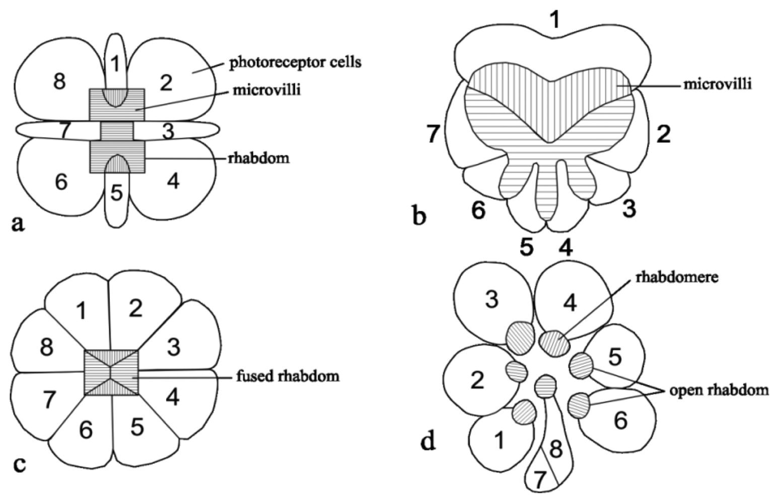
| Honey bees(Apis mellifera, Apis cerana) [54,60] | Compound eyes, ommatidia of the dorsal rim area (DRA) | RD: two populations of orthogonally arranged rhabdomeres; not twistedPR: UV receptor absorbing photopigments for polarization detection, maximum sensitivity for skylight polarized parallel to the microvilliMV: aligned in parallel along the length of each photoreceptor cell; microvilli orientation in a fan-like pattern |
| Desert ants(Cataglypis bicolor, C. fortis)[52,54,58,61] | Compound eyes, ommatidia of the DRA | RD: distal tips are dumb-bell shape and fused rhabdomPR: Polarization vision is mediated by UV receptor cells only; mutually perpendicular microvilliMV: aligned in parallel along the longitudinal axes of cells; microvilli orientation in a fan-like pattern |
| Cricket(Gryllus campestris) [18,58] | Compound eyes, ommatidia of the DRA | RD: fused and an elongated triangle rhabdom, contains two orthogonal microvilli orientationsPR: come in two sets that have their microvilli oriented perpendicularly oriented to each otherMV: strictly aligned along the rhadomeres |
| Beetle (Scarabaeus zambesianus)[15] | Compound eyes, ommatidia of the DRA | RD: heart-shaped with orthogonal microvilliPR: seven photoreceptor rhabdomeresMV: the microvilli of photoreceptor 1 are parallel but perpendicular to photoreceptor 2-7 |
| Monarch butterfly(Danaus plexippus)[21,55] | Compound eyes, ommatidia of the DRA | RD: wide and short rhabdomsPR: two types of photoreceptor with mutually orthogonal microvilli orientation and well-aligned microvilli in each receptorMV: aligned in different planes to optimize skylight reception at all angles for more global photoreceptor activities |
| Butterflies(Pieris rapae, Papilio crucivora, Colias erate) [46,47] | Compound eyes, ommatidia | RD: fused rhabdomRhabdomere: rhabdomere consists of microvilli containing the rhodopsinPhotoreceptor: nine photoreceptors in three groups according to the position of their rhabdomere and specialized for polarization visionMV: microvilli contain rhodopsin |
| Flies (Calliphora erythrocephala, Musca domestica, Drosophila melanogaster)[14,41,62] | Compound eyes, ommatidia of the DRA | RD: open rhabdomPR: have eight photoreceptor cells, with six of them arranged in a trapezoidal pattern around the tiered rhadom and R7 and R8 specialized for detection of polarized skylight and high polarization sensitivityMV: orthogonally arranged |
| Spider(Drassodes cupreus) [63] | Secondary eyes, tapetum | Tapetum: acts as a polarizer, canoe-shaped tapeta; microvilli inside tapetumPR: sensitive to the plane of polarization of skylight, orthogonally arranged microvilli |
| Mantis shrimp(Odontodactylus scyllarus)[64] | Compound eyes, ommatidia of the DRA | Ommatidia: form 6 parallel rows, called midbandPR: specialized for UV (linearly polarized), for colour (blue-green) or polarization vision. Cells respond to skylight with an e-vector oriented parallel to the mid-band and with an e-vector oriented perpendicular to mid-band. Orthogonal arrangement of UV-sensitive photoreceptor cells; quarter-wave retarders.MV: parallel microvilli for polarization sensitivity |
| Locust (Schistocerca gregaria)[13,20] | Compound eyes, ommatidia of the DRA | RD: fused rhabdomPR: largely photoreceptors for blue with high polarization sensitivityMV: microvilli of photoreceptor cell 7 are oriented perpendicularly to microvilli of photoreceptors 1, 2, 5, 6 and 8; microvilli photoreceptor 3 and 4 are irregular; microvilli orientation are arranged in a fan-like pattern |
| Cephalopods (squid, cuttlefish and octopus) [64,65] | Complex skin with pigmented chromatophore organs and structural light reflectors (iridophores) | PR: detect linearly polarized skylight by reflectionMV: orthogonal arrangement of microvilliIridophores: contain stacks of protein plates interspersed by cytoplasm spaces, produce colorful linearly polarized reflective patterns |
| Project Author, Year | Polarizer on Chip (Pitch)–Metal Type | Pixel Size (μm2) | Pixel Number | Chip Size (μm2) | Extinction Ratio (ER) | SNR (dB) | Micropolarizer Type and Direction | Fabrication Process |
|---|---|---|---|---|---|---|---|---|
| Tokuda, 2009 [75] | 1,200 μm | 20 × 20 | 30 × 30 | 1,880 × 1,880 | 2.03 | 0.35 mm 2 poly 4 metal standard CMOS | ||
| Zhao, 2009 [73] | 10 μm -polymer | 100 | four directions of polarization; 0°, 90°, 45° and −45° | Spin coating and UV photo-lithography | ||||
| Gruev, 2010 [76] | 140 nm-Al | 1,000 × 1,000 | 58 | 45 | micropolarizers with four different orientations offset by 45° | |||
| Perkin, 2010 [78] | 130 nm-Al | 1,000 × 1,000 | 58 | 45 | four polarizer filter array (0°, 45°, 90°, 135°) | |||
| Perkin, 2010 [78] | 130 nm-Al | 1,000 × 1000 | 58 | 45 | two polarizer filter array (0°, 45°) | |||
| Gruev, 2010 [77] | polymer | 18 × 18 | 100 × 100 | 13 | 43.3 | Dual tier polymer film with two different orientation offset by 45° | 0.5 μm 2 poly 3 metal UMC CIS | |
| Sarkar, 2010 [79,80] | 480 nm | 25 × 25 | 128 × 128 | 4,000 × 5,000 | 22 | 33 | Combination of two types of micro-polarizer (first type: 2 direction of polarization; 0° and 90°; second: 3 direction of polarization; 0°, 45° and 90°) | 0.18 μm 1 poly 3 metals UMC CIS |
| Year, Ref. | Metal of Wire Grid | Grid Period (Pitch) (nm) | Extinction Ratio (ER) | SNR (dB) | Transmission Efficiencies (%) |
|---|---|---|---|---|---|
| 1998 [91] | Al | 310–450 | 30 | ||
| 2004 [90] | Al | 200 | 38 | ||
| 2007 [82] | Al | 200 | >370 | >61.5 | |
| 2007 [92] | Al | 118 | 85–90 | ||
| 2008 [86] | Al | 80 | 47–70 | 38–94 | |
| 2008 [93] | 446 | 40 | |||
| 2010 [85] | Al | 140 | |||
| 2010 [94] | 335 | ||||
| 2011 [95] | Al | 200 | >30 | >75 | |
| 2011 [96] | Al | 350 | |||
| 2011 [88] | Al | 240 | >171.8 | 91.6 | |
| 2011 [89] | Al | 150 | |||
| 2012 [97] | 300 | ||||
© 2012 by the authors; licensee MDPI, Basel, Switzerland. This article is an open access article distributed under the terms and conditions of the Creative Commons Attribution license (http://creativecommons.org/licenses/by/3.0/).
Share and Cite
Karman, S.B.; Diah, S.Z.M.; Gebeshuber, I.C. Bio-Inspired Polarized Skylight-Based Navigation Sensors: A Review. Sensors 2012, 12, 14232-14261. https://doi.org/10.3390/s121114232
Karman SB, Diah SZM, Gebeshuber IC. Bio-Inspired Polarized Skylight-Based Navigation Sensors: A Review. Sensors. 2012; 12(11):14232-14261. https://doi.org/10.3390/s121114232
Chicago/Turabian StyleKarman, Salmah B., S. Zaleha M. Diah, and Ille C. Gebeshuber. 2012. "Bio-Inspired Polarized Skylight-Based Navigation Sensors: A Review" Sensors 12, no. 11: 14232-14261. https://doi.org/10.3390/s121114232
APA StyleKarman, S. B., Diah, S. Z. M., & Gebeshuber, I. C. (2012). Bio-Inspired Polarized Skylight-Based Navigation Sensors: A Review. Sensors, 12(11), 14232-14261. https://doi.org/10.3390/s121114232