A Flexible Strain Sensor Based on a Conductive Polymer Composite for in situ Measurement of Parachute Canopy Deformation

Abstract
:1. Introduction
2. Materials
2.1. CPC materials
2.2. Other materials
3. Experimental
3.1. Integration of sensor on parachute canopy fabric
3.2. Thickness measurement
3.3. Electrical measurement
(a) Aging effect measurement
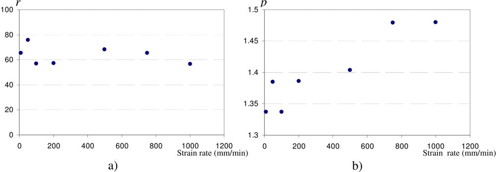
(b) Influence of the strain rate
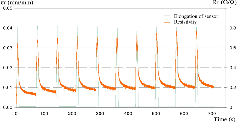
(c) Cyclic tensile tests
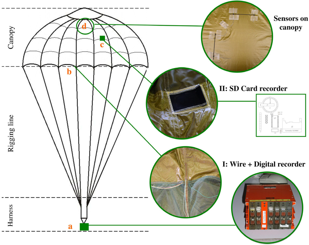
3.4. Instrumentation of parachute canopy
4. Results and Discussion
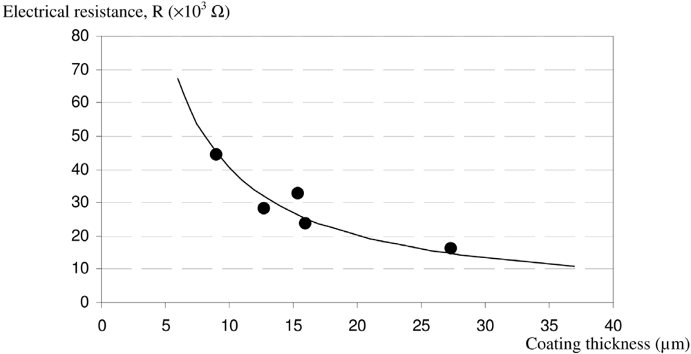
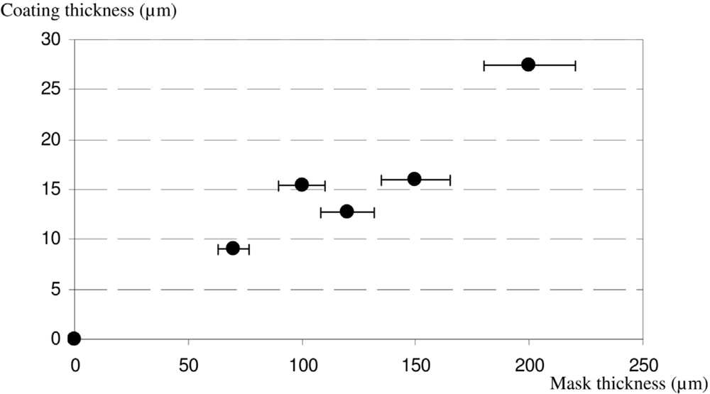
4.1. Thickness of coating
4.2. Effect of coating thickness on sensor electrical behaviour
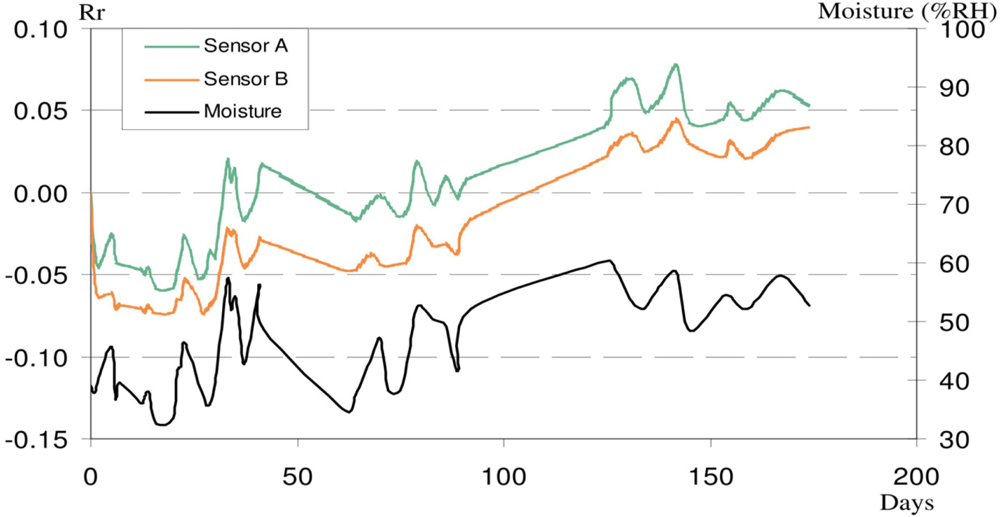
(a) Aging effect on sensor resistance
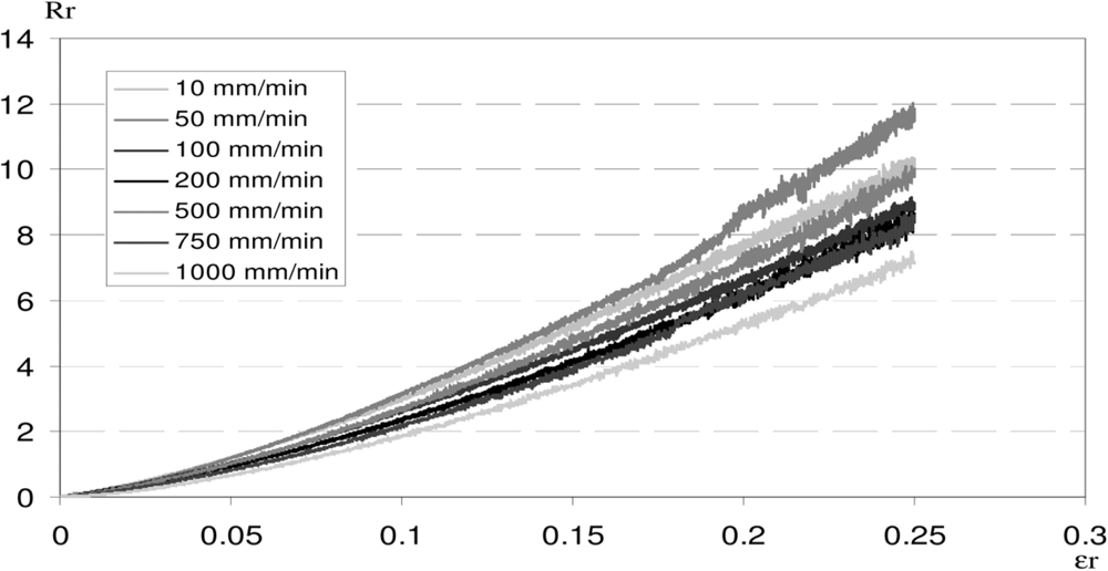
(b) Strain rate effect on sensor accuracy
(c) Effect of cyclic elongation on sensor accuracy
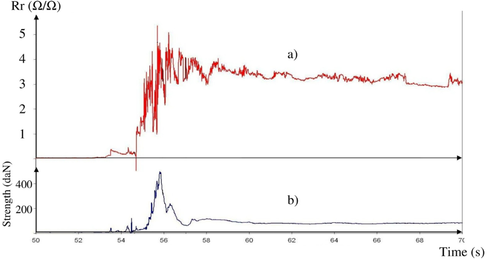
4.3. Inflation phase measurement
5. Conclusions
Acknowledgments
References and Notes
- Heinrich, HG; Noreen, RA. Stress measurements on inflated model parachutes. Proceedings of the AIAA 4th Aerodynamic Deceleration Systems Conference, Palm Springs, CA, USA, May 21–23, 1973.
- Heinrich, HG; Saari, DP. Exploratory parachute canopy stress measurements during inflation and at steady state. Proceedings of the AIAA 5th Aerodynamic Deceleration Systems Conference, Albuquerque, NM, USA, November 17–19, 1975.
- El-Sherif, MA. Smart composite with embedded sensors for in situ monitoring and diagnostic systems. Mater. Technol 1994, 9, 141–144. [Google Scholar]
- El-Sherif, MA; Fidanboylu, K; El-Sherif, D; Gafsi, R; Yuan, J; Richards, K; Lee, K. A novel fiber optic system for measuring the dynamic structural behavior of parachutes. J. Int. Mat. Syst. Struct 2000, 11, 351–359. [Google Scholar]
- Du, W; Tao, XM; Tam, HY; Choy, CL. Fundamentals and application of optical fiber Bragg grating sensors to textile structural composites. Compos. Struct 1998, 42, 217–229. [Google Scholar]
- Lorussi, F; Scilingo, EP; Tesconi, M; Tognetti, A; DeRossi, D. Strain sensing fabrics for hand posture and gesture monitoring. IEEE Trans. Inform. Technol. Biomed 2005, 9, 372–381. [Google Scholar]
- Flandin, L; Chang, A; Nazarenko, A; Hiltner, A; Bear, E. Effect of strain on the properties of an ethylene-octene elastomer with conductive carbon filler. J. Appl. Polym. Sci 2000, 76, 894–905. [Google Scholar]
- Knite, M; Teteris, V; Kiploka, A; Kaupuzs, J. Polyisoprene-carbon black nanocomposites as tensile strain and pressure sensor materials. Sens. Actuat. A 2004, 110, 142–149. [Google Scholar]
- Feller, JF; Linossier, I; Grohens, Y. Conductive polymer composites: Comparative study of poly(ester)-short carbon fibres and poly(epoxy)-short carbon fibres mechanical and electrical properties. Mater. Lett 2002, 57, 64–71. [Google Scholar]
- Li, C; Thostenson, ET; Chou, TW. Sensors and actuator based on carbon nanotubes and their composites: A review. Compos. Sci. Technol 2008, 68, 1227–1249. [Google Scholar]
- Barkauskas, J. Investigation of conductometric humidity sensors. Talanta 1997, 44, 1107–1112. [Google Scholar]
- Knite, M; Ozols, K; Sakale, G; Teteris, V. Polyisoprene and high structure carbon nanoparticule composite for sensing organic solvent vapours. Sens. Actuat. B 2007, 126, 209–213. [Google Scholar]
- Castro, M; Lu, J; Bruzaud, S; Kumar, B; Feller, JF. Carbon nanotubes/poly(e-caprolactone) composite vapour sensors. Carbon 2009, 47, 1930–1942. [Google Scholar]
- Boiteux, G; Mamunya, YeP; Lebedev, EV; Adamczewski, A; Boullanger, C; Cassagnau, P; Seytre, G. From conductive polymer composites with controlled morphology to smart materials. Synthet. Metal 2007, 157, 1071–1073. [Google Scholar]
- Cochrane, C; Koncar, V; Lewandowski, M; Dufour, C. Design and development of a flexible strain sensor for textile structures based on a conductive polymer composite. Sensors 2007, 7, 473–492. [Google Scholar]
- Cochrane, C. Développement d’un système de mesure d’allongement pour voilure de parachute. PhD thesis,. Université Lille Nord de France: Lille, France, 2007. [Google Scholar]
- Podhradska, S; Prokes, J; Omastova, M; Chodak, I. Stability of electrical properties of carbon black-filled rubbers. J. Appl. Polym. Sci 2009, 112, 2918–2924. [Google Scholar]
- Ali, MH; Abo-Hashem, A. Percolation concept and the electrical conductivity of carbon black-polymer composites 2: Non-crystallisable chloroprene rubber mixed with HAF carbon black. Mater. Process. Technol 1997, 68, 163–167. [Google Scholar]
- Wang, P; Ding, T. Conductivity and piezoresistivity of conductive carbon black filled polymer composite. J. Appl. Polym.Sci 2010, 116, 2035–2039. [Google Scholar]
- Pavlovsky, S; Siegmann, A. Chemical sensing materials. I. Electrically conductive SEBS copolymer systems. J. Appl. Polym. Sci 2009, 113, 3322–3329. [Google Scholar]
- Feller, JF; Linossier, I; Levesque, G. Conductive polymer composites (CPCs): Comparison of electrical properties of Poly(ethylene-co-ethyl Acrymate)-Carbon Black with Poly(butylene Terephthalate)/Poly(ethylene-co-ethylAcrylate)-Carbon Black. Polym. Ad. Technol 2002, 13, 714–724. [Google Scholar]
- Lorussi, F; Scilingo, EP; Tesconi, M; Tognetti, A; DeRossi, D. Strain sensing fabric for hand posture and gesture monitoring. IEEE Trans. Inform. Technol. Biomed 2005, 9, 372–281. [Google Scholar]
- Garrard, WL; Konicke, ML; Wu, KS; Muramoto, KK. Measured and calculated stress in a ribbon parachute canopy. Proceedings of the AIAA 8th Aerodynamic Decelerator and Balloon Technology Conference, Hyannis, MA, USA, April 2–4, 1984.
- Render, AB; Bradley, PD. Aerodynamic Decelerator and Balloon Technology Conference, 9th, Albuquerque, NM; Technical Papers (A87-13776 03-03); October 7–9, 1986,; American Institute of Aeronautics and Astronautics: New York, NY, USA, 1986; pp. 194–202. [Google Scholar]


© 2010 by the authors; licensee MDPI, Basel, Switzerland. This article is an open access article distributed under the terms and conditions of the Creative Commons Attribution license (http://creativecommons.org/licenses/by/3.0/).
Share and Cite
Cochrane, C.; Lewandowski, M.; Koncar, V. A Flexible Strain Sensor Based on a Conductive Polymer Composite for in situ Measurement of Parachute Canopy Deformation. Sensors 2010, 10, 8291-8303. https://doi.org/10.3390/s100908291
Cochrane C, Lewandowski M, Koncar V. A Flexible Strain Sensor Based on a Conductive Polymer Composite for in situ Measurement of Parachute Canopy Deformation. Sensors. 2010; 10(9):8291-8303. https://doi.org/10.3390/s100908291
Chicago/Turabian StyleCochrane, Cédric, Maryline Lewandowski, and Vladan Koncar. 2010. "A Flexible Strain Sensor Based on a Conductive Polymer Composite for in situ Measurement of Parachute Canopy Deformation" Sensors 10, no. 9: 8291-8303. https://doi.org/10.3390/s100908291