Design and Simulation of a MEMS Control Moment Gyroscope for the Sub-Kilogram Spacecraft

Abstract
:
1. Introduction
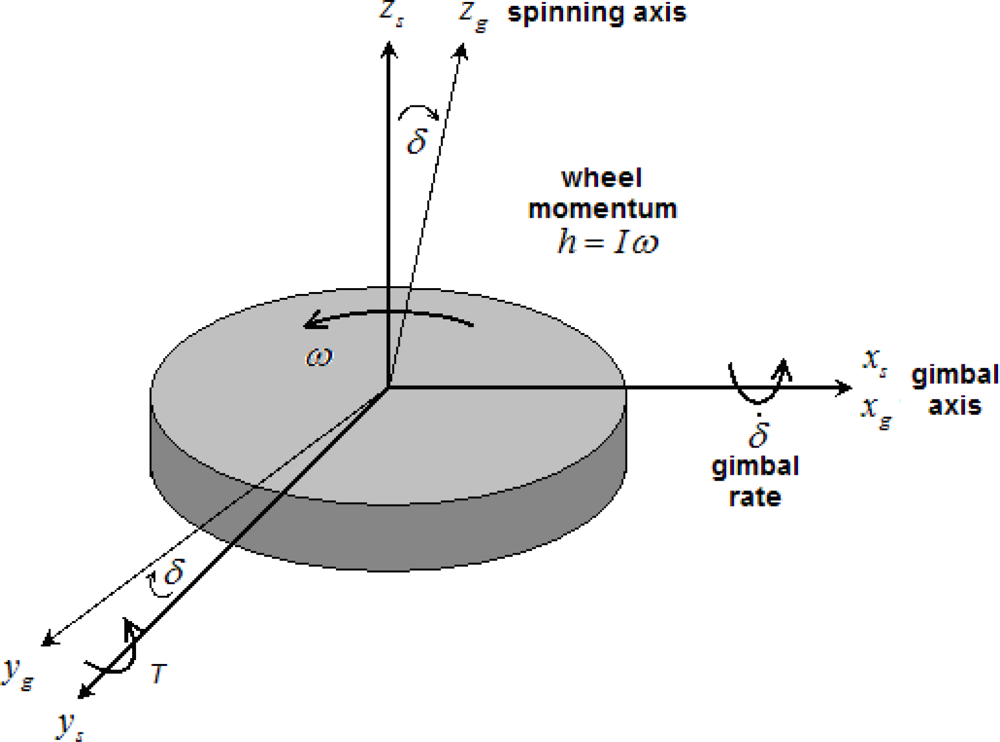
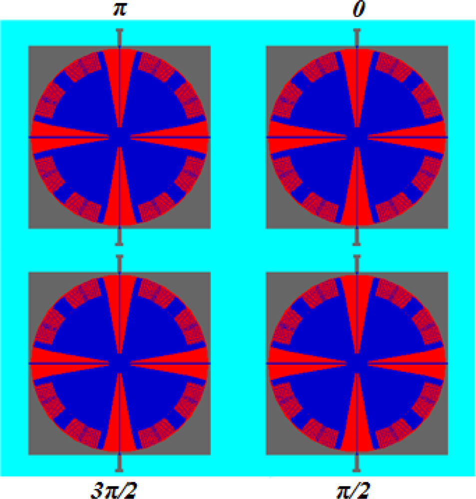
2. Working Principle of the MCMG
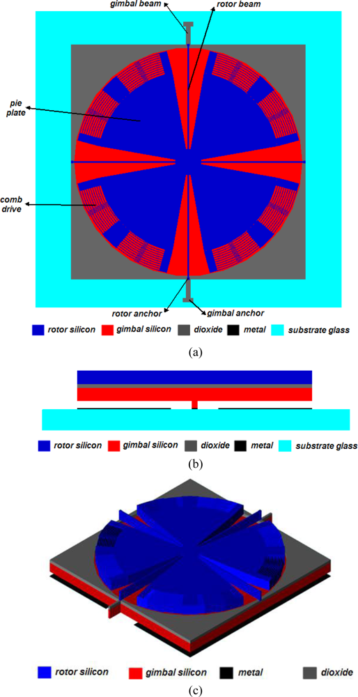
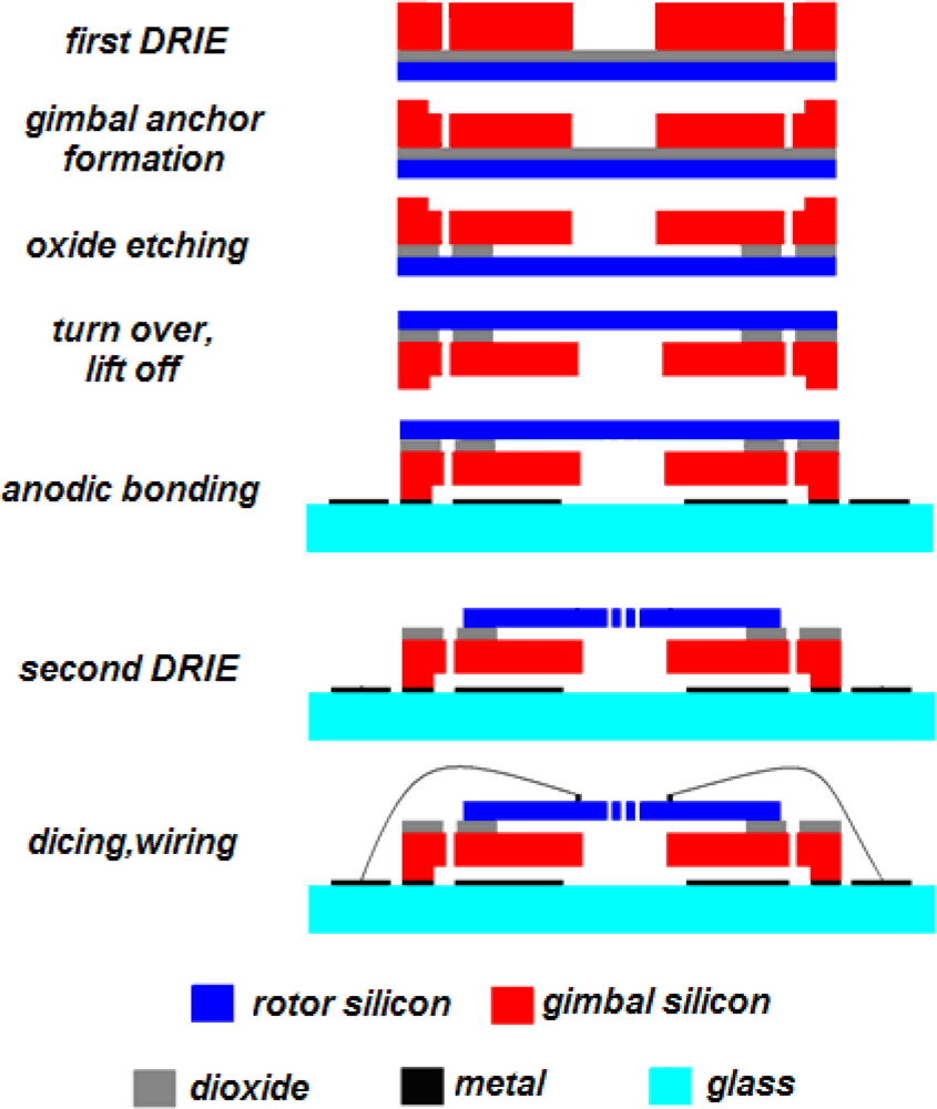
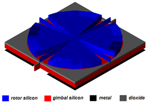
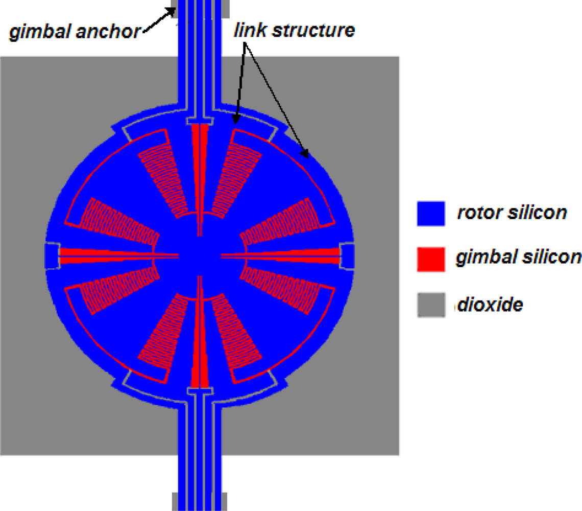
3. Structure and Process Flow for MCMG
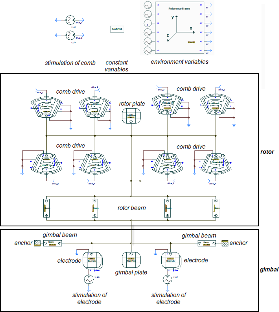
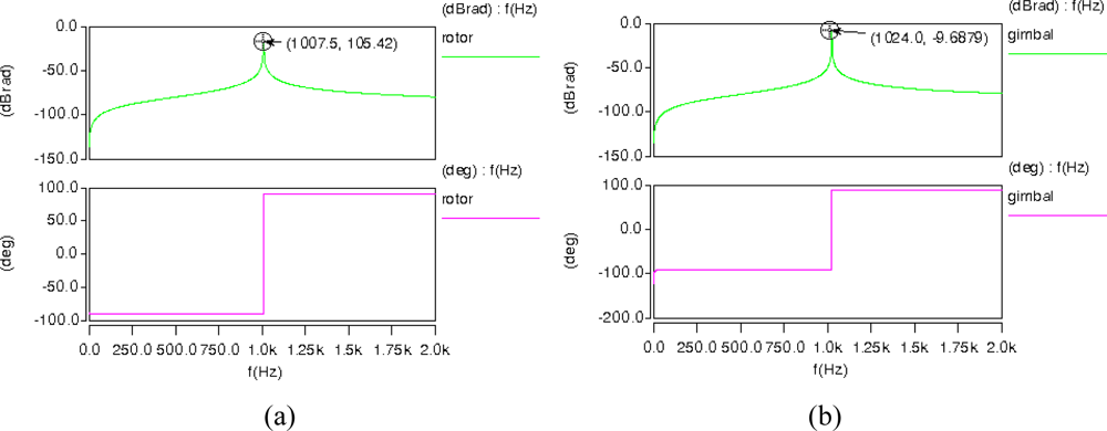
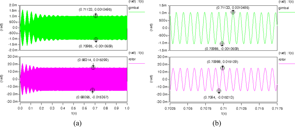
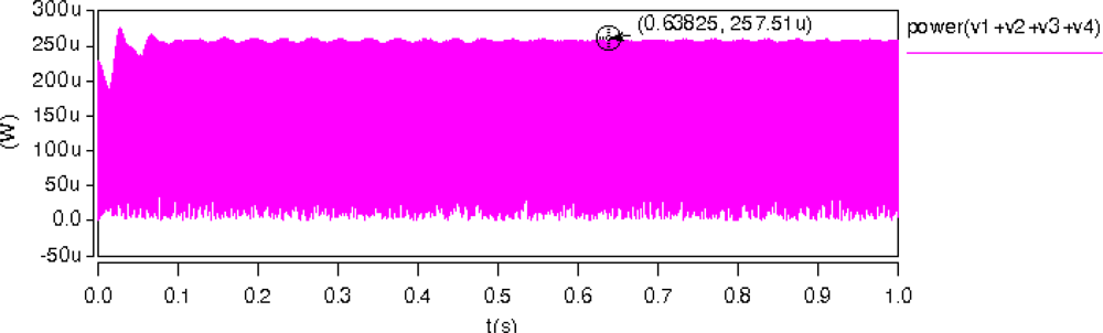
4. Behavior Simulations of MCMG
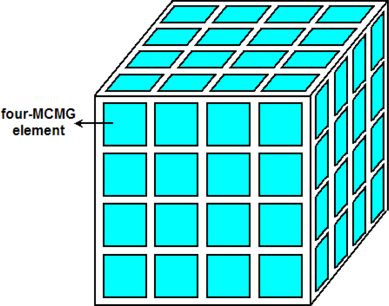
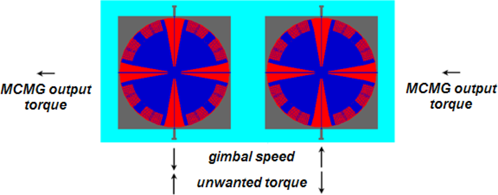
5. Application Issues of the MCMG
6. Conclusions
Acknowledgments
References and Notes
- Collins, D.; Kukkonen, C.; Venneri, S. Miniature, Low-Cost Highly Autonomous Spacecraft - A Focus for the New Millennium. Proceedings of International Astronautical Federation, Oslo, Norway, October 2–6, 1995; 10.
- Osiander, R.; Darrin, M.G.; Champion, J.L. MEMS and Microstructures in Aerospace Applications; CRC Press: Boca Raton, FL, USA, 2006; pp. 1–12. [Google Scholar]
- Rooij, N.F.; Gautsch, S.; Briand, D.; Marxer, C.; Mileti, G.; Noell, W.; Shea, H.; Staufer, U.; Schoot, B. MEMS for Space. Proceedings of Transducers 2009, Denver, CO, USA, June 21–25, 2009; pp. 17–24.
- Simon, D.H.; Land, H.B., III. Micro Pulsed Plasma Thruster Technology Development. Proceedings of AIAA 40th Joint Propulsion Conference, Fort Lauderdale, FL, USA, July 11–14, 2004; pp. 1–10.
- Wie, B.; Murphy, D.; Paluszek, M.; Thomas, S. Robust Attitude Control Systems Design for Solar Sails, Part 2: MicroPPT-based Secondary ACS. Proceedings of AIAA Guidance, Navigation, and Control Conference and Exhibit, Providence, RI, USA, August 16–19, 2004; pp. 1–16.
- Rayburn, C.; Campbell, M.; Hoskins, W.A.; Cassady, R. Development of A Micro Pulsed Plasma Thruster for the Dawgstar Nanosatellite. Proceedings of 36th AIAA/ASME/SAE/ASEE Joint Propulsion Conference and Exhibit, Huntsville, AL, USA, July 16–19, 2000; pp. 1–10.
- Schein, J.; Qi, N.; Binder, R.; Krishnan, M.; Ziemer, J.K.; Polk, J.E.; Anders, A. Inductive Energy Storage Driven Vacuum Arc Thruster. Rev. Sci. Instr 2002, 73, 925–927. [Google Scholar]
- Rysanek, F.; Hartmann, J.W.; Schein, J.; Robert, B. Micro Vacuum Arc Thruster Design for a CubeSat Class Satellite. Proceedings of 6th Annual/USU Conference on Small Satellites, Logan, UT, USA, August 12–15, 2002; pp. 1–7.
- Tajmar, M.; Scharlemann, C.; Genovese, A.; Buldrini, N.; Boss, M.; Fruholz, H.; Killinger, R. Indium FEEP Micropropulsion Subsystem for LISA Pathfinder. Proceedings of 42nd AIAA/ASME/SAE/ASEE Joint Propulsion Conference & Exhibit, Sacramento, CA, USA, July 9–12, 2006; pp. 1–9.
- Biagioni, L.; Ceccanti, F.; Saverdi, M.; Saviozzi, M.; Andrenucci, M. Qualification Status of the FEEP-150 Electric Micropropulsion Subsystem. Proceedings of 41st AIAA/ASME/SAE/ASEE Joint Propulsion Conference & Exhibit, Tucson, AZ, USA, July, 10–13, 2005; pp. 1–5.
- Phipps, C.; Luke, J.; Lippert, T.; Hauer, M.; Wokaun, A. Micropropulsion Using A Laser Ablation Jet. J. Propul. Power 2004, 20, 1000–1011. [Google Scholar]
- Wirz, R.; Polk, J.; Marrese, C.; Mueller, J. Experimental and Computational Investigation of the Performance of a Micro-Ion Thruster. Proceedings of 38th AIAA Joint Propulsion Conference, Indianapolis, IN, USA, July 7–10, 2002; pp. 1–7.
- Mukerjee, E.V.; Wallace, A.P.; Yan, K.Y.; Howard, D.W.; Smith, R.L.; Collins, S.D. Vaporizing Liquid Microthruster. Sens. Actuat. A: Phys 2000, 83, 231–236. [Google Scholar]
- Maurya, D.K.; Das, S.; Lahiri, S.K. Silicon MEMS Vaporizing Liquid Microthruster with Internal Microheater. J. Micromechanic. Microengineer 2005, 15, 966–970. [Google Scholar]
- Cardin, J.M.; Acosta, J. Design and Test of an Economical Cold Gas Propulsion System. Proceedings of 14th Annual AIAA/USU Conference on Small Satellites, Logan, UT, USA, August 21–24, 2000; pp. 1–13.
- Lewis, D.H.; Janson, S.W.; Cohen, R.B.; Antonsson, E.K. Digital Micropropulsion. Sens. Actuat. A: Phys 2000, 80, 143–154. [Google Scholar]
- Lovera, M.; Astolfi, A. Spacecraft Attitude Control Using Magnetic Actuators. Automatica 2004, 40, 1405–1414. [Google Scholar]
- Psiaki, M.L. Magnetic Torquer Attitude Control via Asymptotic Periodic Linear Quadratic Regulation. J. Guid. Control Dynam 2001, 24, 386–394. [Google Scholar]
- Wie, B. Solar Sail Attitude Control and Dynamics, Part 1. J. Guid. Control Dynam 2004, 27, 526–535. [Google Scholar]
- Wie, B. Solar Sail Attitude Control and Dynamics, Part 2. J. Guid. Control Dynam 2004, 27, 536–544. [Google Scholar]
- Singh, S. N.; Yim, W. Nonlinear Adaptive Backstepping Design for Spacecraft Attitude Control Using Solar Radiation Pressure. Proceedings of the 41st IEEE Conference on Decision and Control, Las Vegas, NV, USA, December 10–13, 2002; pp. 1239–1244.
- Lee, C.C.; Lee, A.Y. Cassini Reaction Wheel Momentum Bias Optimization Tool. Proceedings of AIAA Guidance, Navigation, and Control Conference and Exhibit, San Francisco, CA, USA, August 15–18, 2005; pp. 1–10.
- Kowalchuk, S.A. Spacecraft Attitude Sliding Mode Controller using Reaction Wheels. Proceedings of AIAA/AAS Astrodynamics Specialist Conference and Exhibit, Honolulu, HI, USA, August 18–27, 2008; pp. 1–28.
- Defendini, A.; Lagadec, K.; Guay, P.; Blais, T.; Griseri, G. Low Cost CMG-based AOCS Designs. Proceedings of 4th ESA International Conference on Spacecraft Guidance, Navigation and Control Systems, Noordwijk, The Netherlands, October 18–21, 1999; pp. 393–398.
- Roser, X.; Sghedoni, M. Control Moment Gyroscopes (CMG’s) and their Application in Future Scientific Missions. Proceedings of 3rd ESA International Conference on Spacecraft Guidance, Navigation and Control Systems, Noordwijk, The Netherlands, November 26–29, 1997; pp. 523–528.
- Lappas, V.J.; Steyn, W.H.; Underwood, C.I. Attitude Control for Small Satellites using Control Moment Gyros. Acta Astronaut 2002, 51, 101–111. [Google Scholar]
- Busseuil, J.; Llibre, M.; Roser, X. High Precision Mini-CMG’s and their Spacecraft Applications. AAS Guid. Control 1998, 98, 91–107. [Google Scholar]
- Richie, D.; Lappas, V.; Wie, B. A Practical Variable-Speed Control Moment Gyroscope Steering Law for Small Satellite Energy Storage and Attitude Control. Proceedings of AIAA/AAS Astrodynamics Specialist Conference and Exhibit, Honolulu, HI, USA, August 18–21, 2008; pp. 1–22.
- David, D.A.; Fuentes, R.J. Adaptive Attitude Control and Closed-loop Power Tracking for an Integrated Power and Attitude Control System Using Variable Speed Control Moment Gyroscopes. Proceedings of AIAA Guidance, Navigation, and Control Conference and Exhibit, San Francisco, CA, USA, August 15–18, 2005; pp. 1–23.
- Richie, D.; Tsiotras, J.; Fausz, P. Simultaneous Attitude Control and Energy Storage using VSCMGs: Theory and Simulation. Proceedings of the American Control Conference, Arlington, VA, USA, June 25–27, 2001; pp. 3973–3979.
- Schaub, H.; Vadali, S. R.; Junkins, J. L. Feedback Control Law for Variable Speed Control Moment Gyros. J. Astronaut 1998, 46, 307–328. [Google Scholar]
- Barnhart, D.J.; Vladimirova, T.; Baker, A.M.; Sweeting, M.N. A Low-cost Femtosatellite to Enable Distributed Space Missions. Acta Astronaut 2009, 64, 1123–1143. [Google Scholar]
- Barnhart, D.J.; Vladimirova, T.; Sweeting, M.N. Very-small-satellite Design for Distributed Space Missions. J. Spacecraft Rockets 2007, 44, 1294–1396. [Google Scholar]
- Caceres, M. A Sputtering Market for Nanosats and Picosats. Aerosp. Am 2006, 44, 16–18. [Google Scholar]
- Janson, S. W. Mass-producible Silicon Spacecraft for 21st Century Missions. Proceedings of AIAA Space Technology Conference and Exposition, Albuquerque, NM, USA, September 28–30, 1999; pp. 1–9.
- Lee, E. A Micro High-temperature Superconductor-magnet Flywheels with Dual Function of Energy Storage and Attitude Control. Proceedings of IEEE Sensors, Orlando, FL, USA, June 12–14, 2002; pp. 757–762.
- Peczalski, A.; Youngner, D.; French, H.; Elgersma, M.; Quenon, D.; Jacobs, J. Micro-wheels for Attitude Control and Energy Storage in Small Satellites. Proceedings of IEEE Aerospace Conference, Big Sky, MT, USA, March 10–17, 2001; pp. 2483–2492.
- Li, J.; Koh, S.; Ananthasuresh, G. K.; Ayyaswamy, P. S.; Suri, A. A Novel Attitude Control Technique for Miniature Spacecraft. Proceedings of ASME International Mechanical Engineering Congress and Exposition, New York, NY, USA, November 11–16, 2001; pp. 1–3.
- Kuo, Y. L.; Kumar, K. D.; Behdinan, K.; Fawaz, Z. Attitude Control of Miniature Spacecraft using MEMS Actuators. Proceedings of Canadian Conference on Electrical and Computer Engineering, Ottawa, ON, Canada, April 22–26, 2007; pp. 160–163.
- Reiter, J.; Bohringer, K.; Campbell, M. MEMS Control Moment Gyroscope Design and Wafer-based Spacecraft Chassis Study. Proceedings of SPIE Conference on Micromachined Devices and Components, Santa Clara, CA, USA, September 20–21, 1999; pp. 122–128.
- AndrewYeh, J.; Chen, C.N.; Lui, Y.S. Large Rotation Actuated by In-plane Rotary Comb-drives with Serpentine Spring Suspension. J. Micromechanic. Microengineer 2005, 15, 201–206. [Google Scholar]
- Seeger, J.I.; Boser, B.E. Charge Control of Parallel-plate, Electrostatic Actuators and the Tip-in Instability. J. Microelectromechanical Syst 2003, 12, 656–671. [Google Scholar]
- Nayfeh, A.H.; Younis, M.I.; Abdel-Rahman, E.M. Dynamic Pull-in Phenomenon in MEMS Resonators. Nonlinear Dynamics 2007, 48, 153–163. [Google Scholar]
- Seeger, J. I.; Boser, B. E. Parallel-plate Driven Oscillations and Resonant Pull-in. Proceedings of the Solid-State Sensor, Actuator and Microsystems Workshop, Hilton Head Island, SC, USA, June 2–6, 2002; pp. 313–316.
- Lappas, V.J.; Steyn, W.H.; Underwood, C.I. Practical Results on the Development of a Control Moment Gyro based Attitude Control System for Agile Small Satellites. Proceedings of the 16th Annual AIAA-PUSU Conference on Small Satellites, Logan, UT, USA, August 12–15, 2002; pp. 1–9.


| Parameters | Length of gimbal | Thickness of gimbal | Length of gimbal beam | Width of gimbal beam | Thickness of dioxide layer |
| Values | 9,000 μm | 299 μm | 700 μm | 101 μm | 5 μm |
| Parameter | Length of rotor beam | Width of rotor beam | Thickness of rotor | Inner diameter of pie plate | Outer diameter of pie plate |
| Values | 3800 μm | 64 μm | 80 μm | 500 μm | 3460 μm |
| Parameter | Length of pie plate | Comb finger length | Comb finger width | Comb finger gap | Comb finger overlap |
| Values | 70° | 14° | 4 μm | 3 μm | 3° |
| Rotor voltage | V1 = 25 + 25 sin(2π ft) V2 = 25 + 25 sin(2π ft + π) | ||||
| Gimbal voltage | V3 = 50 + 50 sin(2π ft) V4 = 50 + 5 sin(2π ft + π) | ||||
© 2010 by the authors; licensee MDPI, Basel, Switzerland. This article is an open-access article distributed under the terms and conditions of the Creative Commons Attribution license ( http://creativecommons.org/licenses/by/3.0/).
Share and Cite
Chang, H.; Jiao, W.; Fu, Q.; Xie, J.; Yuan, W. Design and Simulation of a MEMS Control Moment Gyroscope for the Sub-Kilogram Spacecraft. Sensors 2010, 10, 4130-4144. https://doi.org/10.3390/s100404130
Chang H, Jiao W, Fu Q, Xie J, Yuan W. Design and Simulation of a MEMS Control Moment Gyroscope for the Sub-Kilogram Spacecraft. Sensors. 2010; 10(4):4130-4144. https://doi.org/10.3390/s100404130
Chicago/Turabian StyleChang, Honglong, Wenlong Jiao, Qianyan Fu, Jianbing Xie, and Weizheng Yuan. 2010. "Design and Simulation of a MEMS Control Moment Gyroscope for the Sub-Kilogram Spacecraft" Sensors 10, no. 4: 4130-4144. https://doi.org/10.3390/s100404130