G Protein-Coupled Receptor Signaling Analysis Using Homogenous Time-Resolved Förster Resonance Energy Transfer (HTRF®) Technology

Abstract
:
1. Introduction
2. Results and Discussion
3. Experimental Section
3.1. Materials
- IP-One Tb kit–20,000 tests (Cisbio Bioassays, cat. No. 62IPAPEC; Codolet, France);
- cAMP dynamic 2 kit–20,000 tests (Cisbio Bioassays, cat. No. 62AM4PEC; Codolet, France);
- Phospho-ERK1/2 (Cellul’erk)–10,000 tests (Cisbio Bioassays, cat. No. 64ERKPEH; Codolet, France);
- Microtest™ Tissue Culture Plate, 96 Well, Clear (Becton Dickinson, cat. No. 353072; Franklin Lakes, NJ, USA);
- Small volume 384-well plate (white) (Greiner Bio-One, cat. No. GR-784075; Monroe, NC, USA);
- 384 OptiPlate (white) (PerkinElmer, cat. No. 6007290; Waltham, MA, USA);
- TopSeal-A 384, Clear Self-Adhesive Topseal for 384-well Microplates (PerkinElmer, cat. No. 6005250; Waltham, MA, USA).
3.2. Reagents
- Hank’s Balanced Salt Solution (HBSS), no Ca2+, no Mg2+, no phenol red (Invitrogen, cat. No. 14175129; Paisley, UK). Note: preferable with Ca2+ and Mg2+ when not testing a calcium-sensing receptor;
- Dulbecco’s Phosphate-Buffered Saline (DPBS), no Ca2+, no Mg2+ (Invitrogen, cat. No. 14190169; Paisley, UK). Note: preferable with Ca2+ and Mg2+ when not testing a calcium sensing-receptor;
- LiCl (Sigma-Aldrich, cat. No. 310468; St Louis, MO, USA). Note: prepare 1 M in ultra-pure H2O
- Cell Dissociation Solution (1×) Non-Enzymatic (Sigma-Aldrich, cat. No. C5914; St. Louis, MO, USA);
- Poly-d-Lysine (Sigma-Aldrich, cat. No. P-0899; St Louis, MO, USA). Note: prepare 4 mg/mL in ultra-pure H2O;
- HEPES sodium salt (Sigma-Aldrich, cat. No. H7006; St Louis, MO, USA). Note: prepare 1 M in ultra-pure H2O;
- Assay buffer (HBSS + 20 mM HEPES) adjusted to pH 7.4 using either NaOH or HCl. Note: add 1 mM CaCl2 and 1 mM MgCl2 when testing a receptor that is not activated by these salts. Bovine serum albumin (BSA) can also be added.
3.3. Equipment
- EnVision® Xcite Multilabel Plate Reader (PerkinElmer, cat. No. 2104-0020; Waltham, MA, USA) Note: With an HTRF® compatible setup (see Table 2 for an example of a setup).
3.4. Procedure
3.4.1. Cell Considerations
3.4.2. Ligand Considerations
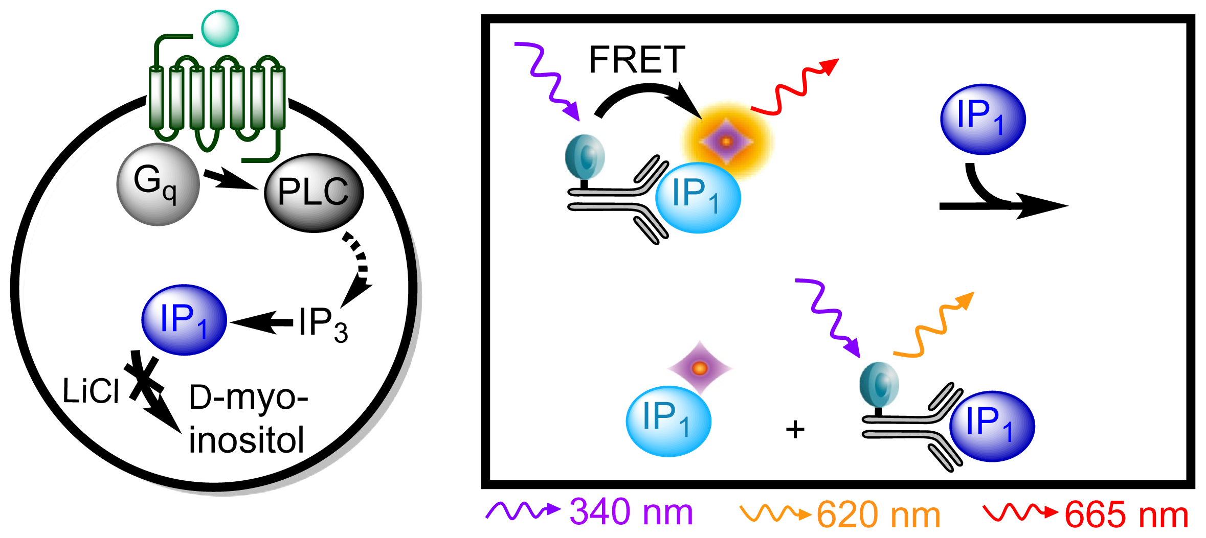
3.4.3. Protocol 1: Measurement of Gq Pathway Activation (d-myo-inositol 1-phosphate, IP1)
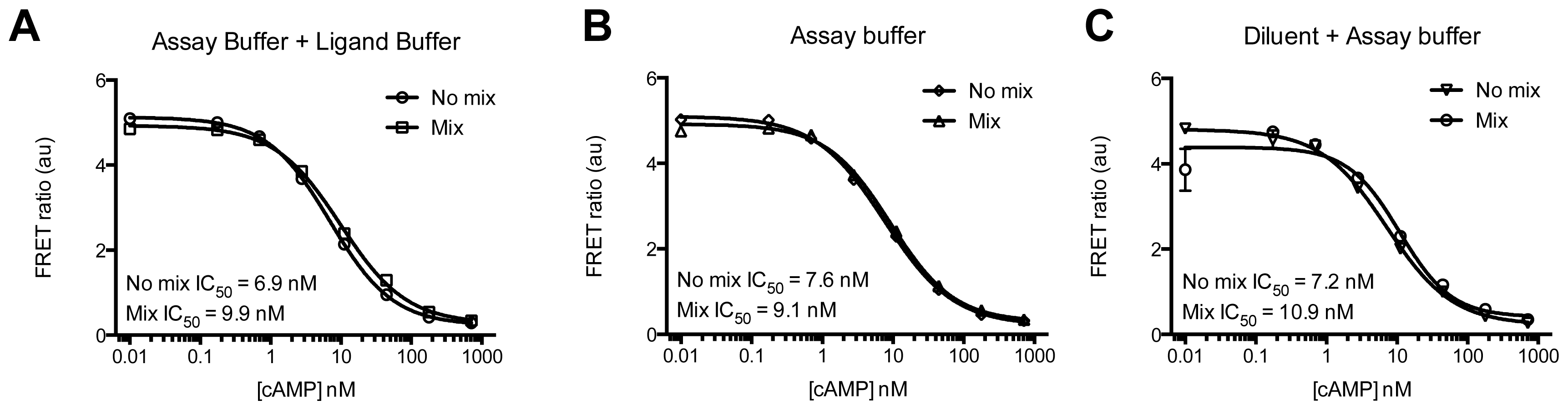
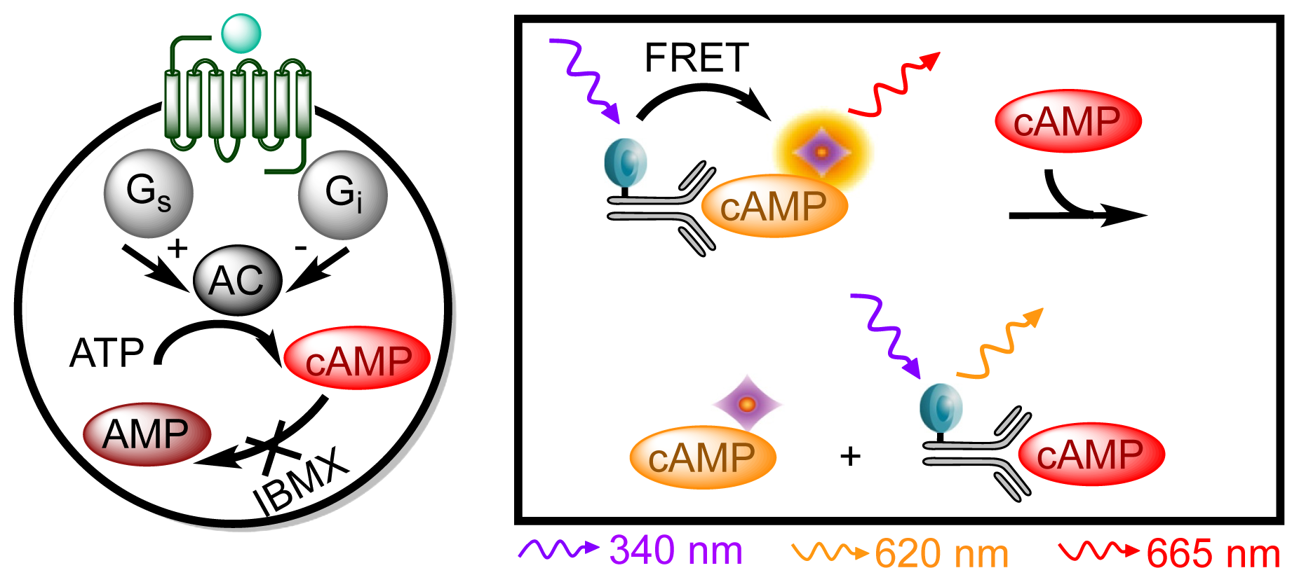
3.4.4. Protocol 2: Measurement of Gs/Gi Pathway Activation (cyclic adenosine 3′,5′-monophosphate, cAMP)
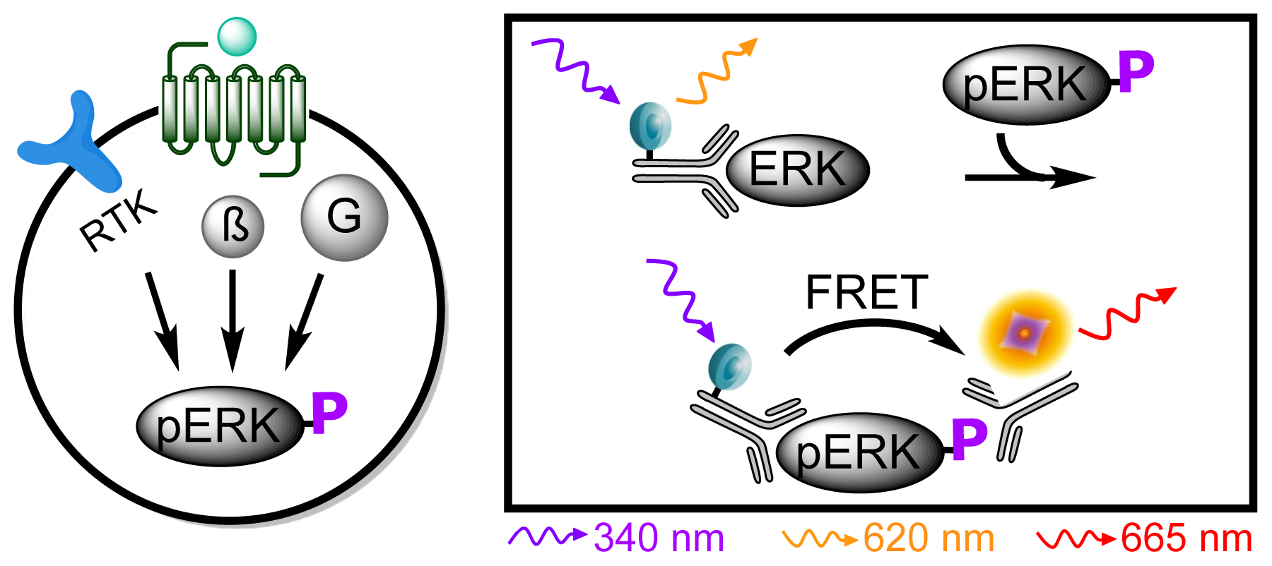
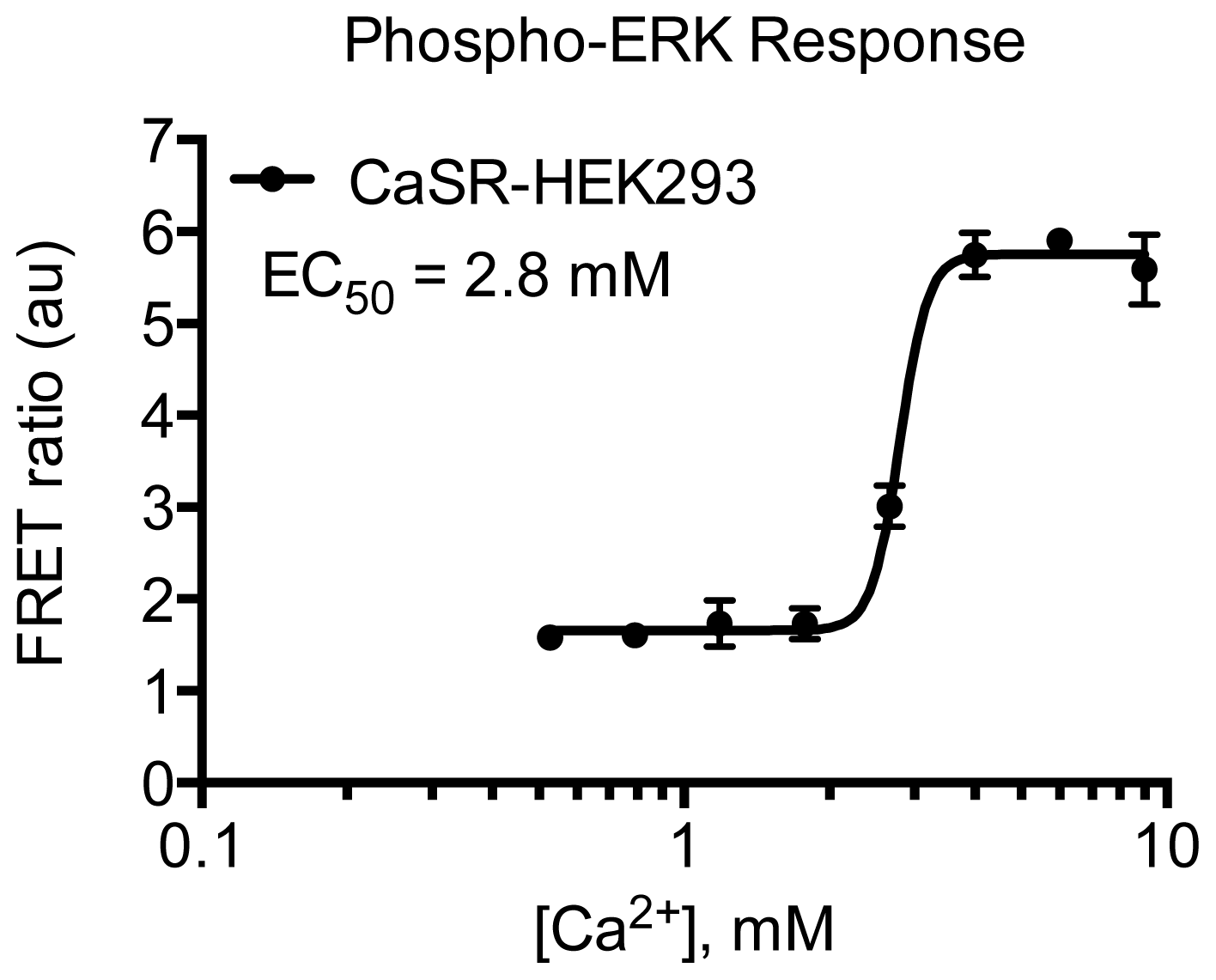
3.4.5. Protocol 3: Measurement of phosphorylated extracellular signal-regulated kinase 1 and 2 (pERK1/2)
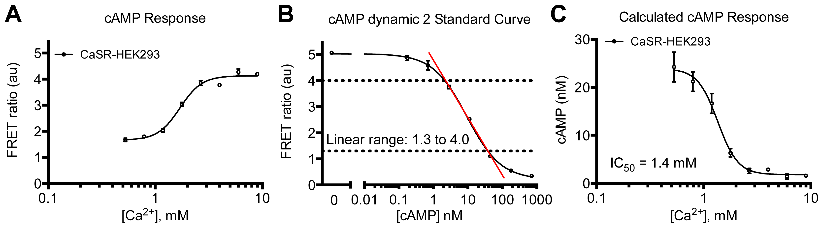
3.4.6. Data Analysis
4. Conclusions
Acknowledgments
Conflicts of Interest
References
- Chen, L.; Jin, L.; Zhou, N. An update of novel screening methods for GPCR in drug discovery. Expert Opin. Drug Discov 2012, 7, 791–806. [Google Scholar]
- Kenakin, T. Functional selectivity and biased receptor signaling. J. Pharmacol. Exp. Ther 2011, 336, 296–302. [Google Scholar]
- Fernandes, P.B. Technological advances in high-throughput screening. Curr. Opin. Chem. Biol 1998, 2, 597–603. [Google Scholar]
- Austin, C.P.; Brady, L.S.; Insel, T.R.; Collins, F.S. NIH molecular libraries initiative. Science 2004, 306, 1138–1139. [Google Scholar]
- Degorce, F.; Card, A.; Soh, S.; Trinquet, E.; Knapik, G.P.; Xie, B. HTRF: A technology tailored for drug discovery–A review of theoretical aspects and recent applications. Curr. Chem. Genomics 2009, 3, 22–32. [Google Scholar]
- Fang, Y. The development of label-free cellular assays for drug discovery. Expert Opin. Drug Discov 2011, 6, 1285–1298. [Google Scholar]
- Halai, R.; Cooper, M.A. Using label-free screening technology to improve efficiency in drug discovery. Expert Opin. Drug Discov 2012, 7, 123–131. [Google Scholar]
- Schröder, R.; Janssen, N.; Schmidt, J.; Kebig, A.; Merten, N.; Hennen, S.; Muller, A.; Blattermann, S.; Mohr-Andra, M.; Zahn, S.; et al. Deconvolution of complex G protein-coupled receptor signaling in live cells using dynamic mass redistribution measurements. Nat. Biotechnol 2010, 28, 943–949. [Google Scholar]
- Bazin, H.; Trinquet, E.; Mathis, G. Time resolved amplification of cryptate emission: A versatile technology to trace biomolecular interactions. J. Biotechnol 2002, 82, 233–250. [Google Scholar]
- Trinquet, E.; Mathis, G. Fluorescence technologies for the investigation of chemical libraries. Mol. Biosyst 2006, 2, 380–387. [Google Scholar]
- Trinquet, E.; Fink, M.; Bazin, H.; Grillet, F.; Maurin, F.; Bourrier, E.; Ansanay, H.; Leroy, C.; Michaud, A.; Durroux, T.; et al. d-myo-inositol 1-phosphate as a surrogate of d-myo-inositol 1,4,5-tris phosphate to monitor G protein-coupled receptor activation. Anal. Biochem 2006, 358, 126–135. [Google Scholar]
- Bazin, H.; Preaudat, M.; Trinquet, E.; Mathis, G. Homogeneous time resolved fluorescence resonance energy transfer using rare earth cryptates as a tool for probing molecular interactions in biology. Spectrochim. Acta A 2001, 57, 2197–2211. [Google Scholar]
- Förster, T. Energiewanderung und Fluoreszenz. Naturwissenschaften 1946, 33, 166–175. [Google Scholar]
- Vogel, S.S.; Thaler, C.; Koushik, S.V.; Fanciful, F.R.E.T. Sci. STKE 2006, 2006. [CrossRef]
- Gryczynski, Z.; Gryczynski, I.; Lakowicz, J.R. Basics of Fluorescence and FRET. In Molecular Imaging: FRET Microscopy and Spectroscopy; Periasamy, A., Day, R.N., Eds.; Oxford University Press: New York, NY, USA, 2005; pp. 40–43. [Google Scholar]
- Didier, P.; Sharma, K.K.; Mély, Y. Fluorscence Techniques to Characterise Ligand Binding to Proteins. In Biophysical Approaches Determining Ligand Binding to Biomolecualr Targets: Detection, Measurement and Modelling; Podjarny, A., Dejaegere, A., Kieffer, B., Eds.; Royal Society of Chemistry: Cambridge, UK, 2011. [Google Scholar]
- QRET Homogeneous Assay Products. Available online: http://www.bnpands.com/media/QRET.pdf (accessed on 10 January 2014).
- Harma, H.; Rozwandowicz-Jansen, A.; Martikkala, E.; Frang, H.; Hemmila, I.; Sahlberg, N.; Fey, V.; Perala, M.; Hanninen, P. A new simple cell-based homogeneous time-resolved fluorescence QRET technique for receptor-ligand interaction screening. J. Biomol. Screen 2009, 14, 936–943. [Google Scholar]
- LANCE TR-FRET Assays. Available online: http://www.perkinelmer.com/catalog/category/id/lancereagents (accessed on 10 January 2014).
- Life Technologies. Available online: http://www.lifetechnologies.com/ (accessed on 25 November 2013).
- Mathis, G. Rare earth cryptates and homogeneous fluoroimmunoassays with human sera. Clin. Chem 1993, 39, 1953–1959. [Google Scholar]
- Meares, C.; Yeh, S.; Rise, L. Diffusion enhanced lanthanide energy transfer studies of protein prosthetic groups. J. Biophys 1981, 32, 228–230. [Google Scholar]
- Selvin, P.R.; Hearst, J.E. Luminescence energy transfer using a terbium chelate: Improvements on fluorescence energy transfer. Proc. Natl. Acad. Sci. USA 1994, 91, 10024–10028. [Google Scholar]
- Rajapakse, H.E.; Gahlaut, N.; Mohandessi, S.; Yu, D.; Turner, J.R.; Miller, L.W. Time-resolved luminescence resonance energy transfer imaging of protein-protein interactions in living cells. Proc. Natl. Acad. Sci. USA 2010, 107, 13582–13587. [Google Scholar]
- Alpha, B.; Ballardini, R.; Balzani, V.; Lehn, J.-M.; Perathoner, S.; Sabbatini, N. Antenna effect in luminescent lanthanide cryptates: A photophysical study. Photochem. Photobiol 1990, 52, 299–306. [Google Scholar]
- Mathis, G. HTRF(R) technology. J. Biomol. Screen 1999, 4, 309–314. [Google Scholar]
- Trinquet, E.; Maurin, F.; Preaudat, M.; Mathis, G. Allophycocyanin 1 as a near-infrared fluorescent tracer: Isolation, characterization, chemical modification, and use in a homogeneous fluorescence resonance energy transfer system. Anal. Biochem 2001, 296, 232–244. [Google Scholar]
- Degorce, F. HTRF®: Pioneering technology for high-throughput screening. Expert Opin. Drug Discov 2006, 1, 753–764. [Google Scholar]
- Hansen, K.B.; Bräuner-Osborne, H. FLIPR assays of intracellular calcium in GPCR drug discovery. Methods Mol. Biol 2009, 552, 269–278. [Google Scholar]
- Charlton, S.J.; Vauquelin, G. Elusive equilibrium: The challenge of interpreting receptor pharmacology using calcium assays. Br. J. Pharmacol 2010, 161, 1250–1265. [Google Scholar]
- Brandish, P.E.; Hill, L.A.; Zheng, W.; Scolnick, E.M. Scintillation proximity assay of inositol phosphates in cell extracts: High-throughput measurement of G-protein-coupled receptor activation. Anal. Biochem 2003, 313, 311–318. [Google Scholar]
- Parthasarathy, L.; Vadnal, R.E.; Parthasarathy, R.; Devi, C.S. Biochemical and molecular properties of lithium-sensitive myo-inositol monophosphatase. Life Sci 1994, 54, 1127–1142. [Google Scholar]
- Trinquet, E.; Bouhelal, R.; Dietz, M. Monitoring Gq-coupled receptor response through inositol phosphate quantification with the IP-One assay. Expert Opin. Drug Discov 2011, 6, 981–994. [Google Scholar]
- Gabriel, D.; Vernier, M.; Pfeifer, M.J.; Dasen, B.; Tenaillon, L.; Bouhelal, R. High throughput screening technologies for direct cyclic AMP measurement. Assay Drug Dev. Technol 2003, 1, 291–303. [Google Scholar]
- Pierce, K.L.; Luttrell, L.M.; Lefkowitz, R.J. New mechanisms in heptahelical receptor signaling to mitogen activated protein kinase cascades. Oncogene 2001, 20, 1532–1539. [Google Scholar]
- Wetzker, R.; Bohmer, F.D. Transactivation joins multiple tracks to the ERK/MAPK cascade. Nat. Rev. Mol. Cell Biol 2003, 4, 651–657. [Google Scholar]
- Ohiro, Y.; Ueda, H.; Shibata, N.; Nagamune, T. Development of a homogeneous competitive immunoassay for phosphorylated protein antigen based on the enhanced fluorescence resonance energy transfer technology. J. Biosci. Bioeng 2010, 109, 15–19. [Google Scholar]
- Phospho-ERK (Thr202/Thr204) Cellular Assay Kit. Available online: http://www.htrf.com/phospho-erk-cellulerk (accessed on 25 November 2013).
- Thomsen, A.R.; Smajilovic, S.; Bräuner-Osborne, H. Novel strategies in drug discovery of the calcium-sensing receptor based on biased signaling. Curr. Drug Targets 2012, 13, 1324–1335. [Google Scholar]
- Brown, E.M.; El-Hajj Fuleihan, G.; Chen, C.J.; Kifor, O. A comparison of the effects of divalent and trivalent cations on parathyroid hormone release, 3′,5′-cyclic-adenosine monophosphate accumulation, and the levels of inositol phosphates in bovine parathyroid cells. Endocrinology 1990, 127, 1064–1071. [Google Scholar]
- Ferry, S.; Chatel, B.; Dodd, R.H.; Lair, C.; Gully, D.; Maffrand, J.P.; Ruat, M. Effects of divalent cations and of a calcimimetic on adrenocorticotropic hormone release in pituitary tumor cells. Biochem. Biophys. Res. Commun 1997, 238, 866–873. [Google Scholar]
- Thomsen, A.R.; Hvidtfeldt, M.; Bräuner-Osborne, H. Biased agonism of the calcium-sensing receptor. Cell Calcium 2012, 51, 107–116. [Google Scholar]
- Thomsen, A.R.; Worm, J.; Jacobsen, S.E.; Stahlhut, M.; Latta, M.; Bräuner-Osborne, H. Strontium is a biased agonist of the calcium-sensing receptor in rat medullary thyroid carcinoma 6–23 cells. J. Pharmacol. Exp. Ther 2012, 343, 638–649. [Google Scholar]
- Quinn, S.J.; Bai, M.; Brown, E.M. pH Sensing by the calcium-sensing receptor. J. Biol. Chem 2004, 279, 37241–37249. [Google Scholar]
- Quinn, S.J.; Kifor, O.; Trivedi, S.; Diaz, R.; Vassilev, P.; Brown, E. Sodium and ionic strength sensing by the calcium receptor. J. Biol. Chem 1998, 273, 19579–19586. [Google Scholar]
- Kenakin, T.; Christopoulos, A. Signalling bias in new drug discovery: Detection, quantification and therapeutic impact. Nat. Rev. Drug Discov 2013, 12, 205–216. [Google Scholar]
- Jacobsen, S.E.; Norskov-Lauritsen, L.; Thomsen, A.R.; Smajilovic, S.; Wellendorph, P.; Larsson, N.H.; Lehmann, A.; Bhatia, V.K.; Brauner-Osborne, H. Delineation of the GPRC6A receptor signaling pathways using a mammalian cell line stably expressing the receptor. J. Pharmacol. Exp. Ther 2013, 347, 298–309. [Google Scholar]
- Bergsdorf, C.; Kropp-Goerkis, C.; Kaehler, I.; Ketscher, L.; Boemer, U.; Parczyk, K.; Bader, B. A one-day, dispense-only IP-One HTRF assay for high-throughput screening of Galphaq protein-coupled receptors: Towards cells as reagents. Assay Drug Dev. Technol 2008, 6, 39–53. [Google Scholar]
- Liu, K.; Titus, S.; Southall, N.; Zhu, P.; Inglese, J.; Austin, C.P.; Zheng, W. Comparison on functional assays for Gq-coupled GPCRs by measuring inositol monophospate-1 and intracellular calcium in 1536-well plate format. Curr. Chem. Genomics 2008, 1, 70–78. [Google Scholar]
- Titus, S.; Neumann, S.; Zheng, W.; Southall, N.; Michael, S.; Klumpp, C.; Yasgar, A.; Shinn, P.; Thomas, C.J.; Inglese, J.; et al. Quantitative high-throughput screening using a live-cell cAMP assay identifies small-molecule agonists of the TSH receptor. J. Biomol. Screen 2008, 13, 120–127. [Google Scholar]
- Jia, Y. Current status of HTRF® technology in kinase assays. Expert Opin. Drug Discov 2008, 3, 1461–1474. [Google Scholar]
- Laboureau, J.; Dubertret, L.; Lebreton-de Coster, C.; Coulomb, B. ERK activation by mechanical strain is regulated by the small G proteins rac-1 and rhoA. Exp. Dermatol 2004, 13, 70–77. [Google Scholar]


| Assay | Cell amount per well (plate format) | Stimulation time (min) | Stimulation temp. (°C) | Inhibitor/activator (final concentration) |
|---|---|---|---|---|
| IP1 | 104 (384; suspension) | 60 | 37 | 20 mM LiCl |
| cAMP | 2 × 10⁴ (384; suspension) | 30 | Room temp. | 500 nM IBMX + 5 μM forskolin |
| pERK1/2 | 5 × 10⁴ (96;adherent, 24 h before) | 15 | Room temp. | - |
| System | Setting |
|---|---|
| Excitation | Top |
| Emission | Top |
| Second emission | Top |
| Excitation filter | UV (TRF) 340 (CWL = 340 nm, BW = 60 nm) |
| Emission filter | APC 665 (CWL = 665 nm, BW = 7.5 nm) |
| Second emission filter | Europium 615 (CWL = 615 nm, BW = 8.5 nm) |
| Measurement height | 10.2 mm |
| Cycle (time between flashes) | 2000 μs |
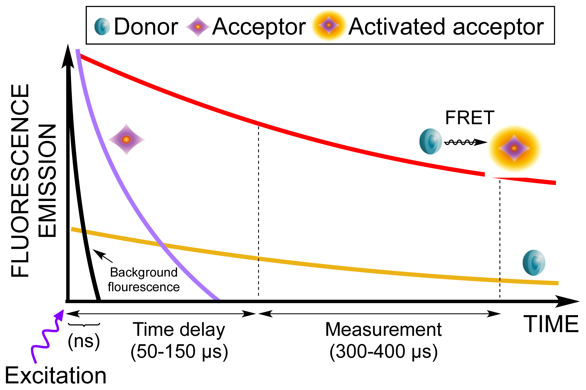
| Delay | 150 μs |
| Number of flashes | 100 |
| Number of flashes for 2nd detector | 20 |
| Number of sequence windows | 1 |
| Total time of windows (measurement time) | 300 μs |
© 2014 by the authors; licensee MDPI, Basel, Switzerland This article is an open access article distributed under the terms and conditions of the Creative Commons Attribution license (http://creativecommons.org/licenses/by/3.0/).
Share and Cite
Nørskov-Lauritsen, L.; Thomsen, A.R.B.; Bräuner-Osborne, H. G Protein-Coupled Receptor Signaling Analysis Using Homogenous Time-Resolved Förster Resonance Energy Transfer (HTRF®) Technology. Int. J. Mol. Sci. 2014, 15, 2554-2572. https://doi.org/10.3390/ijms15022554
Nørskov-Lauritsen L, Thomsen ARB, Bräuner-Osborne H. G Protein-Coupled Receptor Signaling Analysis Using Homogenous Time-Resolved Förster Resonance Energy Transfer (HTRF®) Technology. International Journal of Molecular Sciences. 2014; 15(2):2554-2572. https://doi.org/10.3390/ijms15022554
Chicago/Turabian StyleNørskov-Lauritsen, Lenea, Alex Rojas Bie Thomsen, and Hans Bräuner-Osborne. 2014. "G Protein-Coupled Receptor Signaling Analysis Using Homogenous Time-Resolved Förster Resonance Energy Transfer (HTRF®) Technology" International Journal of Molecular Sciences 15, no. 2: 2554-2572. https://doi.org/10.3390/ijms15022554