Article

Nonlocal Buckling Analysis of Composite Curved Beams Reinforced with Functionally Graded Carbon Nanotubes

by
Behrouz Karami
1,*,
Maziar Janghorban
1,
Davood Shahsavari
1,
Rossana Dimitri
2 and
Francesco Tornabene
2,*
1
Department of Mechanical Engineering, Marvdasht Branch, Islamic Azad University, Marvdasht 73711-13119, Iran
2
Department of Innovation Engineering, University of Salento, 73100 Lecce, Italy
*
Authors to whom correspondence should be addressed.
Molecules 2019, 24(15), 2750; https://doi.org/10.3390/molecules24152750
Submission received: 7 July 2019 / Revised: 26 July 2019 / Accepted: 28 July 2019 / Published: 29 July 2019
(This article belongs to the Section Materials Chemistry)

Abstract

:
This work deals with the size-dependent buckling response of functionally graded carbon nanotube-reinforced composite (FG-CNTRC) (FG-CNTRC) curved beams based on a higher-order shear deformation beam theory in conjunction with the Eringen Nonlocal Differential Model (ENDM). The material properties were estimated using the rule of mixtures. The Hamiltonian principle was employed to derive the governing equations of the problem which were, in turn, solved via the Galerkin method to obtain the critical buckling load of FG-CNTRC curved beams with different boundary conditions. A detailed parametric study was carried out to investigate the influence of the nonlocal parameter, CNTs volume fraction, opening angle, slenderness ratio, and boundary conditions on the mechanical buckling characteristics of FG-CNTRC curved beams. A large parametric investigation was performed on the mechanical buckling behavior of FG-CNTRC curved beams, which included different CNT distribution schemes, as useful for design purposes in many practical engineering applications.

1. Introduction

The reinforcement of nanocomposites with the introduction of carbon nanotubes (CNTs) as filler beside a polymeric matrix is well known to improve the potential applications of a structure in some fields of mechanics and electronics. Indeed, in recent decades, CNTs reinforced nanocomposites have been increasingly studied in the scientific community because of their remarkable properties [1,2,3,4,5,6,7,8,9]. CNTs are made of graphene sheets as it is the thinnest material in the world. Therefore, the use of CNTs with very small dimensions cannot disregard the possibility of size-dependent behavior of materials, especially at a nanoscale. This represents a challenging aspect to consider during the evaluation of the structural behavior of nanomaterials. To overcome this issue, a large variety of methods and strategies have been proposed in the literature, including laboratory tests, molecular dynamics-based simulations, and non-classical mathematical methods [10,11,12,13,14,15,16,17,18,19]. Among them, experimental tests and molecular dynamics simulations, however, are typically expensive and time-consuming, which has led to find an attention to use theoretical and numerical models for approaching similar problems. In this framework, Eringen [20,21] proposed a size-dependent model in which the size-dependent behavior is considered by introducing one small-scale nonlocal parameter. However, this approach considers only the softening enhancement of the size-dependence in nanostructured systems. Bouafia et al. [22] analyzed the bending and vibration response of FG nanobeams via a nonlocal quasi-3D theory. Shahsavari et al. [23] studied the forced vibration of viscoelastic graphene sheet under the moving load using a nonlocal refined plate theory. Ganapathi et al. [24] studied the vibrations of curved nanobeams via a nonlocal higher-order theory based on a finite element approach. For the first time, a guided wave propagation analysis of porous nanoplates was performed by Karami et al. [25] using the differential constitutive nonlocal model of Eringen in conjunction with the first-order shear deformation theory. The elastic stability response of curved nanobeams was analyzed by Polit et al. [26] using a nonlocal higher-order shear deformation theory employed in a finite element context. A further application of the nonlocal higher-order theory can be found in the work of Ganapathi and Polit [27] for the numerical study of the bending and buckling response of curved nanobeams, including the thickness stretching effect. For the first time, the shear buckling analysis of porous nanoplates was presented by Shahsavari et al. [28] using a nonlocal quasi-3D plate theory. A different single variable shear deformable nonlocal theory was applied instead, by Shimpi et al. [29], for the static analysis of rectangular micro/nanobeams subjected to a transverse loading, whereas a comprehensive study of the CNTs reinforced composite plates was presented by Karami et al. [30] by applying a nonlocal second-order shear deformable theory.
In a context where curved structures like beams or tubes play a remarkable role in many nanotechnology applications because of their engineering properties (i.e., high strength/stiffness to weight ratios), various size-dependent investigations of reinforced curved beams, tubes, and shells have been carried out in literature [31,32,33,34,35,36,37,38,39,40,41], including different theoretical or computational strategies.
In the current work, the buckling response of CNT reinforced composite curved beams was investigated through the constitutive equations of the nonlocal elasticity, while originally employing the Galerkin method. A continuum model of the nanobeam was also considered based on a higher-order refined theory of beams, which included the shear deformation effects without any proper introduction of shear correction factors. The nonlocal governing equations of the CNT reinforced curved size-dependent beams are here described by means of the Hamiltonian principle, which has been written in a variational form, and they are solved numerically for simply-supported and clamped boundary conditions. After evaluating the accuracy of the proposed method using the available literature, we represent the main results based on a large parametric investigation aimed to studying the influence of boundary conditions, opening angles, CNT distribution patterns, volume fractions, and nonlocal parameters on the critical mechanical buckling force, which is useful for the structural analysis and design of composite curved nanostructures.
The paper is organized as follows. Following the introduction section, we describe the basic fundamentals of the size-dependent problem in Section 2, while the considered solution strategy is presented in Section 3. Afterwards, Section 4 presents the numerical results of a large parametric investigation, useful for design purposes for many engineering applications. Finally, concluding remarks are summarized in Section 5.

2. Size-Dependent Problem

2.1. Basic Fundamentals

In this section, we consider the nonlocal model of Eringen [20], which is based on the following stress-strain relations:
τ i j = V α ( | x x | ) , τ σ i j ( x ) d ( V )
σ i j and τ i j being the local and nonlocal stress tensors, together with the following differential equations typically defined for a size-dependent behavior of nanostructure systems:
( 1 ( e 0 a ) 2 2 ) σ i j = C i j k l ε k l
where 2 is the Laplacian operator.
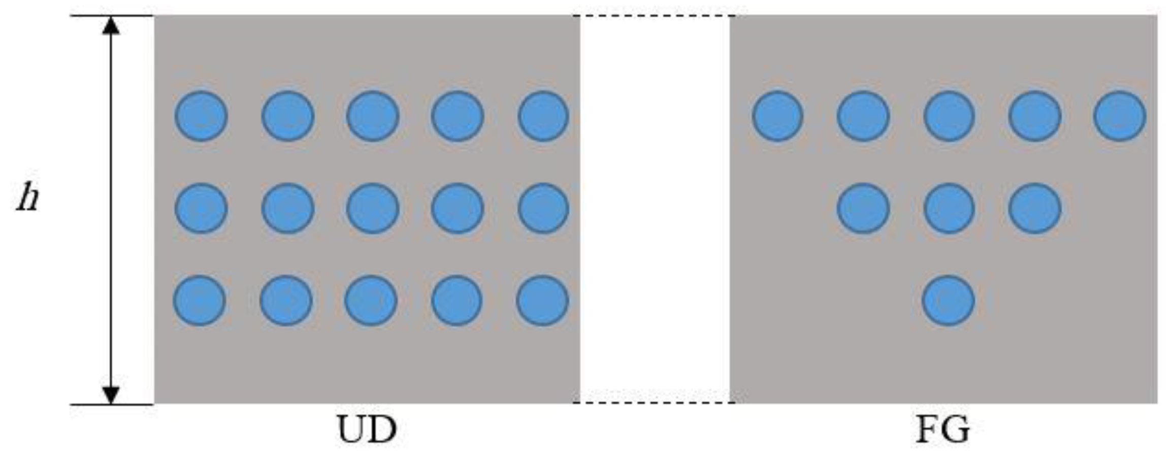
Let us consider a CNTRC curved beam with length L and thickness h, as shown in Figure 1. Two different distributions of CNTs are here considered, namely a uniform distribution (UD) and a non-uniform functionally graded (FG) distribution, along the thickness direction of the curved beam (Figure 2), whereby the CNTs are added as filler beside the matrix for the reinforcement purposes. Hence, the effective material properties of CNTRC curved beams are defined, based on the Mori–Tanaka micromechanical scheme and the rule of mixture, as follows [42]:
E 11 = η 1 V C N T E 11 C N T + V m E m
η 2 E 2 = V C N T E 22 C N T + V m E m
η 3 G 12 = V C N T G 12 C N T + V m G m
In the previous relations, E 12 C N T , E 22 C N T G 12 C N T are the Young moduli and shear modulus of CNT; Em, Gm refer to the mechanical properties for the matrix; and V C N T and V m denote the volume fractions of the CNT and matrix, respectively, such that:
V C N T + V m = 1
The CNTs efficiency parameters η j in Equations (3)–(5) must be determined before computing the effective material properties of the structure. Thus, we estimate the CNT efficiency parameters η 1 and η 2 by comparing the Young’s moduli E 11 C N T and E 22 C N T for the CNTRCs, as obtained by the rule of mixtures, with those given by Han and Elliott [43]. In Table 1, the mechanical properties with a clear good agreement between the molecular dynamics and the rule of mixture are summarized after a proper selection of η 1 and η 2 . Moreover, the effective Poisson’s ratio and mass density are expressed as”
ν 12 = V C N T * ν 12 C N T + V m ν m
ρ = V C N T ρ C N T + V m ρ m
where ν 12 C N T , ρ C N T stand for the Poisson’s ratio and mass density of the CNT; and ν 12 C N T , ρ C N T refer to the Poisson’s ratio and mass density of the matrix, respectively. The selected distribution schemes for CNTs along the thickness direction can be expressed analytically as [42]:
V C N T = { V C N T ( UD ) ( 1 + 2 z h ) V C N T ( FG )
where:
V C N T = w C N T w C N T + ( ρ C N T / ρ m ) ( ρ C N T / ρ m ) w C N T
and w C N T is the mass fraction of the CNTs.
In what follows, we include the interactions among the CNTs and the matrix, while ignoring the effects of strains at general points of the nanocomposite on the stresses at a reference point. Thus, to avoid any possible inaccuracy related to the above-mentioned approximation, it is referred to the presence of nonlocal parameters as required by the Eringen Nonlocal Differential Model (ENDM) to predict the size-dependent behavior of nanostructure systems.

2.2. Displacement Field and Strain

According to the refined beam theory, the curved beam is modeled as a continuum model with its displacement field defined as [44]:
u θ ( θ , r , t ) = ( 1 + z R ) u ( θ , t ) + z R ( w b ( θ , t ) θ ) + f ( z ) R ( w s ( θ , t ) θ )
w r ( θ , r , t ) = w b ( θ , t ) w s ( θ , t )
where u is the tangential mid-plane displacement, wb and ws are the bending and shear components of the radial displacement, respectively; and f (z) is the shape function defined as:
f ( z ) = h π ( sinh [ π z h ] z ) ( cosh [ π 2 ] ) 1
It is interesting to note that the shape function in Equation (13) satisfies the stress-free boundary conditions on the top and bottom surfaces of the beam without using any shear correction factor. The non-zero strain field related to the displacement components is:
ε x = ε x 0 + z k x b + f ( z ) k x s ,    γ x z = g ( z ) ( γ x z 0 )
where:
ε x 0 = 1 R ( w b w s + u θ ) , k x b = 1 R 2 ( u θ + 2 w b θ 2 ) , k x s = f ( z ) R 2 ( 2 w s θ 2 ) , γ x z 0 = w s R θ
and g ( z ) = 1 f ( z ) .

2.3. Governing Equations

The equations of motion for the stability of composite curved beams can be derived from the Hamilton’s principle:
0 t δ ( U + V ) d t = 0
where U and V refer to the strain energy and work done by external forces, respectively. The variational form of the strain energy is expressed as:
δ U = V σ i j δ ε i j d V = V ( σ x x δ ε x x + τ x z δ γ x x ) d V = 0 L ( N ( δ w b R δ w s R + δ u R θ ) M b R 2 ( δ u θ + 2 δ w b θ 2 ) M s R 2 2 δ w s θ 2 + Q R δ w s θ ) R d θ
where:
( N , M b , M s ) = h 2 h 2 ( 1 , z , f ( z ) ) σ x x d z ,    Q = h 2 h 2 g ( z ) τ x z d z
Accordingly, the work done by the applied forces takes the following form:
δ V = 0 L N b R 2 ( ( w b + w s ) θ δ ( w b + w s ) θ ) R d θ
Nb is the applied tangential force here. By substituting Equations (17), (19) into Equation (16) and integrating by parts with respect to space and time variables, the equations of motion in terms of the displacement components of the curved beam can be obtained as:
N θ 1 R M b θ = 0
2 M b R θ 2 N N b R 2 ( w b + w s ) θ 2 = 0
2 M s R θ 2 N + Q θ N b R 2 ( w b + w s ) θ 2 = 0
Now, the constitutive equations of the nonlocal refined curved beam are introduced as follows:
σ x x μ 2 σ x x θ 2 = E ε x x
τ x z μ 2 τ x z θ 2 = G γ x z
where µ = (e0a)2. By the combination of Equations (2)–(21), (23), (24), we get to the following relations for the curved beam:
N μ 2 N R 2 θ 2 = ( A R ( w b w s + u θ ) + B R 2 ( u θ + 2 w b θ 2 ) + B s R 2 2 w s θ 2 )
M b μ 2 M b R 2 θ 2 = ( B R ( w b w s + u θ ) + D R 2 ( u θ + 2 w b θ 2 ) + D s R 2 2 w s θ 2 )
M s μ 2 M s R 2 θ 2 = ( B s R ( w b w s + u θ ) + D s R 2 ( u θ + 2 w b θ 2 ) + H s R 2 2 w s θ 2 )
Q μ 2 Q R 2 θ 2 = ( A s R w s θ )
where:
( A , B , B s , D , D s , H s ) = h 2 h 2 E ( 1 , z , f ( z ) , z 2 , z f ( z ) , f 2 ( z ) ) d z
A s = h 2 h 2 g 2 ( z ) G d z
Upon rearrangement, we get to the following governing equations of the beam in terms of displacement components:
A R ( w b θ w s θ + 2 u θ 2 ) + B R 2 ( w b θ w s θ + 2 2 u θ 2 + 3 w b θ 3 ) + B s R 2 3 w s θ 3 + D R 3 ( 2 u θ 2 + 3 w b θ 3 ) + D s R 3 3 w s θ 3 = 0
B R 2 ( 2 w b θ 2 2 w s θ 2 + 3 u θ 3 ) + D R 3 ( 3 u θ 3 + 4 w b θ 4 ) + D s R 3 4 w s θ 4 A R ( w b w s + u θ ) B R 2 ( 2 w b θ 2 + u θ ) B s R 2 2 w s θ 2 N b R 2 ( w b + w s ) θ 2 + μ R 2 ( N b R 4 ( w b + w s ) θ 4 ) = 0
B s R 2 ( 2 w b θ 2 2 w s θ 2 + 3 u θ 3 ) + D s R 3 ( 3 u θ 3 + 4 w b θ 4 ) + H s R 3 4 w s θ 4 A R ( w b w s + u θ ) B R 2 ( 2 w b θ 2 + u θ ) B s R 2 2 w s θ 2 A s R 2 2 w s θ 2 N b R 2 ( w b + w s ) θ 2 + μ R 2 ( N b R 4 ( w b + w s ) θ 4 ) = 0

3. Solution Methodology

The Galerkin method is here employed to solve the equations of motion for functionally graded carbon nanotube-reinforced composite (FG-CNTRC) curved beams with simply-simply (S-S) supports, clamped-simply (C-S) supports, and clamped-clamped (C-C) supports, respectively:
Simply-supports (S):
wb = ws = M = 0 at x = 0, L
Clamped-supports (C):
u = wb = ws = 0 at x = 0, L
Assuming the following expansion for the displacement field:
u ( θ ) = n = 1 U n F m ( θ ) θ
w b ( θ ) = n = 1 W b n F m ( θ )
w s ( θ ) = n = 1 W s n F m ( θ )
and by introducing the Equations (34)–(36) into Equations (31)–(33), the following set of relations can be obtained:
K { U n W b n W s n } = 0
in which K represents the stiffness matrix. The admissible function Fm is selected in the following as the beam eigenfunction, i.e.,
  • S-S: F m = sin ( n π α θ )
  • C-S: F m = sin ( n π α θ ) [ cos ( n π α θ ) 1 ]
  • C-C: sin 2 ( n π α θ )
To obtain the critical buckling force, we must enforce the determinant of the stiffness matrix equal to zero. This parameter will be quantified in nondimensional form in the next parametric analysis, namely:
N c r = N b R 2 E M h 3

4. Numerical Results

The procedure proposed in the previous section is here applied to study the size-dependent buckling behavior of FG-CNTRC curved beams. The higher-order shear deformation beam theory is also applied to model the nanobeam, whereby the size-dependent effect is considered by means of the application of the Eringen nonlocal differential model. Thus, the buckling phenomena of the nanostructure are solved mathematically via the Galerkin method for different boundary conditions. The parametric study presented in this work analyzes the sensitivity of the size-dependent buckling response of FG-CNTRC curved beams reinforced with CNTs to some mechanical parameters (i.e., the nonlocal parameter and the nanotube volume fraction), as well as to some geometrical parameters, (namely, the opening angle, slenderness ratio, and the CNT distribution schemes). The preliminary focus of the investigation was on the accuracy of the proposed method to compute the critical buckling load, whose results are summarized in Table 2 in nondimensional form for an S-S beam, while varying the nonlocal parameter µ. Based on a comparative evaluation between our predictions and those obtained by Reddy [45], Aydogdu [46], and Eltaher [47], a very good match was observed, which confirms the accuracy of the proposed formulation for similar problems.
Next, we discuss about the size-dependence of the buckling load for FG-CNTRC curved beams with different boundary conditions (see Table 3, Table 4, Table 5, Table 6, Table 7, Table 8, Table 9, Table 10 and Table 11 and Figure 3, Figure 4 and Figure 5), together with results for UD-CNTRC counterparts, for a direct comparison. Unless otherwise stated before, the length of the curved beam is fixed at L = 20, whereby a Poly{(m-phenylenevinylene)-co-[(2,5-dioctoxy-p-phenylene) vinylene]} is selected as matrix (henceforth labeled as PmPV), with Poisson’s ratio ν m = 0.34 , elastic modulus E m = 2.1 GPa , and temperature T = 300 K. As reinforcement phase, instead, we select an armchair (10, 10) SWCNTs, with elastic moduli E 11 C N T = 5.6466 TPa , E 22 C N T = 7.080 TPa , and Poisson’s ratio ν C N T = 0.175 .
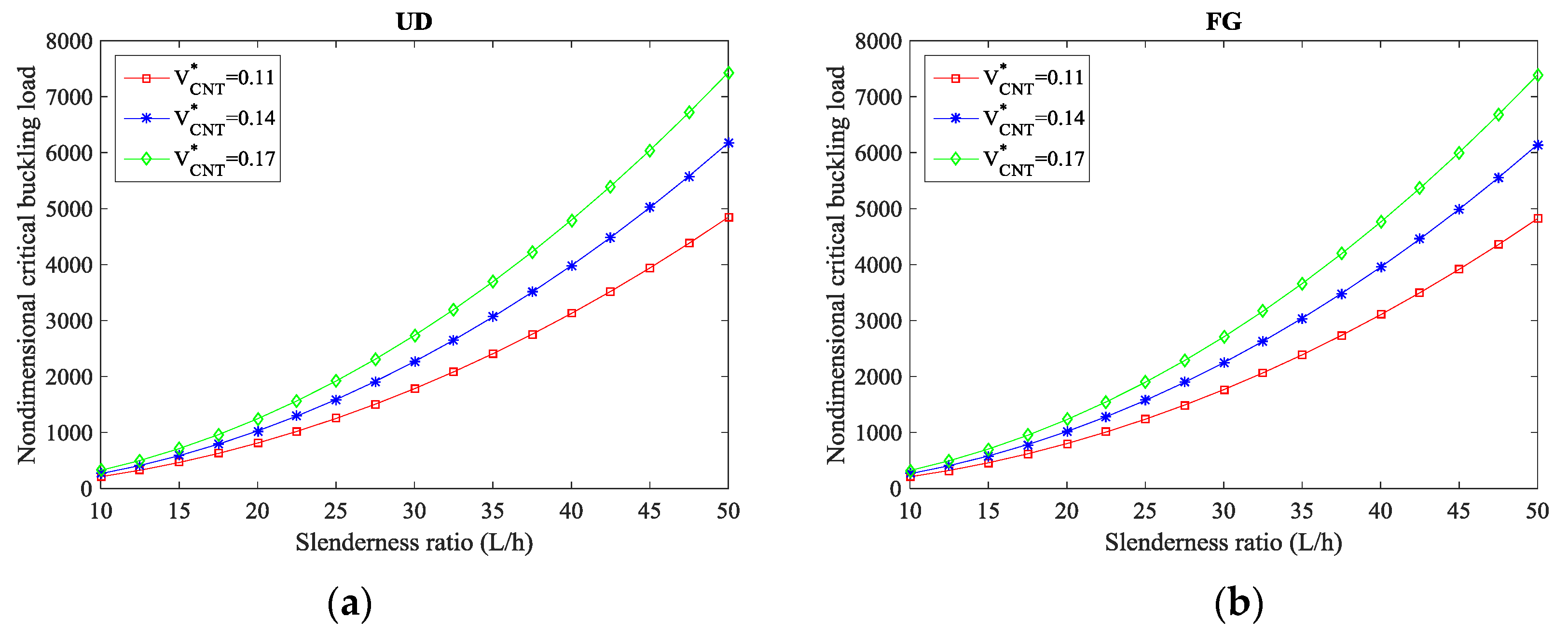
More specifically, Table 3, Table 4 and Table 5 evaluate the effect of the volume fraction and distribution patterns of CNTs on the nondimensional critical buckling load of the composite curved beams for S-S, C-S, and C-C CNTRC curved beams, respectively, while L/h = 1 and α = π/3 are considered. By exploiting the numerical results in Table 3, Table 4 and Table 5 comparatively, it is worth noting that clamped nanostructures yield the maximum buckling load, while S-S beams get the lowest buckling values. Moreover, an increment in the volume fraction of CNTs V C N T * significantly raises the buckling load of both UD- and FG-CNTRCs, with its behavior also affected by the nonlocality µ. More specifically, a rise in nonlocality reduces the buckling load of CNTRC curved beams because of the stiffness-softening mechanisms characterizing the nanostructure. The sensitivity of the buckling response to the volume fraction of CNTs is also plotted in Figure 3 versus the slenderness ratio L/h, for a C-C boundary condition and different distributions of CNTs (namely a UD pattern in Figure 3a and an FG pattern in Figure 3b). Based on Figure 3, it is worth to note that the monotone behavior of the critical buckling load increases for development in slenderness ratios L/h, especially for the higher values of the volume fraction of CNTs V C N T * .
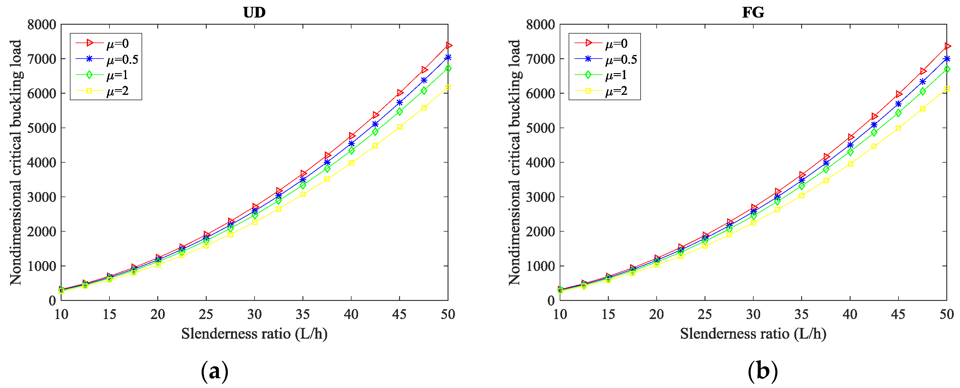
In addition, Table 6, Table 7 and Table 8 summarize the results of the nondimensional critical buckling load for different L/h ratios and nonlocal parameters µ, while considering a S-S, C-S, and C-C composite curved beams reinforced with CNTs, respectively. It is clear that the highest sensitivity of the buckling response of curved beams to the length-to-thickness ratio is obtained for C-C boundary conditions, followed by C-S, and S-S supports, respectively. Moreover, the highest value of the critical load is always reached in size-dependent composite curved beams with µ = 0, whereby as µ increases, the buckling load decreases, independently of the selected L/h ratios and CNTs distributions. A meaningful sensitivity of the response to the boundary conditions is also detected due to an expectable variation in the structural stiffness of the composite curved beams. Furthermore, Figure 4 illustrates the double effect of the nonlocal parameter and the slenderness ratio L/h on the nondimensional critical buckling load of CNTRC curved beams for fixed C-C boundary conditions and different CNTs distribution patterns (namely, a UD pattern in Figure 4a and an FG pattern in Figure 4b).
It is worth noting that the moderately thick CNTRC curved beam with L/h = 10 features the lowest critical buckling load. This last one increases as the length-to-thickness ratio L/h is increased, both in UD and FG-CNTRC curved beams. Another key aspect related to the sensitivity of the response with the nonlocal parameter is that the impact is more pronounced for higher values of L/h, (or equivalently to a lower thickness of the curved beam for a fixed length).
The effect of the opening angle and the nonlocal parameter on the nondimensional critical buckling load is shown in Table 9, Table 10 and Table 11 for S-S, C-S, and C-C CNTs reinforced composite curved beams, respectively. By exploiting comparatively, the results can be found that an increasing value of the opening angle decreases the buckling load whose value is also affected by the selected boundary condition. The results are obtained far from a size-dependence of the structure. It means that the buckling load of size-dependent and independent response of curved beams decreases by increasing the opening angle for each boundary conditions.
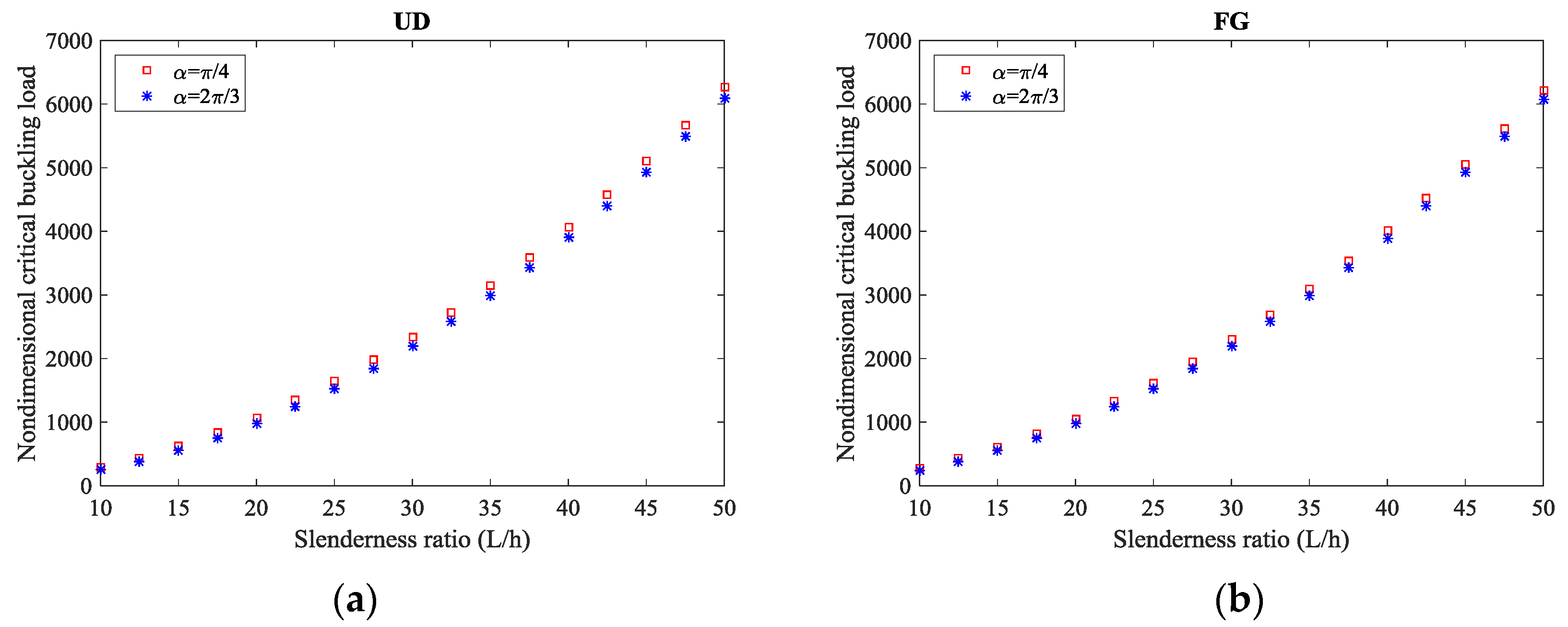
The double effect of the opening angle and slenderness ratio is finally emphasized in Figure 5 for each CNT reinforcement patterns, while considering a fixed C-C boundary condition. Based on this last plot, it is clearly visible that the higher sensitivity of the response for thick CNTs reinforced curved beams (i.e., for L/h = 50) compared to thin structures.

5. Conclusions

The size-dependent buckling of FG-CNTRC curved beams was investigated within the framework of a refined beam theory and Eringen nonlocal differential model. The CNTs distributions were considered uniform and graded through the thickness direction, and the material properties were estimated using the rule of mixtures. The Galerkin method was also employed to obtain the critical buckling load of FG-CNTRC curved beams for different boundary conditions. The effects of the nonlocal parameter, CNT volume fraction, slenderness ratio, opening angle, boundary conditions, and CNTs distribution scheme on the critical buckling load of FG-CNTRC curved beams were discussed in detail. Based on the numerical results, the following concluding remarks can be summarized:
An increase in CNT volume fraction leads to an increase in the critical buckling load for both UD- and FG-CNTRC curved beams.
A UD of CNTs in composite curved beams yields higher values of the critical buckling load compared to an FG distribution of CNTs.
An increase in the opening angle leads to a lower value of the critical buckling load for both UD- and FG-CNTRC curved beams.
The highest values of the critical buckling load of FG-CNTRC curved beams is obtained for completely clamped C-C boundary conditions, due to an increase in structural stiffness compared to simply supported boundary conditions.
Using nonlocality phenomena, the critical buckling load of FG-CNTRC curved beam decreases. Moreover, the effect of the nonlocal parameter in curved beams with higher slenderness ratios is more pronounced, if compared to lower slenderness ratios.

Author Contributions

Conceptualization, B.K., D.S., R.D. and F.T.; Formal analysis, D.S., M.J., R.D. and F.T.; Investigation, B.K. and F.T.; Validation, B.K., D.S., M.J., R.D., and F.T.; Writing-original draft, B.K., D.S. and M.J.; Writing-review & editing, R.D. and F.T.

Funding

This research received no external funding.

Conflicts of Interest

The authors declare no conflict of interest.

References

  1. Qian, D.; Dickey, E.C.; Andrews, R.; Rantell, T. Load transfer and deformation mechanisms in carbon nanotube-polystyrene composites. Appl. Phys. Lett. 2000, 76, 2868–2870. [Google Scholar] [CrossRef] [Green Version]
  2. Tornabene, F.; Fantuzzi, N.; Bacciocchi, M.; Viola, E. Effect of agglomeration on the natural frequencies of functionally graded carbon nanotube-reinforced laminated composite doubly-curved shells. Compos. Part B-Eng. 2016, 89, 187–218. [Google Scholar] [CrossRef]
  3. Fantuzzi, N.; Tornabene, F.; Bacciocchi, M.; Dimitri, R. Free vibration analysis of arbitrarily shaped Functionally Graded Carbon Nanotube-reinforced plates. Compos. Part B-Eng. 2017, 115, 384–408. [Google Scholar] [CrossRef]
  4. Tornabene, F.; Fantuzzi, N.; Bacciocchi, M. Linear static response of nanocomposite plates and shells reinforced by agglomerated carbon nanotubes. Compos. Part B-Eng. 2017, 115, 449–476. [Google Scholar] [CrossRef]
  5. Banić, D.; Bacciocchi, M.; Tornabene, F.; Ferreira, A.J.M. Influence of Winkler-Pasternak foundation on the vibrational behavior of plates and shells reinforced by agglomerated carbon nanotubes. Appl. Sci. 2017, 7, 1228. [Google Scholar] [CrossRef]
  6. Kiani, Y.; Dimitri, R.; Tornabene, F. Free vibration of FG-CNT reinforced composite skew cylindrical shells using the Chebyshev-Ritz formulation. Compos. Part B-Eng. 2018, 147, 169–177. [Google Scholar] [CrossRef]
  7. Bisheh, H.K.; Wu, N. Wave propagation in smart laminated composite cylindrical shells reinforced with carbon nanotubes in hygrothermal environments. Compos. Part B-Eng. 2019, 162, 219–241. [Google Scholar] [CrossRef]
  8. Khoshnevisa, H.; Tran, T.Q.; Mint, S.M.; Zadhoush, A.; Duong, H.M.; Youssefi, M. Effect of alignment and packing density on the stress relaxation process of carbon nanotube fibers spun from floating catalyst chemical vapor deposition method. Colloids Surf. A 2018, 558, 570–578. [Google Scholar] [CrossRef]
  9. Duong, H.M.; Tran, T.Q.; Kopp, R.; Mint, S.M.; Peng, L. Direct spinning of horizontally aligned carbon nanotube fibers and films from the floating catalyst method. Nanotube Superfiber Mater. 2019, 3–29. [Google Scholar] [CrossRef]
  10. Ansari, R.; Rouhi, H.; Sahmani, S. Calibration of the analytical nonlocal shell model for vibrations of double-walled carbon nanotubes with arbitrary boundary conditions using molecular dynamics. Int. J. Mech. Sci. 2011, 53, 786–792. [Google Scholar] [CrossRef]
  11. Lau, D.; Jian, W.; Yu, Z.; Hui, D. Nano-engineering of construction materials using molecular dynamics simulations: Prospects and challenges. Compos. Part B-Eng. 2018, 143, 282–291. [Google Scholar] [CrossRef]
  12. Rahman, R.; Foster, J. A molecular dynamics-based investigation of thermally vibrating graphene under different boundary conditions. Physica E 2015, 72, 25–47. [Google Scholar] [CrossRef]
  13. Xiang, Y.; Shen, H.S. Shear buckling of rippled graphene by molecular dynamics simulation. Mater. Today Comm. 2015, 3, 149–155. [Google Scholar] [CrossRef]
  14. Rouhi, S.; Shahnazari, A.; Ansari, R. Vibrational analysis of armchair phosphorene nanotubes by a DFT-based finite element model. Arch. Civ. Mech. Eng. 2018, 18, 611–621. [Google Scholar] [CrossRef]
  15. Soleimani, I.; Beni, Y.T. Vibration analysis of nanotubes based on two-node size dependent axisymmetric shell element. Arch. Civ. Mech. Eng. 2018, 18, 1345–1358. [Google Scholar] [CrossRef]
  16. Karami, B.; Janghorban, M.; Tounsi, A. Nonlocal strain gradient 3D elasticity theory for anisotropic spherical nanoparticles. Steel Comp. Struct. 2018, 27, 201–216. [Google Scholar]
  17. Shahsavari, D.; Karami, B.; Mansouri, S. Shear buckling of single layer graphene sheets in hygrothermal environment resting on elastic foundation based on different nonlocal strain gradient theories. Eur. J. Mech.-A/Solids 2018, 67, 200–214. [Google Scholar] [CrossRef]
  18. Ghasemi, A.R.; Mohandes, M.; Dimitri, R.; Tornabene, F. Agglomeration Effects on the Vibrations of CNTS/Fiber/Polymer/Metal Hybrid Laminates Cylindrical Shell. Compos. Part B-Eng. 2019, 167, 700–716. [Google Scholar] [CrossRef]
  19. Arefi, M.; Bidgoli, E.M.; Dimitri, R.; Tornabene, F. Free vibrations of functionally graded polymer composite nanoplates reinforced with graphene nanoplatelets. Aerosp. Sci. Technol. 2018, 81, 108–117. [Google Scholar] [CrossRef]
  20. Eringen, A.C. On differential equations of nonlocal elasticity and solutions of screw dislocation and surface waves. J. Appl. Phys. 1983, 54, 4703–4710. [Google Scholar] [CrossRef]
  21. Eringen, A.C.; Edelen, D. On nonlocal elasticity. Int. J. Eng. Sci. 1972, 10, 233–248. [Google Scholar] [CrossRef]
  22. Bouafia, K.; Kaci, A.; Houari, M.S.A.; Benzair, A.; Tounsi, A. A nonlocal quasi-3D theory for bending and free flexural vibration behaviors of functionally graded nanobeams. Smart Struct. Syst. 2017, 19, 115–126. [Google Scholar] [CrossRef]
  23. Shahsavari, D.; Karami, B.; Janghorban, M.; Li, L. Dynamic characteristics of viscoelastic nanoplates under moving load embedded within visco-Pasternak substrate and hygrothermal environment. Mater. Res Express 2017, 4, 085013. [Google Scholar] [CrossRef]
  24. Ganapathi, M.; Merzouki, T.; Polit, O. Vibration study of curved nanobeams based on nonlocal higher-order shear deformation theory using finite element approach. Compos. Struct. 2018, 184, 821–838. [Google Scholar] [CrossRef]
  25. Karami, B.; Janghorban, M.; Li, L. On guided wave propagation in fully clamped porous functionally graded nanoplates. Acta Astronaut. 2018, 143, 380–390. [Google Scholar] [CrossRef]
  26. Polit, O.; Merzouki, T.; Ganapathi, M. Elastic stability of curved nanobeam based on higher-order shear deformation theory and nonlocal analysis by finite element approach. Finite Elem. Anal Des. 2018, 146, 1–15. [Google Scholar] [CrossRef]
  27. Ganapathi, M.; Polit, O. A nonlocal higher-order model including thickness stretching effect for bending and buckling of curved nanobeams. Appl Math. Model. 2018, 57, 121–141. [Google Scholar] [CrossRef]
  28. Shahsavari, D.; Karami, B.; Fahham, H.R.; Li, L. On the shear buckling of porous nanoplates using a new size-dependent quasi-3D shear deformation theory. Acta Mech. 2018, 229, 4549–4573. [Google Scholar] [CrossRef]
  29. Shimpi, R.P.; Shetty, R.A.; Guha, A. A single variable shear deformable nonlocal theory for transversely loaded micro-and nano-scale rectangular beams. Sādhanā 2018, 43, 73. [Google Scholar] [CrossRef]
  30. Karami, B.; Shahsavari, D.; Janghorban, M. A comprehensive analytical study on functionally graded carbon nanotube-reinforced composite plates. Aerosp. Sci. Technol. 2018, 82, 499–512. [Google Scholar] [CrossRef]
  31. Hong, C.C. Rapid heating induced vibration of circular cylindrical shells with magnetostrictive functionally graded material. Arch. Civ. Mech. Eng. 2014, 14, 710–720. [Google Scholar] [CrossRef]
  32. Chen, D.; Yang, J.; Kitipornchai, S. Buckling and bending analyses of a novel functionally graded porous plate using Chebyshev-Ritz method. Arch. Civ. Mech. Eng. 2019, 19, 157–170. [Google Scholar] [CrossRef]
  33. Jouneghani, F.Z.; Dimitri, R.; Tornabene, F. Structural response of porous FG nanobeams under hygro-thermo-mechanical loadings. Compos. Part B-Eng. 2018, 152, 71–78. [Google Scholar] [CrossRef]
  34. Arefi, M.; Bidgoli, E.M.R.; Dimitri, R.; Bacciocchi, M.; Tornabene, F. Nonlocal bending analysis of curved nanobeams reinforced by graphene nanoplatelets. Compos. Part B-Eng. 2019, 166, 1–12. [Google Scholar] [CrossRef]
  35. Karami, B.; Shahsavari, D.; Janghorban, M.; Dimitri, R.; Tornabene, F. Wave propagation of porous nanoshells. Nanomaterials 2019, 9, 22. [Google Scholar] [CrossRef]
  36. Malikan, M.; Tornabene, F.; Dimitri, R. Nonlocal three-dimensional theory of elasticity for buckling behavior of functionally graded porous nanoplates using volume integrals. Mater. Res. Express 2018, 5, 095006. [Google Scholar] [CrossRef]
  37. Polit, O.; Anant, C.; Anirudh, B.; Ganapathi, M. Functionally graded graphene reinforced porous nanocomposite curved beams: Bending and elastic stability using a higher-order model with thickness stretch effect. Compos. Part B-Eng. 2018, 166, 310–327. [Google Scholar] [CrossRef]
  38. Malikan, M.; Dimitri, R.; Tornabene, F. Transient response of oscillated carbon nanotubes with an internal and external damping. Compos. Part B-Eng. 2019, 158, 198–205. [Google Scholar] [CrossRef]
  39. Mohammadi, M.; Arefi, M.; Dimitri, R.; Tornabene, F. Higher-order thermo-elastic analysis of FG-CNTRC cylindrical vessels surrounded by a Pasternak foundation. Nanomaterials 2019, 9, 79. [Google Scholar] [CrossRef]
  40. She, G.L.; Yuan, F.G.; Karami, B.; Ren, Y.R.; Xiao, W.S. On nonlinear bending behavior of FG porous curved nanotubes. Int. J. Eng. Sci. 2019, 135, 58–74. [Google Scholar] [CrossRef]
  41. Zhao, J.; Choe, K.; Shuai, C.; Wang, A.; Wang, Q. Free vibration analysis of functionally graded carbon nanotube reinforced composite truncated conical panels with general boundary conditions. Compos. Part B-Eng. 2019, 160, 225–240. [Google Scholar] [CrossRef]
  42. Shen, H.S. Nonlinear bending of functionally graded carbon nanotube-reinforced composite plates in thermal environments. Compos. Struct. 2009, 91, 9–19. [Google Scholar] [CrossRef]
  43. Han, Y.; Elliott, J. Molecular dynamics simulations of the elastic properties of polymer/carbon nanotube composites. Comp. Mater. Sci. 2007, 39, 315–323. [Google Scholar] [CrossRef]
  44. Ebrahimi, F.; Barati, M.R. A nonlocal strain gradient refined beam model for buckling analysis of size-dependent shear-deformable curved FG nanobeams. Compos. Struct. 2017, 159, 174–182. [Google Scholar] [CrossRef]
  45. Reddy, J.N. Nonlocal theories for bending, buckling and vibration of beams. Int. J. Eng. Sci. 2007, 45, 288–307. [Google Scholar] [CrossRef]
  46. Aydogdu, M. A general nonlocal beam theory: Its application to nanobeam bending, buckling and vibration. Physica E 2009, 41, 1651–1655. [Google Scholar] [CrossRef]
  47. Eltaher, M.; Emam, S.A.; Mahmoud, F. Static and stability analysis of nonlocal functionally graded nanobeams. Compos. Struct. 2013, 96, 82–88. [Google Scholar] [CrossRef]
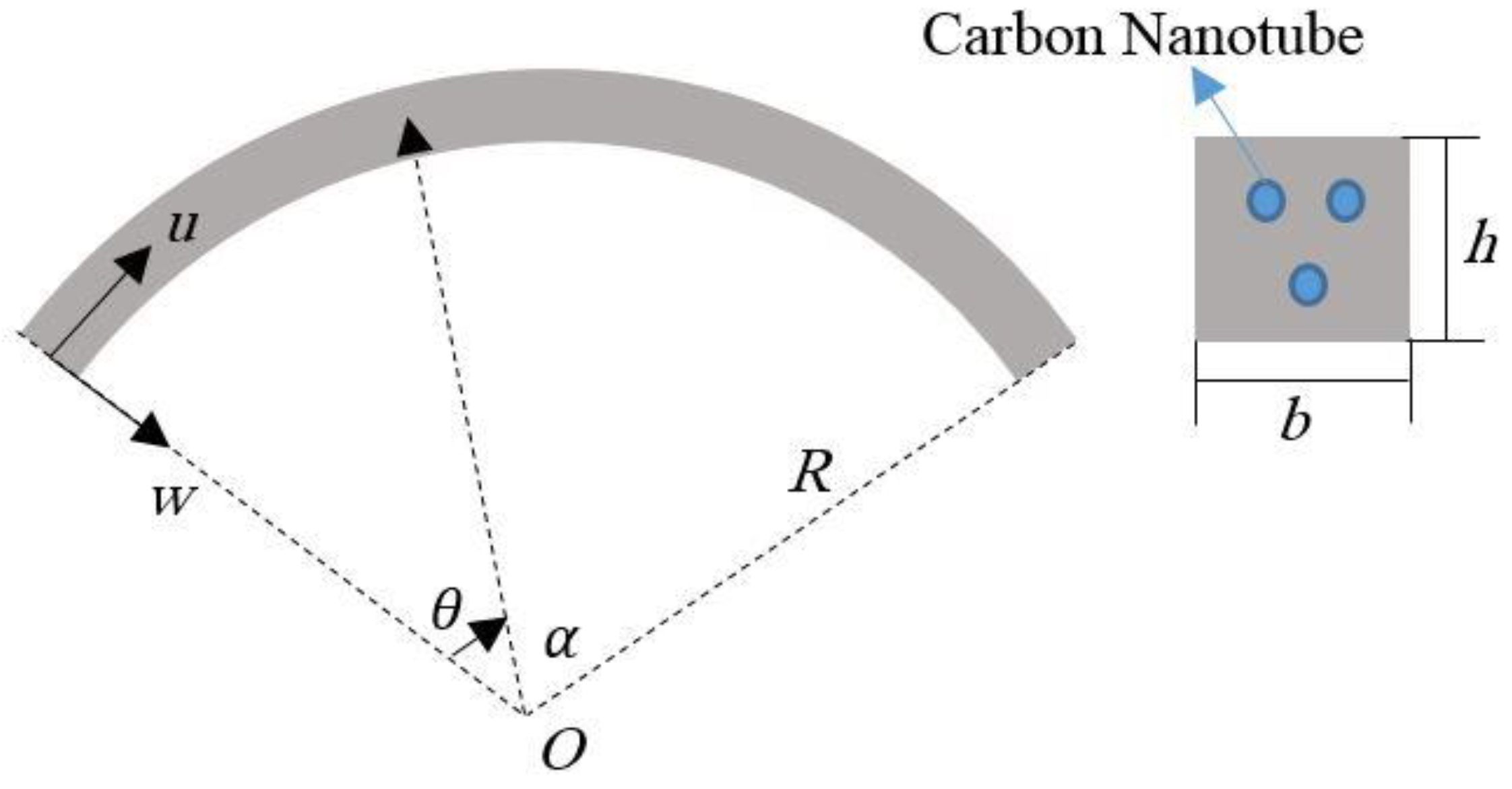
Figure 1. Geometry of a carbon nanotubes (CNTs) reinforced composite curved beam.
Molecules 24 02750 g001
Figure 2. Distribution schemes of CNTs along the thickness direction. UD = uniform distribution; FG = functionally graded.
Molecules 24 02750 g002
Figure 3. Critical buckling load versus slenderness ratio for different volume fractions and distribution patterns of CNTs: (a) UD pattern, (b) FG pattern. (µ = 2 nm2, L = 20, α = π/3).
Molecules 24 02750 g003
Figure 4. Critical buckling load versus slenderness ratio for different nonlocal parameters and distribution patterns of CNTs: (a) UD pattern, (b) FG pattern. (L = 20, α = π/3, V C N T * = 0.14).
Molecules 24 02750 g004
Figure 5. Critical buckling load versus slenderness ratio for different opening angles and distribution patterns of CNTs: (a) UD pattern, (b) FG pattern. (µ = 1 nm2, L = 20, V C N T * = 0.14).
Molecules 24 02750 g005
Table 1. Mechanical properties for a Poly{(m-phenylenevinylene)-co-[(2,5-dioctoxy-p-phenylene) vinylene]} (PmPV)/CNT composites reinforced by (10,10) SWCNT at the temperature T = 300 K.
V C N T * MD [43]Rule of Mixture
E11 (GPa)E22 (GPa)E11 (GPa)η1E22 (GPa)η2
0.1194.82.294.420.1492.200.934
0.14120.22.3120.380.1502.300.941
0.17145.63.5144.770.1403.491.381
Table 2. Nondimensional buckling force for a simply supported beam.
µReddy [45]Aydogdu [46]Eltaher [47]Present
09.86969.86969.869739.80601
18.98309.63198.983128.92692
28.24269.40558.242678.19176
37.61499.18947.614997.56846
47.07618.98307.076147.03246
Table 3. Nondimensional critical buckling load for simply- simply (S-S) CNTRC curved beams with L/h = 10, α = π/3.
V C N T * µ = 0µ = 0.5µ = 1µ = 1.5µ = 2µ = 3
UD-CNTRC0.1112.564212.411112.261712.115811.973411.6983
0.1414.353314.178414.007713.841113.678313.3641
0.1719.601519.362619.129518.901918.679718.2505
FG-CNTRC0.1110.10679.98359.86339.74599.63149.4101
0.1411.767811.624411.484411.347811.214410.9567
0.1715.668915.478015.291615.109714.932114.5890
Table 4. Nondimensional critical buckling load for clamped simply (C-S) CNTRC curved beams with L/h = 10, α = π/3.
V C N T * µ = 0µ = 0.5µ = 1µ = 1.5µ = 2µ = 3
UD-CNTRC0.11123.0005119.3204115.8541112.5835109.4924103.7931
0.14153.2617148.6762144.3571140.2818136.4303129.3288
0.17189.3549183.6894178.3532173.3182168.5597159.7857
FG-CNTRC0.11120.5401116.9336113.5366110.3314107.3022101.7169
0.14150.8821146.3677142.1157138.1037134.3120127.3207
0.17185.4017179.8545174.6296169.6998165.0406156.4498
Table 5. Nondimensional critical buckling load for clamped- clamped (C-C) CNTRC curved beams with L/h = 10, α = π/3.
V C N T * µ = 0µ = 0.5µ = 1µ = 1.5µ = 2µ = 3
UD-CNTRC0.11251.6676239.8324229.0603219.2143210.1798194.1748
0.14316.4206301.5402287.9965275.6171264.2581244.1351
0.17386.8498368.6573352.0990336.9642323.0770298.4749
FG-CNTRC0.11249.5883237.8509227.1678217.4031208.4433192.5705
0.14314.4762299.6872286.2267273.9234262.6343242.6349
0.17383.5269365.4907349.0746334.0698320.3018295.9111
Table 6. Effect of the slenderness ratio L/h on the nondimensional critical buckling load for S-S CNTRC curved beams with α = π/3, V C N T * = 0.14.
L/hµ = 0µ = 0.5µ = 1µ = 1.5µ = 2µ = 3
UD-CNTRC1014.353314.178414.007713.841113.678313.3641
2025.253724.945924.645624.352424.066023.5132
3029.445029.086228.736028.394128.060327.4156
5032.188131.795831.413031.039330.674429.9697
FG-CNTRC1011.767811.624411.484411.347811.214410.9567
2018.425618.201017.981917.768017.559117.1557
3020.657420.405720.160019.920219.686019.2337
5022.062021.793121.530721.274621.024420.5414
Table 7. Effect of the slenderness ratio L/h on the nondimensional critical buckling load for C-S CNTRC curved beams with α = π/3, V C N T * = 0.14.
L/hµ = 0µ = 0.5µ = 1µ = 1.5µ = 2µ = 3
UD-CNTRC10153.2617148.6762144.3571140.2818136.4303129.3288
20575.5663558.3455542.1252526.8208512.3568485.6873
301247.14061209.82651174.68041141.51871110.17791052.3904
503353.40993253.07683158.57323069.40542985.13382829.7502
FG-CNTRC10150.8821146.3677142.1157138.1037134.3120127.3207
20564.4312547.5436531.6372516.6288502.4446476.2911
301228.58521191.82631157.20311124.53481093.66031036.7326
503327.68443228.12103134.34243045.85862962.23342808.0419
Table 8. Effect of the slenderness ratio L/h on the nondimensional critical buckling load for C-C CNTRC curved beams with α = π/3, V C N T * = 0.14.
L/hµ = 0µ = 0.5µ = 1µ = 1.5µ = 2µ = 3
UD-CNTRC10316.4206301.5402287.9965275.6171264.2581244.1351
201230.37051172.50951119.84611071.71021027.5419949.2954
302714.60982586.94902470.75602364.55192267.10182094.4639
507393.54747045.84876729.38386440.12516174.70875704.5098
FG-CNTRC10314.4762299.6872286.2267273.9234262.6343242.6349
201218.49601161.19341109.03831061.36691017.6249940.1336
302691.13532564.57842449.39012344.10452247.49712076.3521
507355.77387009.85156695.00356407.22256143.16225675.3655
Table 9. Effect of the opening angle α on the nondimensional critical buckling load for S-S CNTRC curved beams with L/h = 10, V C N T * = 0.14.
αµ = 0µ = 0.5µ = 1µ = 1.5µ = 2µ = 3
UD-CNTRCπ/428.389128.043127.705527.375927.054026.4325
π/314.353314.178414.007713.841113.678313.3641
π/24.53934.48404.43004.37734.32584.2264
2π/31.40011.38301.36641.35011.33421.3036
FG-CNTRCπ/423.378423.093522.815522.544022.279021.7672
π/311.767811.624411.484411.347811.214410.9567
π/23.68893.64403.60013.55733.51553.4347
2π/31.12791.11411.10071.08761.07481.0501
Table 10. Effect of the opening angle α on the nondimensional critical buckling load for C-S CNTRC curved beams with L/h = 10, V C N T * = 0.14.
αµ = 0µ = 0.5µ = 1µ = 1.5µ = 2µ = 3
UD-CNTRCπ/4172.4731167.3128162.4523157.8662153.5319145.5402
π/3153.2617148.6762144.3571140.2818136.4303129.3288
π/2139.5855135.4092131.4754127.7638124.2560117.7882
2π/3134.8634130.8284127.0277123.4417120.0526113.8035
FG-CNTRCπ/4168.1669163.1354158.3962153.9246149.6986141.9064
π/3150.8821146.3677142.1157138.1037134.3120127.3207
π/2138.6057134.4586130.5525126.8670123.3838116.9614
2π/3134.3841130.3633126.5762123.0029119.6258113.3990
Table 11. Effect of the opening angle α on the nondimensional critical buckling load for C-C CNTRC curved beams with L/h = 10, V C N T * = 0.14.
αµ = 0µ = 0.5µ = 1µ = 1.5µ = 2µ = 3
UD-CNTRCπ/4337.8116321.9253307.4660294.2497282.1228260.6394
π/3316.4206301.5402287.9965275.6171264.2581244.1351
π/2301.1614286.9986274.1080262.3256251.5144232.3618
2π/3295.8488281.9358269.2726257.6981247.0776228.2628
FG-CNTRCπ/4334.3510318.6274304.3162291.2353279.2327257.9693
π/3314.4762299.6872286.2267273.9234262.6343242.6349
π/2300.3202286.1970273.3424261.5930250.8119231.7128
2π/3295.4045281.5124268.8683257.3111246.7066227.9201