
Redox Species of Redox Flow Batteries: A Review


Abstract
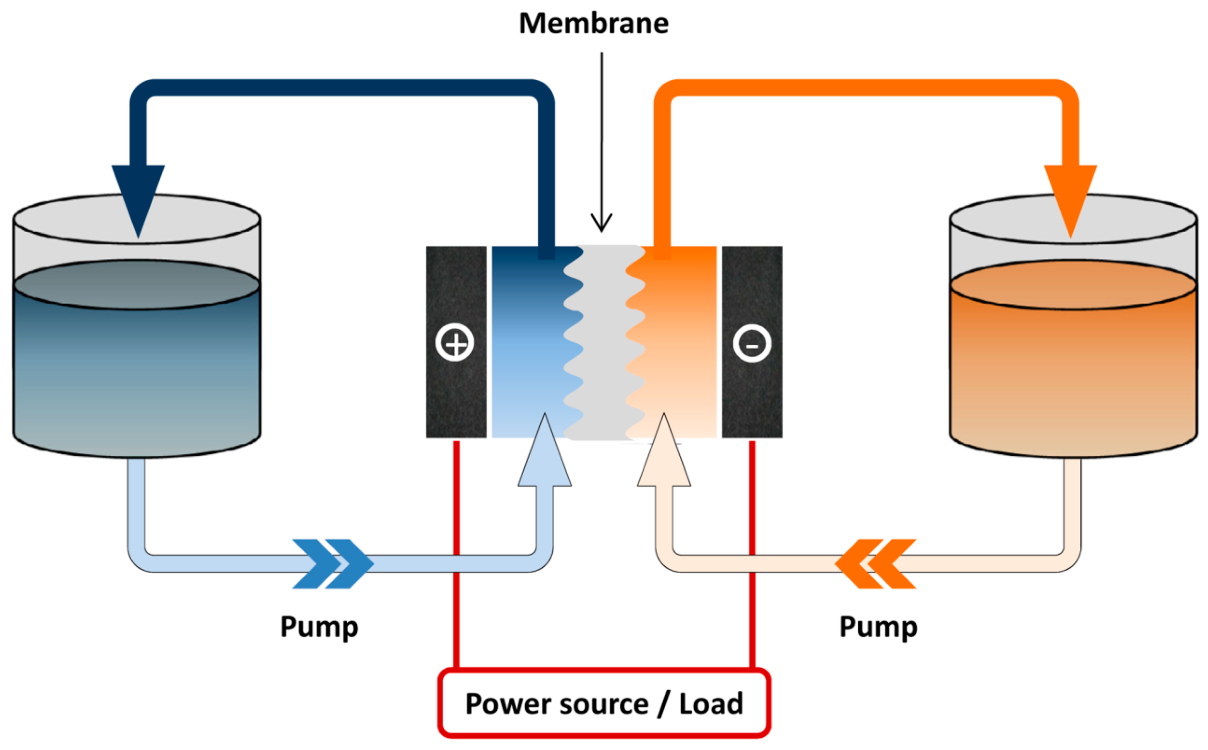
:1. Introduction

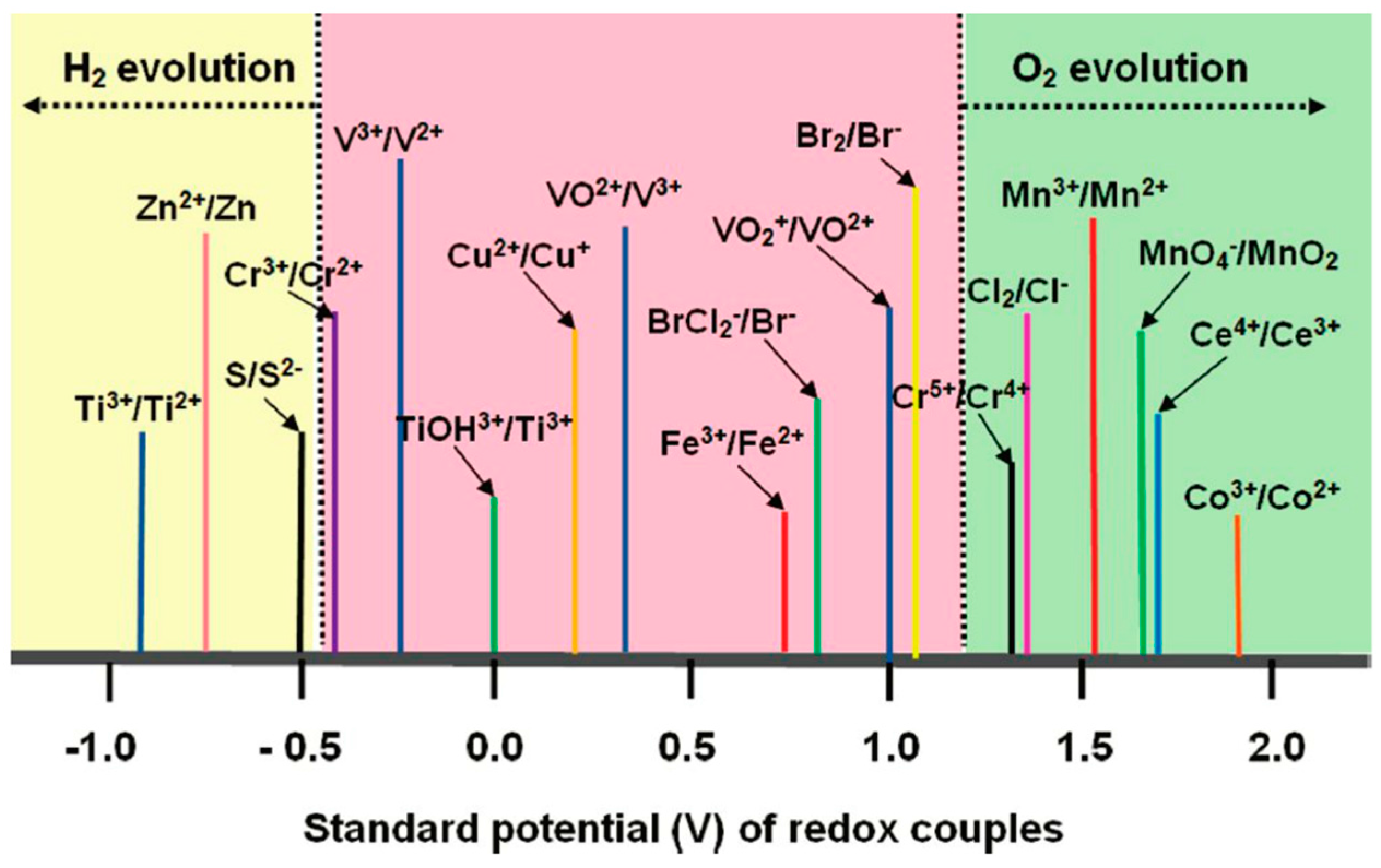
2. Simple Inorganic Ions
2.1. Iron/Chromium
2.2. All-Vanadium
2.3. Vanadium/Bromine

2.4. Zinc/Bromine

| Redox Species | Demonstrated Concentration/mol·L−1 | Redox Potential/V | Reference |
|---|---|---|---|
| VCl3/VCl2 | 1.0 | −0.58 vs. SCE | [16] |
| Br−/ClBr2− | 1.0 | 0.80 vs. SCE | [16] |
| Cl2/Cl− | 1.0 | −1.36 vs. SCE | [44] |
| Fe2+/Fe3+ | 2.0 | 0.77 vs. SHE | [23,24] |
| Cr3+/Cr2+ | 1.0 | −0.41 vs. SHE | [23,24] |
| Ti3+/Ti4+ | 1.1 | 0.04 vs. SHE | [19] |
| V3+/V2+ | 2.0 | −0.26 vs. SHE (2.00 M H2SO4) | [27] |
| VO2+/VO2+ | 2.0 | 1.00 vs. SHE (2.00 M H2SO4) | [27] |
| Zn/Zn2+ | −0.76 vs. SHE | [27] | |
| Br2/Br− | 2.0 | 1.09 vs. SHE | [27] |
| Ce3+/Ce2+ | 0.5 | 1.67 vs. SHE | [17] |
| Mn2+/Mn3+ | 0.3 | 1.51 vs. SHE | [18] |
| I3−/I− | 5.0 | 0.54 vs. SHE | [42] |
| VBr3/VBr2 | 3.0 | −0.26 vs. SHE | [29] |
3. Metal Complexes
4. Metal-Free Organic Compounds
| Redox Species | Demonstrated Concentration/M | Potential/V | Electrolyte | Reference |
|---|---|---|---|---|
| [Fe(bpy)3]2+/[Fe(bpy)3]3+ | 0.40 | 1.45 vs. Ag/Ag+ | 0.5 mol·L−1 TEABF4/PC | [46] |
| [Fe(bpy)3]+/[Fe(bpy)3]2+ | 0.20 | −1.12 vs. Ag/Ag+ | ||
| V(acac)3/[V(acac)3]+ | 0.05 | 0.45 vs. Ag/Ag+ | TBAPF4 in various solvents | [52,56,57,58,59] |
| V(acac)3/[V(acac)3]− | 0.05 | −1.75 vs. Ag/Ag+ | ||
| Cr(acac)3/[Cr(acac)3]+ | 0.05 | 1.20 vs. Ag/Ag+ | 0.5 mol·L−1 TEABF4/CH3CN | [54] |
| Cr(acac)3/[Cr(acac)3]− | 0.05 | −2.20 vs. Ag/Ag+ | ||
| Mn(acac)3/[Mn(acac)3]+ | 0.05 | 0.70 vs. Ag/Ag+ | 0.5 mol·L−1 TEABF4/CH3CN | [55] |
| Mn(acac)3/[Mn(acac)3]− | 0.05 | −0.40 vs. Ag/Ag+ | ||
| Ru(acac)3/[Ru(acac)3]+ | 0.002 | 1.17 vs. Ag/Ag+ | 1 mol·L−1 TEABF4/CH3CN | [53] |
| Ru(acac)3/[Ru(acac)3]+ | 0.002 | −0.60 vs. Ag/Ag+ | ||
| [Fe(bpy)3]2+/[Fe(bpy)3]3+ | 0.40 | 0.50 vs. Ag/Ag+ | 0.5 mol·L−1 Tetrabutylammonium hexafluorophosphate (TEAPF6)/CH3CN | [53] |
| [Fe(bpy)3]+/[Fe(bpy)3]2+ | 0.40 | −1.95 vs. Ag/Ag+ | ||
| [Ni(bpy)3]2+/[Ni(bpy)3]3+ | 0.20 | −1.70 vs. Ag/Ag+ | 0.5 mol·L−1 TEABF4/PC | [97] |
| Fc/Fc+ | 0.10 | 3.20–3.60 vs. Li/Li+ | Various electrolytes | [61,65] |
| CoCp2/CoCp2+ | 0.01 | −1.29 vs. Ag/Ag+ | 1 mol·L−1 TEAPF6/CH3CN | [61] |
| FcBr/FcBr+ | 0.01 | 0.26 vs. Ag/Ag+ | ||
| Bis(pentamethylcyclopentadienyl)cobalt (CoCp*2/CoCp*2+) | 0.01 | −1.83 vs. Ag/Ag+ | ||
| Auinoxaline-derivative 2,3,6-trimethylquinoxaline (TMeQ/TMeQ+) | 0.05 | 2.30 vs. Li/Li+ | 0.2 mol·L−1 LiBF4/PC | [77] |
| 3,7-bis(trifluoromethyl)-N-ethylphenothiazine (BCF3EPT/BCF3EPT) | 0.35 | 3.90 and 4.40 vs. Li/Li+ | 0.2 mol·L−1 LiBF4/PC | [80] |
| Fc1N112-TFSI | 0.80 | 3.49 vs. Li/Li+ | 1 mol·L−1 LiTFSI in EC/PC/EMC | [66] |
| 2,2,6,6-Tetramethylpiperidine-1-oxyl (TEMPO) | 2.00 | 3.50 vs. Li/Li+ | 2.3 mol·L−1 LiPF6 in EC/PC/EMC | [88] |
| 4-Methoxy-2,2,6,6-tetra-methylpiperidine1-oxyl (Meo-TEMPO) | MeO-TEMPO/LITFSI (1/1) + H2O(17% wt) | 3.50 vs. Li/Li+ | Ionic liquid | [89] |
| 9-fluorenone | 0.50 | −1.64 vs. Ag/Ag+ | Various lithium salts in DME or CH3CN [81] | [81] |
| 2,5-di-tert-Butyl-1-methoxy-4-[2′-methoxyethoxy]benzene (DBMMB) | 0.50 | 0.73 vs. Ag/Ag+ | ||
| 2,5-di-tert-Butyl-1,4-bis(2-methoxyethoxy)benzene (DBBB/DBBB+) | 0.05 | 4.00 vs. Li/Li+ | 0.2 mol·L−1 LiBF4/PC | [77] |
| V(mnt)32−/V(mnt)3− | 0.02 | −1.41 to −1.25 vs. SHE; | Various PF6− salts in CH3CN | [45] |
| V(mnt)3−/V(mnt)3 | 0.02 | −0.23 vs. SHE | ||
| 2,6-dihydroxyanthraquinone (2,6-DHAQ) | 0.50 | −0.70 vs. SHE | 1.0 M KOH/H2O | [75] |
| K4Fe(CN)6 | 0.4 | 0.50 vs. SHE |
5. Polysulfide/Sulfur
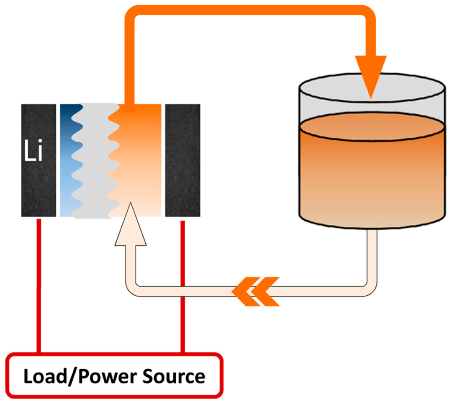
6. Li Metal
7. Semi-Solid Flow Battery
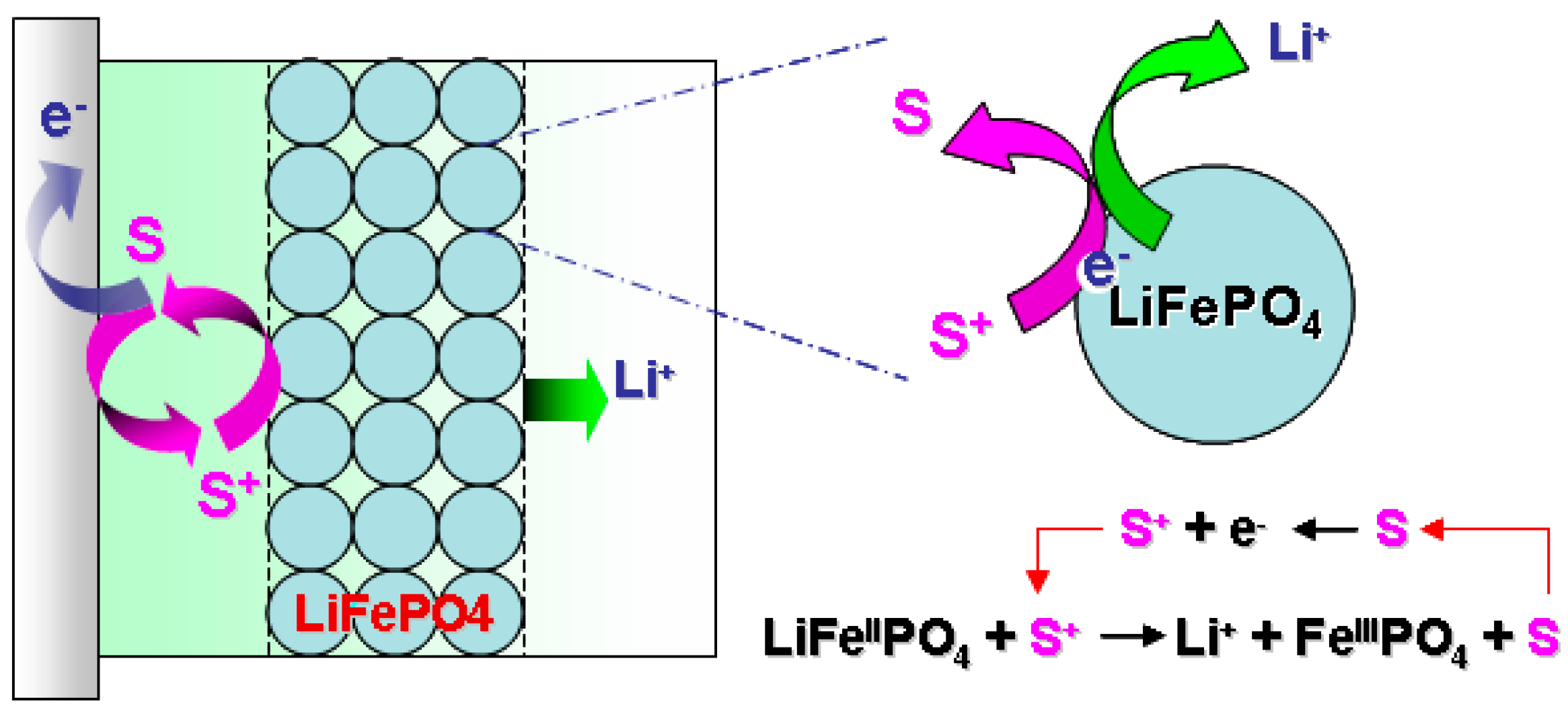
8. Redox Flow Lithium Ion Battery

9. Conclusions and Perspective
Acknowledgments
Author Contribution
Conflicts of Interest
References
- Lewis, N.S. Powering the planet. MRS Bull. 2007, 32, 808–820. [Google Scholar] [CrossRef]
- Echeverría, D.; Gass, P. The United States and China’s New Climate Change Commitments: Elements, Implications and Reactions; The International Institute for Sustainable Development: Winnipeg, MB, Canada, 2014. [Google Scholar]
- Larcher, D.; Tarascon, J.M. Towards greener and more sustainable batteries for electrical energy storage. Nat. Chem. 2015, 7, 19–29. [Google Scholar] [CrossRef] [PubMed]
- Skyllas-Kazacos, M.; Chakrabarti, M.H.; Hajimolana, S.A.; Mjalli, F.S.; Saleem, M. Progress in Flow Battery Research and Development. J. Electrochem. Soc. 2011, 158, R55–R79. [Google Scholar] [CrossRef]
- Thaller, L.H. Electrically rechargeable redox flow cell. In Proceedings of the 9th Intersociety Energy Conversion Engineering Conference, San Francisco, CA, USA, 26–30 August 1976.
- Weber, A.Z.; Mench, M.M.; Meyers, J.P.; Ross, P.N.; Gostick, J.T.; Liu, Q. Redox flow batteries: A review. J. Appl. Electrochem. 2011, 41, 1137–1164. [Google Scholar] [CrossRef]
- Alotto, P.; Guarnieri, M.; Moro, F. Redox flow batteries for the storage of renewable energy: A review. Renew. Sustain. Energy Rev. 2014, 29, 325–335. [Google Scholar] [CrossRef]
- Chiang, Y.-M. Building a better battery. Science 2010, 330, 1485–1486. [Google Scholar] [CrossRef] [PubMed]
- Wang, W.; Luo, Q.; Li, B.; Wei, X.; Li, L.; Yang, Z. Recent Progress in Redox Flow Battery Research and Development. Adv. Funct. Mater. 2013, 23, 970–986. [Google Scholar] [CrossRef]
- Chen, Y.W.D.; Santhanam, K.; Bard, A.J. Solution Redox Couples for Electrochemical Energy Storage I. Iron(III)-Iron(II) Complexes with O-Phenanthroline and Related Ligands. J. Electrochem. Soc. 1981, 128, 1460–1467. [Google Scholar] [CrossRef]
- Ponce de León, C.; Frías-Ferrer, A.; González-García, J.; Szánto, D.A.; Walsh, F.C. Redox flow cells for energy conversion. J. Power Sources 2006, 160, 716–732. [Google Scholar] [CrossRef]
- Li, X.; Zhang, H.; Mai, Z.; Zhang, H.; Vankelecom, I. Ion exchange membranes for vanadium redox flow battery (VRB) applications. Energy Environ. Sci. 2011, 4, 1147–1160. [Google Scholar] [CrossRef]
- Shin, S.-H.; Yun, S.-H.; Moon, S.-H. A review of current developments in non-aqueous redox flow batteries: Characterization of their membranes for design perspective. RSC Adv. 2013, 3, 9095–9116. [Google Scholar] [CrossRef]
- Leung, P.; Li, X.; Ponce de León, C.; Berlouis, L.; Low, C.T.J.; Walsh, F.C. Progress in redox flow batteries, remaining challenges and their applications in energy storage. RSC Adv. 2012, 2, 10125–10156. [Google Scholar] [CrossRef]
- Wang, Y.; He, P.; Zhou, H. Li-Redox Flow Batteries Based on Hybrid Electrolytes: At the Cross Road between Li-ion and Redox Flow Batteries. Adv. Energy Mater. 2012, 2, 770–779. [Google Scholar] [CrossRef]
- Skyllas-Kazacos, M. Novel vanadium chloride/polyhalide redox flow battery. J. Power Sources 2003, 124, 299–302. [Google Scholar] [CrossRef]
- Xia, X.; Liu, H.-T.; Liu, Y. Studies of the Feasibility of a Ce4+/Ce3+ V2+/V3+ Redox Cell. J. Electrochem. Soc. 2002, 149, A426–A430. [Google Scholar] [CrossRef]
- Xue, F.-Q.; Wang, Y.-L.; Wang, W.-H.; Wang, X.-D. Investigation on the electrode process of the Mn(II)/Mn(III) couple in redox flow battery. Electrochim. Acta 2008, 53, 6636–6642. [Google Scholar] [CrossRef]
- Wang, Y.; Lin, M.; Wan, C. A study of the discharge performance of the Ti/Fe redox flow system. J. Power Sources 1984, 13, 65–74. [Google Scholar] [CrossRef]
- Sanz, L.; Lloyd, D.; Magdalena, E.; Palma, J.; Kontturi, K. Description and performance of a novel aqueous all-copper redox flow battery. J. Power Sources 2014, 268, 121–128. [Google Scholar] [CrossRef]
- Peljo, P.; Lloyd, D.; Doan, N.; Majaneva, M.; Kontturi, K. Towards A Thermally Regenerative All-Copper Redox Flow Battery. Phys. Chem. Chem. Phys. 2014, 16, 2831–2835. [Google Scholar] [CrossRef] [PubMed]
- Wen, Y.; Zhang, H.; Qian, P.; Zhou, H.; Zhao, P.; Yi, B.; Yang, Y. Studies on Iron (Fe3+/Fe2+)-Complex/Bromine (Br2/Br−) Redox Flow Cell in Sodium Acetate Solution. J. Electrochem. Soc. 2006, 153, A929–A934. [Google Scholar] [CrossRef]
- Thaller, L. Redox flow cell energy storage systems. In Proceedings of the Terrestrial Energy Systems Conference, Orlando, FL, USA, 4–6 June 1979; American Institute of Aeronautics and Astronautics: New York, NY, USA, 1979. [Google Scholar]
- Gahn, R.F.; Hagedorn, N.H.; Ling, J.S. Single Cell Performance Studies on the Fe/Cr Redox Energy Storage System Using Mixed Reactant Solutions at Elevated Temperature; National Aeronautics and Space Administration, Lewis Research Center: Brook Park, OH, USA, 1983. [Google Scholar]
- Bae, C.H.; Roberts, E.P.L.; Dryfe, R.A.W. Chromium redox couples for application to redox flow batteries. Electrochim. Acta 2002, 48, 279–287. [Google Scholar] [CrossRef]
- Skyllas-Kazacos, M.; Grossmith, F. Efficient vanadium redox flow cell. J. Electrochem. Soc. 1987, 134, 2950–2953. [Google Scholar] [CrossRef]
- Sum, E.; Rychcik, M.; Skyllas-Kazacos, M. Investigation of the V(V)/V(IV) system for use in the positive half-cell of a redox battery. J. Power Sources 1985, 16, 85–95. [Google Scholar] [CrossRef]
- Rydh, C.J.; Sandén, B.A. Energy analysis of batteries in photovoltaic systems. Part II: Energy return factors and overall battery efficiencies. Energy Convers. Manag. 2005, 46, 1980–2000. [Google Scholar] [CrossRef]
- Skyllas-Kazacos, M.; Kazacos, G.; Poon, G.; Verseema, H. Recent advances with UNSW vanadium-based redox flow batteries. Int. J. Energy Res. 2010, 34, 182–189. [Google Scholar] [CrossRef]
- Díaz-González, F.; Sumper, A.; Gomis-Bellmunt, O.; Villafáfila-Robles, R. A review of energy storage technologies for wind power applications. Renew. Sustain. Energy Rev. 2012, 16, 2154–2171. [Google Scholar] [CrossRef]
- Dunn, B.; Kamath, H.; Tarascon, J.-M. Electrical energy storage for the grid: A battery of choices. Science 2011, 334, 928–935. [Google Scholar] [CrossRef] [PubMed]
- Soloveichik, G.L. Battery technologies for large-scale stationary energy storage. Annu. Rev. Chem. Biomol. Eng. 2011, 2, 503–527. [Google Scholar] [CrossRef] [PubMed]
- Tantisakon, T.; Holasut, K. Prospects of Carbon Based Micro-Fluid Electrolyte for the Vanadium Redox Flow Battery (VRB). Adv. Mater. Res. 2014, 931, 1083–1088. [Google Scholar] [CrossRef]
- Wang, W.; Kim, S.; Chen, B.; Nie, Z.; Zhang, J.; Xia, G.-G.; Li, L.; Yang, Z. A new redox flow battery using Fe/V redox couples in chloride supporting electrolyte. Energy Environ. Sci. 2011, 4, 4068–4073. [Google Scholar] [CrossRef]
- Hosseiny, S.S.; Saakes, M.; Wessling, M. A polyelectrolyte membrane-based vanadium/air redox flow battery. Electrochem. Commun. 2011, 13, 751–754. [Google Scholar] [CrossRef]
- Menictas, C.; Skyllas-Kazacos, M. Performance of vanadium-oxygen redox fuel cell. J. Appl. Electrochem. 2011, 41, 1223–1232. [Google Scholar] [CrossRef]
- Lim, H.; Lackner, A.; Knechtli, R. Zinc-bromine secondary battery. J. Electrochem. Soc. 1977, 124, 1154–1157. [Google Scholar] [CrossRef]
- Zhang, L.; Lai, Q.; Zhang, J.; Zhang, H. A high-energy-density redox flow battery based on zinc/polyhalide chemistry. ChemSusChem 2012, 5, 867–869. [Google Scholar] [CrossRef] [PubMed]
- Leung, P.K.; Ponce-de-León, C.; Low, C.T.J.; Shah, A.A.; Walsh, F.C. Characterization of a zinc–cerium flow battery. J. Power Sources 2011, 196, 5174–5185. [Google Scholar] [CrossRef]
- Manjunatha, H.; Suresh, G.S.; Venkatesha, T.V. Electrode materials for aqueous rechargeable lithium batteries. J. Solid State Electrochem. 2011, 15, 431–445. [Google Scholar] [CrossRef]
- Yang, Z.; Zhang, J.; Kintner-Meyer, M.C.; Lu, X.; Choi, D.; Lemmon, J.P.; Liu, J. Electrochemical energy storage for green grid. Chem. Rev. 2011, 111, 3577–3613. [Google Scholar] [CrossRef] [PubMed]
- Li, B.; Nie, Z.; Vijayakumar, M.; Li, G.; Liu, J.; Sprenkle, V.; Wang, W. Ambipolar zinc-polyiodide electrolyte for a high-energy density aqueous redox flow battery. Nature Commun. 2015, 6, 6303. [Google Scholar] [CrossRef] [PubMed]
- Kear, G.; Shah, A.A.; Walsh, F.C. Development of the all-vanadium redox flow battery for energy storage: A review of technological, financial and policy aspects. Int. J. Energy Res. 2012, 36, 1105–1120. [Google Scholar] [CrossRef]
- Linden, D.; Reddy, T.B. Handbook of Batteries; McGraw-Hill Companies, Inc.: New York, NY, USA, 2002. [Google Scholar]
- Cappillino, P.J.; Pratt, H.D.; Hudak, N.S.; Tomson, N.C.; Anderson, T.M.; Anstey, M.R. Application of Redox Non-Innocent Ligands to Non-Aqueous Flow Battery Electrolytes. Adv. Energy Mater. 2014, 4. [Google Scholar] [CrossRef]
- Matsuda, Y.; Tanaka, K.; Okada, M.; Takasu, Y.; Morita, M.; Matsumura-Inoue, T. A rechargeable redox battery utilizing ruthenium complexes with non-aqueous organic electrolyte. J. Appl. Electrochem. 1988, 18, 909–914. [Google Scholar] [CrossRef]
- Ibanez, J.G.; Choi, C.S.; Becker, R.S. Aqueous redox transition metal complexes for electrochemical applications as a function of pH. J. Electrochem. Soc. 1987, 134, 3083–3089. [Google Scholar] [CrossRef]
- Murthy, A.S.N.; Srivastava, T. Fe(III)/Fe(II)—Ligand systems for use as negative half-cells in redox-flow cells. J. Power Sources 1989, 27, 119–126. [Google Scholar] [CrossRef]
- Wen, Y.H.; Zhang, H.M.; Qian, P.; Zhou, H.T.; Zhao, P.; Yi, B.L.; Yang, Y.S. A study of the Fe(III)/Fe(II)–triethanolamine complex redox couple for redox flow battery application. Electrochim. Acta 2006, 51, 3769–3775. [Google Scholar] [CrossRef]
- Modiba, P.; Matoetoe, M.; Crouch, A.M. Kinetics study of transition metal complexes (Ce–DTPA, Cr–DTPA and V–DTPA) for redox flow battery applications. Electrochim. Acta 2013, 94, 336–343. [Google Scholar] [CrossRef]
- Mun, J.; Lee, M.-J.; Park, J.-W.; Oh, D.-J.; Lee, D.-Y.; Doo, S.-G. Non-Aqueous Redox Flow Batteries with Nickel and Iron Tris(2,2′-bipyridine) Complex Electrolyte. Electrochem. Solid State Lett. 2012, 15, A80–A82. [Google Scholar] [CrossRef]
- Liu, Q.; Sleightholme, A.E.S.; Shinkle, A.A.; Li, Y.; Thompson, L.T. Non-aqueous vanadium acetylacetonate electrolyte for redox flow batteries. Electrochem. Commun. 2009, 11, 2312–2315. [Google Scholar] [CrossRef]
- Chakrabarti, M.H.; Dryfe, R.A.W.; Roberts, E.P.L. Evaluation of electrolytes for redox flow battery applications. Electrochim. Acta 2007, 52, 2189–2195. [Google Scholar] [CrossRef]
- Liu, Q.; Shinkle, A.A.; Li, Y.; Monroe, C.W.; Thompson, L.T.; Sleightholme, A.E.S. Non-aqueous chromium acetylacetonate electrolyte for redox flow batteries. Electrochem. Commun. 2010, 12, 1634–1637. [Google Scholar] [CrossRef]
- Sleightholme, A.E.S.; Shinkle, A.A.; Liu, Q.; Li, Y.; Monroe, C.W.; Thompson, L.T. Non-aqueous manganese acetylacetonate electrolyte for redox flow batteries. J. Power Sources 2011, 196, 5742–5745. [Google Scholar] [CrossRef]
- Herr, T.; Noack, J.; Fischer, P.; Tübke, J. 1,3-Dioxolane, tetrahydrofuran, acetylacetone and dimethyl sulfoxide as solvents for non-aqueous vanadium acetylacetonate redox-flow-batteries. Electrochim. Acta 2013, 113, 127–133. [Google Scholar] [CrossRef]
- Shinkle, A.A.; Sleightholme, A.E.S.; Thompson, L.T.; Monroe, C.W. Electrode kinetics in non-aqueous vanadium acetylacetonate redox flow batteries. J. Appl. Electrochem. 2011, 41, 1191–1199. [Google Scholar] [CrossRef]
- Shinkle, A.A.; Pomaville, T.J.; Sleightholme, A.E.S.; Thompson, L.T.; Monroe, C.W. Solvents and supporting electrolytes for vanadium acetylacetonate flow batteries. J. Power Sources 2014, 248, 1299–1305. [Google Scholar] [CrossRef]
- Shinkle, A.A.; Sleightholme, A.E.S.; Griffith, L.D.; Thompson, L.T.; Monroe, C.W. Degradation mechanisms in the non-aqueous vanadium acetylacetonate redox flow battery. J. Power Sources 2012, 206, 490–496. [Google Scholar] [CrossRef]
- Astruc, D. Electron-reservoir complexes and other redox-robust reagents: Functions and applications. New J. Chem. 2009, 33, 1191–1206. [Google Scholar] [CrossRef]
- Hwang, B.; Park, M.S.; Kim, K. Ferrocene and Cobaltocene Derivatives for Non-Aqueous Redox Flow Batteries. ChemSusChem 2015, 8, 310–314. [Google Scholar] [CrossRef] [PubMed]
- Allen, J.B.; Larry, R.F. Electrochemical Methods: Fundamentals and Applications; Department of Chemistry and Biochemistry University of Texas at Austin: Austin, TX, USA; John Wiley & Sons, Inc.: New York, NY, USA, 2001; pp. 156–176. [Google Scholar]
- Ates, M.N.; Allen, C.J.; Mukerjee, S.; Abraham, K.M. Electronic Effects of Substituents on Redox Shuttles for Overcharge Protection of Li-ion Batteries. J. Electrochem. Soc. 2012, 159, A1057–A1064. [Google Scholar] [CrossRef]
- Laoire, C.O.; Plichta, E.; Hendrickson, M.; Mukerjee, S.; Abraham, K.M. Electrochemical studies of ferrocene in a lithium ion conducting organic carbonate electrolyte. Electrochim. Acta 2009, 54, 6560–6564. [Google Scholar] [CrossRef]
- Zhao, Y.; Ding, Y.; Song, J.; Li, G.; Dong, G.; Goodenough, J.B.; Yu, G. Sustainable Electrical Energy Storage through the Ferrocene/Ferrocenium Redox Reaction in Aprotic Electrolyte. Angew. Chem. Int. Ed. 2014, 53, 11036–11040. [Google Scholar] [CrossRef] [PubMed]
- Wei, X.; Cosimbescu, L.; Xu, W.; Hu, J.Z.; Vijayakumar, M.; Feng, J.; Hu, M.Y.; Deng, X.; Xiao, J.; Liu, J.; et al. Towards High-Performance Nonaqueous Redox Flow Electrolyte via Ionic Modification of Active Species. Adv. Energy Mater. 2015, 5. [Google Scholar] [CrossRef]
- Armand, M.; Tarascon, J.-M. Building better batteries. Nature 2008, 451, 652–657. [Google Scholar] [CrossRef] [PubMed]
- Yao, M.; Senoh, H.; Yamazaki, S.-I.; Siroma, Z.; Sakai, T.; Yasuda, K. High-capacity organic positive-electrode material based on a benzoquinone derivative for use in rechargeable lithium batteries. J. Power Sources 2010, 195, 8336–8340. [Google Scholar] [CrossRef]
- Zhang, L.; Zhang, Z.; Redfern, P.C.; Curtiss, L.A.; Amine, K. Molecular engineering towards safer lithium-ion batteries: A highly stable and compatible redox shuttle for overcharge protection. Energy Environ. Sci. 2012, 5, 8204–8207. [Google Scholar] [CrossRef]
- Senoh, H.; Yao, M.; Sakaebe, H.; Yasuda, K.; Siroma, Z. A two-compartment cell for using soluble benzoquinone derivatives as active materials in lithium secondary batteries. Electrochim. Acta 2011, 56, 10145–10150. [Google Scholar] [CrossRef]
- Biilmann, E. Oxidation and reduction potentials of organic compounds. Trans. Faraday Soc. 1924, 19, 676–691. [Google Scholar] [CrossRef]
- Xu, Y.; Wen, Y.; Cheng, J.; Yanga, Y.; Xie, Z.; Cao, G. Novel organic redox flow batteries using soluble quinonoid compounds as positive materials. In Proceedings of the World Non-Grid-Connected Wind Power and Energy Conference, Nanjing, China, 24–26 September 2009; pp. 1–4.
- Huskinson, B.; Marshak, M.P.; Suh, C.; Er, S.; Gerhardt, M.R.; Galvin, C.J.; Chen, X.; Aspuru-Guzik, A.; Gordon, R.G.; Aziz, M.J. A metal-free organic–inorganic aqueous flow battery. Nature 2014, 505, 195–198. [Google Scholar] [CrossRef] [PubMed]
- Yang, B.; Hoober-Burkhardt, L.; Wang, F.; Surya Prakash, G.K.; Narayanan, S.R. An Inexpensive Aqueous Flow Battery for Large-Scale Electrical Energy Storage Based on Water-Soluble Organic Redox Couples. J. Electrochem. Soc. 2014, 161, A1371–A1380. [Google Scholar] [CrossRef]
- Lin, K.; Chen, Q.; Gerhardt, M.R.; Tong, L.; Kim, S.B.; Eisenach, L.; Valle, A.W.; Hardee, D.; Gordon, R.G.; Aziz, M.J. Alkaline quinone flow battery. Science 2015, 349, 1529–1532. [Google Scholar] [CrossRef] [PubMed]
- Wang, W.; Xu, W.; Cosimbescu, L.; Choi, D.; Li, L.; Yang, Z. Anthraquinone with tailored structure for a nonaqueous metal-organic redox flow battery. Chem. Commun. 2012, 48, 6669–6671. [Google Scholar] [CrossRef] [PubMed]
- Brushett, F.R.; Vaughey, J.T.; Jansen, A.N. An All-Organic Non-aqueous Lithium-Ion Redox Flow Battery. Adv. Energy Mater. 2012, 2, 1390–1396. [Google Scholar] [CrossRef]
- Matsunaga, T.; Kubota, T.; Sugimoto, T.; Satoh, M. High-performance Lithium Secondary Batteries Using Cathode Active Materials of Triquinoxalinylenes Exhibiting Six Electron Migration. Chem. Lett. 2011, 40, 750–752. [Google Scholar] [CrossRef]
- Huang, J.; Cheng, L.; Assary, R.S.; Wang, P.; Xue, Z.; Burrell, A.K.; Curtiss, L.A.; Zhang, L. Liquid Catholyte Molecules for Nonaqueous Redox Flow Batteries. Adv. Energy Mater. 2014, 5. [Google Scholar] [CrossRef]
- Kaur, A.P.; Holubowitch, N.E.; Ergun, S.; Elliott, C.F.; Odom, S.A. A Highly Soluble Organic Catholyte for Non-Aqueous Redox Flow Batteries. Energy Technol. 2015, 3, 476–480. [Google Scholar] [CrossRef]
- Wei, X.; Xu, W.; Huang, J.; Zhang, L.; Walter, E.; Lawrence, C.; Vijayakumar, M.; Henderson, W.A.; Liu, T.; Cosimbescu, L.; et al. Radical Compatibility with Nonaqueous Electrolytes and Its Impact on an All-Organic Redox Flow Battery. Angew. Chem. Int. Ed. Engl. 2015, 54, 8684–8687. [Google Scholar] [CrossRef] [PubMed]
- Nakahara, K.; Oyaizu, K.; Nishide, H. Organic Radical Battery Approaching Practical Use. Chem. Lett. 2011, 40, 222–227. [Google Scholar] [CrossRef]
- Nakahara, K.; Iwasa, S.; Satoh, M.; Morioka, Y.; Iriyama, J.; Suguro, M.; Hasegawa, E. Rechargeable batteries with organic radical cathodes. Chem. Phys. Lett. 2002, 359, 351–354. [Google Scholar] [CrossRef]
- Bergner, B.J.; Schurmann, A.; Peppler, K.; Garsuch, A.; Janek, J. TEMPO: A mobile catalyst for rechargeable Li-O(2) batteries. J. Am. Chem. Soc. 2014, 136, 15054–15064. [Google Scholar] [CrossRef] [PubMed]
- Shiga, T.; Hase, Y.; Yagi, Y.; Takahashi, N.; Takechi, K. Catalytic Cycle Employing a TEMPO–Anion Complex to Obtain a Secondary Mg–O2Battery. J. Phys. Chem. Lett. 2014, 5, 1648–1652. [Google Scholar] [CrossRef] [PubMed]
- Moshurchak, L.M.; Buhrmester, C.; Wang, R.L.; Dahn, J.R. Comparative studies of three redox shuttle molecule classes for overcharge protection of LiFePO4-based Li-ion cells. Electrochim. Acta 2007, 52, 3779–3784. [Google Scholar] [CrossRef]
- Taggougui, M.; Carré, B.; Willmann, P.; Lemordant, D. Application of a nitroxide radical as overcharge protection in rechargeable lithium batteries. J. Power Sources 2007, 174, 643–647. [Google Scholar] [CrossRef]
- Wei, X.; Xu, W.; Vijayakumar, M.; Cosimbescu, L.; Liu, T.; Sprenkle, V.; Wang, W. TEMPO-Based Catholyte for High-Energy Density Nonaqueous Redox Flow Batteries. Adv. Mater. 2014, 26, 7649–7653. [Google Scholar] [CrossRef] [PubMed]
- Takechi, K.; Kato, Y.; Hase, Y. A Highly Concentrated Catholyte Based on a Solvate Ionic Liquid for Rechargeable Flow Batteries. Adv. Mater. 2015, 27, 2501–2506. [Google Scholar] [CrossRef] [PubMed]
- Kolosnitsyn, V.S.; Karaseva, E.V. Lithium-sulfur batteries: Problems and solutions. Russ. J. Electrochem. 2008, 44, 506–509. [Google Scholar] [CrossRef]
- Price, A.; Bartley, S.; Male, S.; Cooley, G. A novel approach to utility-scale energy storage. Power Eng. J. 1999, 13, 122–129. [Google Scholar] [CrossRef]
- Remick, R.; Ang, P. Electrically Rechargeable Anionically Active Reduction-Oxidation Electrical Storage-Supply System. U.S. Patent 4485154, 27 November 1984. [Google Scholar]
- Szanto, D.A. Characterisation of Electrochemical Filter-Press Reactors. Ph.D. Thesis, University of Portsmouth, Portsmouth, UK, 1999. [Google Scholar]
- Pan, H.; Wei, X.; Henderson, W.A.; Shao, Y.; Chen, J.; Bhattacharya, P.; Xiao, J.; Liu, J. On the Way Toward Understanding Solution Chemistry of Lithium Polysulfides for High Energy Li-S Redox Flow Batteries. Adv. Energy Mater. 2015, 5. [Google Scholar] [CrossRef]
- Yang, Y.; Zheng, G.; Cui, Y. A membrane-free lithium/polysulfide semi-liquid battery for large-scale energy storage. Energy Environ. Sci. 2013, 6, 1552–1558. [Google Scholar] [CrossRef]
- Lowe, M.A.; Gao, J.; Abruna, H.D. Mechanistic insights into operational lithium-sulfur batteries by in situ X-ray diffraction and absorption spectroscopy. RSC Adv. 2014, 4, 18347–18353. [Google Scholar] [CrossRef]
- Kim, J.-H.; Kim, K.J.; Park, M.-S.; Lee, N.J.; Hwang, U.; Kim, H.; Kim, Y.-J. Development of metal-based electrodes for non-aqueous redox flow batteries. Electrochem. Commun. 2011, 13, 997–1000. [Google Scholar] [CrossRef]
- Ding, F.; Xu, W.; Graff, G.L.; Zhang, J.; Sushko, M.L.; Chen, X.; Shao, Y.; Engelhard, M.H.; Nie, Z.; Xiao, J.; et al. Dendrite-free lithium deposition via self-healing electrostatic shield mechanism. J. Am. Chem. Soc. 2013, 135, 4450–4456. [Google Scholar] [CrossRef] [PubMed]
- Lu, Y.; Goodenough, J.B. Rechargeable alkali-ion cathode-flow battery. J. Mater. Chem. 2011, 21, 10113–10117. [Google Scholar] [CrossRef]
- Lu, Y.; Goodenough, J.B.; Kim, Y. Aqueous cathode for next-generation alkali-ion batteries. J. Am. Chem. Soc. 2011, 133, 5756–5759. [Google Scholar] [CrossRef] [PubMed]
- Bauer, I.; Thieme, S.; Brückner, J.; Althues, H.; Kaskel, S. Reduced polysulfide shuttle in lithium–sulfur batteries using Nafion-based separators. J. Power Sources 2014, 251, 417–422. [Google Scholar] [CrossRef]
- Ding, Y.; Zhao, Y.; Yu, G. A Membrane-Free Ferrocene-Based High-Rate Semiliquid Battery. Nano Lett. 2015, 15, 4108–4113. [Google Scholar] [CrossRef] [PubMed]
- Zhao, Y.; Ding, Y.; Song, J.; Peng, L.; Goodenough, J.B.; Yu, G. A reversible Br2/Br− redox couple in the aqueous phase as a high-performance catholyte for alkali-ion batteries. Energy Environ. Sci. 2014, 7, 1990–1995. [Google Scholar] [CrossRef]
- Zhao, Y.; Byon, H.R. High-Performance Lithium-Iodine Flow Battery. Adv. Energy Mater. 2013, 3, 1630–1635. [Google Scholar] [CrossRef]
- Zhao, Y.; Hong, M.; Bonnet Mercier, N.; Yu, G.; Choi, H.C.; Byon, H.R. A 3.5 V lithium-iodine hybrid redox battery with vertically aligned carbon nanotube current collector. Nano Lett. 2014, 14, 1085–1092. [Google Scholar] [CrossRef] [PubMed]
- Zhao, Y.; Wang, L.; Byon, H.R. High-performance rechargeable lithium-iodine batteries using triiodide/iodide redox couples in an aqueous cathode. Nat. Commun. 2013, 4. [Google Scholar] [CrossRef] [PubMed]
- Duduta, M.; Ho, B.; Wood, V.C.; Limthongkul, P.; Brunini, V.E.; Carter, W.C.; Chiang, Y.-M. Semi-Solid Lithium Rechargeable Flow Battery. Adv. Energy Mater. 2011, 1, 511–516. [Google Scholar] [CrossRef]
- Hamelet, S.; Larcher, D.; Dupont, L.; Tarascon, J.M. Silicon-Based Non Aqueous Anolyte for Li Redox-Flow Batteries. J. Electrochem. Soc. 2013, 160, A516–A520. [Google Scholar] [CrossRef]
- Fan, F.Y.; Woodford, W.H.; Li, Z.; Baram, N.; Smith, K.C.; Helal, A.; McKinley, G.H.; Carter, W.C.; Chiang, Y.M. Polysulfide flow batteries enabled by percolating nanoscale conductor networks. Nano Lett. 2014, 14, 2210–2218. [Google Scholar] [CrossRef] [PubMed]
- Chen, H.; Zou, Q.; Liang, Z.; Liu, H.; Li, Q.; Lu, Y.C. Sulphur-impregnated flow cathode to enable high-energy-density lithium flow batteries. Nature Commun. 2015, 6. [Google Scholar] [CrossRef] [PubMed]
- Ventosa, E.; Buchholz, D.; Klink, S.; Flox, C.; Chagas, L.G.; Vaalma, C.; Schuhmann, W.; Passerini, S.; Morante, J.R. Non-aqueous semi-solid flow battery based on Na-ion chemistry. P2-type NaxNi0.22Co0.11Mn0.66O2-NaTi2(PO4)3. Chem. Commun. 2015, 51, 7298–7301. [Google Scholar] [CrossRef] [PubMed]
- Li, Z.; Smith, K.C.; Dong, Y.; Baram, N.; Fan, F.Y.; Xie, J.; Limthongkul, P.; Carter, W.C.; Chiang, Y.M. Aqueous semi-solid flow cell: Demonstration and analysis. Phys. Chem. Chem. Phys. 2013, 15, 15833–15839. [Google Scholar] [CrossRef] [PubMed]
- Janoschka, T.; Martin, N.; Martin, U.; Friebe, C.; Morgenstern, S.; Hiller, H.; Hager, M.D.; Schubert, U.S. An aqueous, polymer-based redox-flow battery using non-corrosive, safe, and low-cost materials. Nature 2015, 527, 78–81. [Google Scholar] [CrossRef] [PubMed]
- Wei, T.-S.; Fan, F.Y.; Helal, A.; Smith, K.C.; McKinley, G.H.; Chiang, Y.-M.; Lewis, J.A. Biphasic Electrode Suspensions for Li-Ion Semi-solid Flow Cells with High Energy Density, Fast Charge Transport, and Low-Dissipation Flow. Adv. Energy Mater. 2015, 5. [Google Scholar] [CrossRef]
- Wang, Q.; Zakeeruddin, S.M.; Wang, D.; Exnar, I.; Gratzel, M. Redox targeting of insulating electrode materials: A new approach to high-energy-density batteries. Angew. Chem. Int. Ed. Engl. 2006, 45, 8197–8200. [Google Scholar] [CrossRef] [PubMed]
- Huang, Q.; Li, H.; Gratzel, M.; Wang, Q. Reversible chemical delithiation/lithiation of LiFePO4: Towards a redox flow lithium-ion battery. Phys. Chem. Chem. Phys. 2013, 15, 1793–1797. [Google Scholar] [CrossRef] [PubMed]
- Pan, F.; Yang, J.; Huang, Q.; Wang, X.; Huang, H.; Wang, Q. Redox Targeting of Anatase TiO2 for Redox Flow Lithium-Ion Batteries. Adv. Energy Mater. 2014, 4. [Google Scholar] [CrossRef]
© 2015 by the authors. Licensee MDPI, Basel, Switzerland. This article is an open access article distributed under the terms and conditions of the Creative Commons by Attribution (CC-BY) license ( http://creativecommons.org/licenses/by/4.0/).
Share and Cite
Pan, F.; Wang, Q. Redox Species of Redox Flow Batteries: A Review. Molecules 2015, 20, 20499-20517. https://doi.org/10.3390/molecules201119711
Pan F, Wang Q. Redox Species of Redox Flow Batteries: A Review. Molecules. 2015; 20(11):20499-20517. https://doi.org/10.3390/molecules201119711
Chicago/Turabian StylePan, Feng, and Qing Wang. 2015. "Redox Species of Redox Flow Batteries: A Review" Molecules 20, no. 11: 20499-20517. https://doi.org/10.3390/molecules201119711