Article

Two Examples of Exergy Optimization Regarding the “Thermo-Frigopump” and Combined Heat and Power Systems

Laboratoire d'Energétique et de Mécanique Théorique et Appliquée (LEMTA), Université de Lorraine, 2 avenue de la Forêt de Haye, 54518 Vandoeuvre, France
Entropy 2013, 15(2), 544-558; https://doi.org/10.3390/e15020544
Submission received: 29 November 2012 / Revised: 17 January 2013 / Accepted: 18 January 2013 / Published: 1 February 2013

Abstract

:
In a recent review an optimal thermodynamics and associated new upper bounds have been proposed, but it was only relative to power delivered by engines. In fact, it appears that for systems and processes with more than one utility (mainly mechanical or electrical power), energy conservation (First Law) is limited for representing their efficiency. Consequently, exergy analysis combining the First and Second Law seems essential for optimization of systems or processes situated in their environment. For thermomechanical systems recent papers report on comparisons between energy and exergy analysis and corresponding optimization, but the proposed models mainly use heat transfer conductance modelling, except for internal combustion engine. Here we propose to reconsider direct and inverse configurations of Carnot machines, with two examples. The first example is concerned with “thermofrigo-pump” where the two utilities are hot and cold thermal exergies due to the difference in the temperature level compared to the ambient one. The second one is relative to a “combined heat and power” (CHP) system. In the two cases, the model is developed based on the Carnot approach, and use of the efficiency-NTU method to characterize the heat exchangers. Obtained results are original thermodynamics optima, that represent exergy upper bounds for these two cases. Extension of the proposed method to other systems and processes is examined, with added technical constraints or not.

1. Introduction

A cogeneration plant, also called a Combined Heat and Power (CHP) production system, or “thermo-frigopump”, can operate at efficiencies greater than those achieved when heat and power are produced in separate or distinct processes. For example, efficiency values go from 35%–40% for electrical or mechanical production, to 80%–85% for the cogeneration system efficiency [1]. The environmental issue should be also considered as an important system advantage with respect to carbon dioxide emissions, which are mainly responsible for the greenhouse effect.
In the recent past, due to environmental impact considerations and energy efficient use purposes, a renewal and development of heat pump and combined heat and power systems was increasing from large to small scale systems, even μCHP, and for industrial or building applications [1,2,3,4,5,6,7,8,9,10,11,12,13,14]. New configurations of systems were studied and among them photovoltaic/thermal (PV/T) configurations [15,16,17] or fuel cell CHP systems [2,4,14] are close to implementation in the near future. Analysis of the CO2 mitigation costs of large-scale biomass-fired cogeneration technologies with CO2 capture and storage was performed [18,19], showing that biomass-fired cogeneration plants based on integrated gasification combined cycle technology (CHP-BIGCC) is very energy and emission efficient and also cost competitive compared with other conversion systems. A new analytical approach based on the current models of the solid oxide fuel cell and gas turbine was elaborated [20], in which multiple irreversibilities existing in real hybrid systems are taken into account. The general performance characteristics of the hybrid system (irreversible solid oxide fuel cell-gas turbine) were revealed and the optimum criteria of the main performance parameters were determined. Other hybrid systems were considered [21], such as bi-energy technologies (gas and electricity), as a path to transfer loads from one system to another, so an absolute peak load reduction by 17% at the small scale was found. A novel conceptualisation considering the steam cycle of a combined heat and power generator thermodynamically equivalent to a conventional steam cycle generator plus an additional virtual steam cycle heat pump [22] leads to the conclusion that the performance of CHP will tend to be significantly higher than that of real heat pumps operating at similar temperatures. It also shows that the thermodynamic performance advantages of CHP and thermo-frigopump are consistent with the goal of deep, long-term decarbonisation of industrialised economies.
Besides the particular look at specific characteristics of CHP systems, various criteria to evaluate their performances are used. Multicriteria evaluations according to weighting methodologies have been proposed recently [23,24]. Then, First and Second Law analyses of gas engines, fuel cells or hybrid solar systems [1,5,6,7,11,14] have shown that the energy-saving effect increases with the system scale because the heat to power ratio of the system decreases [1], or that both the main energy and exergy loss take place at the parabolic trough collector [7], and that the polymer exchange membrane fuel cell (PEMFC)-based CHP system, operating at atmospheric pressure and low temperature, is the most efficient system when compared to a solid oxide fuel cell (SOFC) one [14].
Exergy-based criteria were found to give much better guidance for system improvement [3,4,10,12], as they account better for use of energy resources. Thus, the comparison of gasoline and hydrogen fuelled spark ignition internal combustion engines yielded that the hydrogen fuelled engine had a greater proportion of its chemical exergy due to heat transfer and smaller combustion irreversibility associated with hydrogen combustion [10]. When looking into internal combustion engine (ICE) poly-generation systems [12], the analysis provides high primary energy savings and low emissions suggesting that for such systems optimization should be done from an economic and environmental point of view. Finally, exergoeconomic analysis of CHP applications (engines, gas turbine) [6,8,9] or evaluation of CO2 capture and management studies [12,19] complete the overview and come to meet users’ main concerns available energy and CO2 emission price.
The proposed thermodynamics approach perspective points out cold and heat cogeneration systems (CCHP), and also extends to polygeneration systems [24,25]. These concepts and methodologies could help better design, manage and integrate these systems in the future, with respect to environmental and economic concerns.
The present analysis focuses on the Carnot CHP systems based on a Vapour Turbine and a Thermo-frigopump based on vapour compression configurations. They are modelled as thermal machines with two heat reservoirs, heat losses between the heat reservoirs, and external irreversibilities due to the heat transfer at source and sink. The First Law efficiency and exergetic efficiency criteria are used in order to evaluate the performances.
The models used in this paper are steady state models with finite heat rate C H , C C at the hot side (respectively the cold side).The consequence of these finite heat rates at source and sink implies new optimal allocations in order to optimize the performance of the system.
The results are given in terms of maximum of the efficiencies of the considered system and the corresponding optimum variables expressions. The specified upper bounds (maximum maximorum) from an energy or exergy point of view are compared.
To illustrate, we consider first a Thermo-frigopump with cold and hot utilities. It appears that exergy efficiency or useful exergy are recommended criteria to optimize a Thermo-frigopump. The second example is the classical CHP Carnot system. Here too exergy efficiency or useful exergy are recommended criteria to optimize CHP systems.
Generalization of these two classical configurations is straight-forward. Some new upperbounds are proposed and discussion shows that the optimization could also be done regarding design of system through ε H , ε C , C H , C C . The obtained results could differ due to the technical constraints considered.

2. First Example: The “Thermo-Frigopump” TFP

We consider here the simple case where it is desired to have a cold utility at a temperature level TSCi (cold source input temperature), and at the same time a hot utility at a temperature level TSHi (hot sink input temperature).
This goal could be achieved classically using a vapor compression system, with a fluid boiling at low temperature level TC, and condensing at high temperature level TH (see Figure 1). This kind of applications is used in food industry, where there are needs for pasteurization at nearly 100 °C, and for cold conservation at nearly 0 °C (for example, milk or vegetables). Here we assume that the machine is functioning according to the inverse cycle represented in Figure 1.

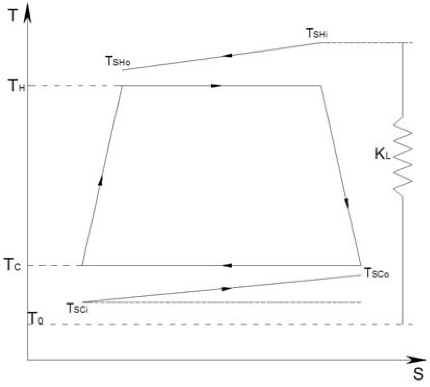
2.1. Thermo-Frigopump Thermodynamical Model

The proposed model represents the steady state regime (hypothesis 1), without heat losses to the ambience (hypothesis 2: adiabaticity of the system) at T0, ambient temperature.
These hypothesis allow us to express the energy and entropy balances as:
Q H + Q C + W =    0
  • Q H < 0 , heat rate transmitted to the hot sink;
  • Q C < 0 , heat rate extracted from the cold source;
  • W > 0 , mechanical (electrical) power given to the cycled fluid.
Figure 1. Finite dimensions model of a Carnot Thermo-frigopump.
Entropy 15 00544 g001
The two heat rates represent the heat utilities, but at different temperature level (TSC < T0 < TSH), quality of the heat.
The entropy balance is expressed, according to entropy analysis:
Q H T H + Q C T C + S i = 0
This balance concerns the cycled fluid. S i is the entropy rate created in the fluid, due to all internal irreversibilities during the cycle. As a first approximation S i is considered a constant here; More detailed representation of S i are possible, and detailed in the recent literature [26].
We restrict the purpose to the case of S i constant, but contrarily to the great majority of papers available in the literature [27], we did not use, the entropy ratio I, nor the heat transfer conductance K method, to represent heat transfer in the heat exchangers HEX. We prefer here, to use the more general method of HEX efficiency ε and NTU, number of heat transfer unit:
N T U = K C min
This global approach of heat transfer in heat exchangers allows to write in the adiabatic case:
Q i = ε i C i min Δ T M A X i
with I = H (or C), and:
Q i =    C i ( T S i i T S i o )
Equation (5) is useful only to calculate TSio, and verify the compatibility of the corresponding value with the conditions at source (TSci > TSco > TC), or sink (TSHi < TSHo < TH).
We suppose here that the limiting fluids in HEX are the external ones, due to internal boiling or condensation. So, equation (4) implies:
Q H = ε H C H ( T S H i T H ) = ε H C H X H
Q C = ε C C C ( T S C i T C ) = ε C C C X C
with C i = m i C P i
Consequently, the finite dimension constraint that appears for HEX concerns their efficiencies according to:
ε H + ε C = ε T 2
Remark: other finite dimensions constraints can be developed, and, the main problem remains how to allocate optimally these dimensions.

2.2. Efficiency Criterions Regarding Thermo-Frigopump

The most popular criterion for reverse cycle machines is the COP, Coefficient Of Performance. It is a first law efficiency criterion. Regarding the Thermo-frigopump it gives:
C O P 1 T F P = Q C Q H W
The combination of (9) and (1) gives:
C O P 1 T F P = Q C    Q H Q C +    Q H
Relation (10) is expressed only with the two useful heat rates (extensities), but they are related by the entropy balance (2) and Equations (6) and (7). So one degree of freedom exists in temperature and the essential fact is that the two useful effects are produced at different levels of temperature.
If we consider simultaneously the quality of heat (temperatures, intensities) and the useful heat rates, the exergy concept appears as the right tool. The only question that remains to be solved is the reference for the temperature potential. The machine, heat source and sink being placed in the ambient environment, it is natural to choose as reference the ambient temperature T0, supposed constant here.
The exergetic COPexS of the system (machine, source and sink) is consequently defined as:
C O P e x S = E x S H + E x S C W
with:
  • E x S H , exergy heat rate transfered to the hot sink according to:
    E x S H = Q H ( 1 T 0 / T ˜ S H ) < 0
  • T ˜ S H , hot sink entropic temperature
  • T ˜ S H = ( T S H 0 T S H i ) / ln ( T S H 0 / T S H i )
  • E x S C , exergy heat rate transfered to the cold source according to:
    E x S C = Q C ( 1 T 0 / T ˜ S C ) < 0
  • T ˜ S C , cold source entropic temperature
  • T ˜ S C = ( T S C 0 T S C i ) ln ( T S C 0 / T S C i )
Using (1), (11), (12), (13) we obtain:
C O P e x S = Q H ( 1 T 0 / T ˜ S H ) + Q C ( 1 T 0 / T ˜ S C ) Q H + Q C
Again, as it has been shown for relation (10), relation (14) has one degree of freedom in temperature.

2.3. Application to Optimization of a Thermo-Frigopump

We propose here to compare Thermo-frigopump efficiencies (10) and (14), respectively the energy and exergy criteria.
The use of the Lagrangian method permits one to construct, the Lagrangian L of the problem as:
L ( T H , T C , ε H , ε C ) = O F ( T H , T C , ε H , ε C ) + λ 1 ( 2 ) + λ 2 ( 8 )
where OF is the Objective Function
The solution satisfies the equations system (16):
L T H = L T C = L ε H = L ε C = L λ 1 = L λ 2 = 0

2.3.1. Case of the Energy Criterion

The objective function OF is given in this case by Formula (10). After some calculation we get the optimum state of the system through:
T H * = T S H i 1 α * / C H
T C * = T S C i 1 + α * / C C
ε H * = ε T C C C H + C C + S i α * ( C H + C C )
ε C * = ε T C H C H + C C S i α * ( C H + C C )
It corresponds to this state vector the optimal COP value, COP1 TFP.
The calculation is straight-forward if we note that α * is given by:
α * = S i ε T
Two important and new results are deduced from these formulas.
First, if the machine is endoreversible ( S i = 0 ) , the value of COP1 TFP* becomes the equilibrium thermodynamics limit, to say:
lim    S i 0    C O P 1 T F P = T S H i + T S C i T S H i T S C i
But [see (19), (20)] at the optimum, heat exchanger efficiencies do not satisfy equipartition, even if the machine is endoreversible. Second, it is possible to continue sequentially the optimization, taking into account the finite dimension of heat source and sink, through C H , C C . Optimal allocation of these heat rates will result, for the external fluids. This optimization is a new one.

2.3.2. Case of the Exergy Criterion

We consider here the exergetic COP as the objective function [see (11, 14)]. The studied system is dependent in a non linear way on temperatures through T ˜ S H , T ˜ S C . So the solution generally is a numerical one.
However, if the temperatures at source and sink are such that:
( T S C i T C ) < < T S C i , | T S H i T H | < < T S H i , it is possible to approximate reasonably, the exergy rates according to:
E x S H ε H C H ( T S H i T H ) ( 1 T 0 T S H i )
E x S C ε C C C ( T S C i T C ) ( 1 T 0 T S C i )
The useful exergy rates are expressed with Carnot factors depending only on parameters T S H i , T S C i .
The optimization method is the same as in Section 2.3.1, and the same equations system to solve is obtained.
To conclude, within the approximation of small temperature differences in heat exchangers, the state vector at the optimum remains (particularly α * does not depend on the type of analysis: the same formula holds for energy or exergy analysis), but the value of the OF at the optimum differs essentially, due to the dependence of the Carnot factor on T0. For the endoreversible system, it is easy to verify, that the optimum COPexS* = 1 (exergetic efficiency) and corresponds to the equilibrium thermodynamics situation.

3. Second Example: The CHP System

Ylmaz [28] has proposed an endoreversible optimization of a Carnot cogeneration system, using a heat transfer conductance model, and an exergetic performance criterion. The model proposed here differs in two ways. First, the more general method of HEX efficiency ε and NTU, number of heat transfer units are used. Second, seeking an upper bound the CHP system is a two temperatures one (and not a three level temperatures model as in [28]). We consider here the common application of Combined Heat and Power System, with two useful effects: heat flux at a temperature level TSCi > T0, and power (mechanical or electrical: W < 0 ) .
This goal could be achieved classically using a vapor direct cycle system (water or ORC, Organic Rankine Cycle). Consequently, the model of the CHP system supposes a fluid boiling at a high temperature level TH, and condensing at a low temperature TC (see Figure 2).
Figure 2. Finite dimension model of a Carnot CHP system.
Entropy 15 00544 g002
This kind of application is common in industry and of major concern now regarding microcogeneration. Here we assume that the machine is functioning according by to the direct cycle represented on Figure 2. This corresponds to a Carnot CHP system, but differs from the one presented recently [28] because we take account here of the finite size of the source and sink, through C H , C C , respectively.

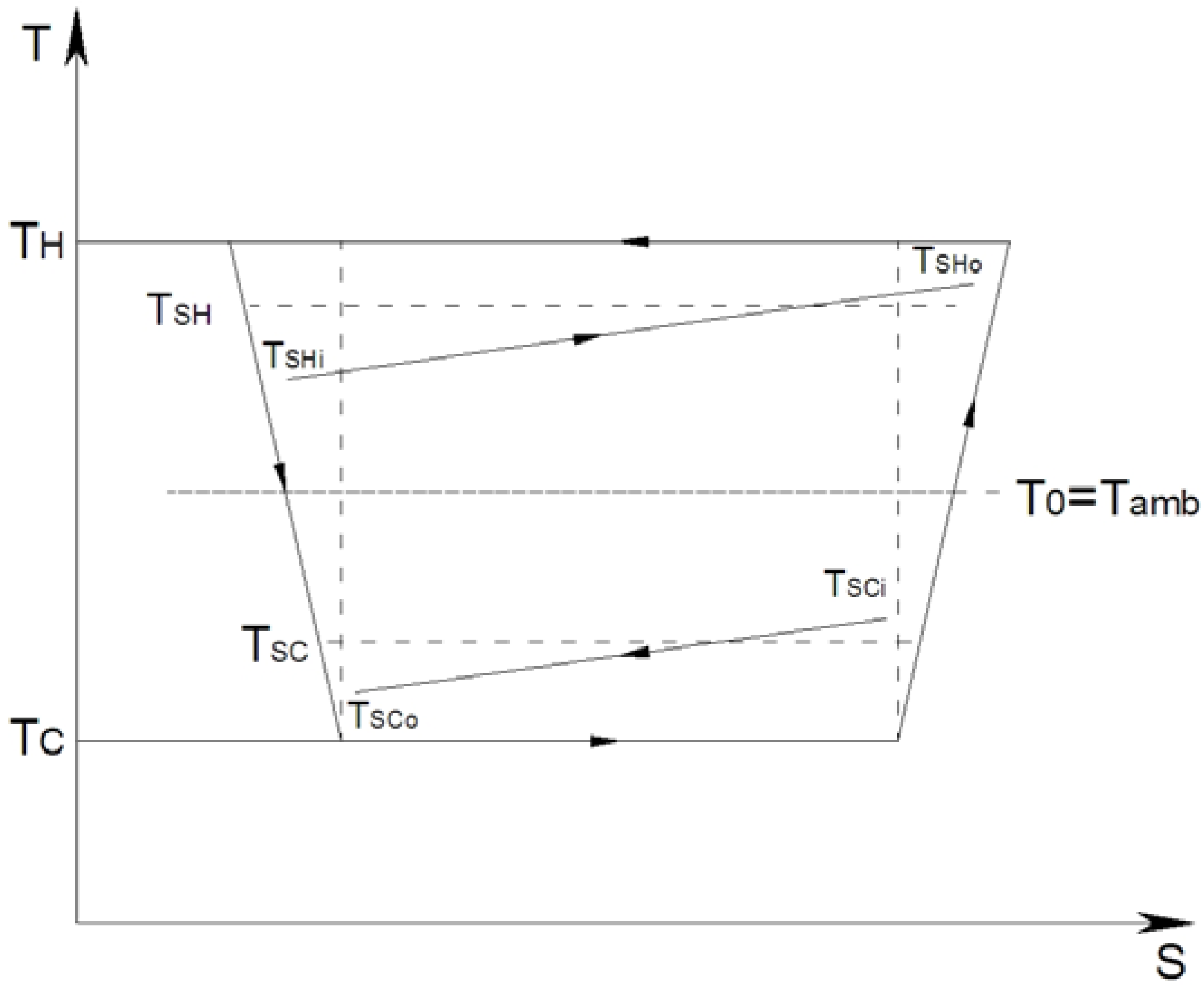
3.1. The CHP Thermodynamical Model

Hypotheses are the same as in Section 2.1. The energy balance (1) remains, but Q H > 0 ,    Q C < 0 ,    W < 0 (again thermodynamical algebraic convention). The entropy balance remains too, and we restrict the purpose to S i constant.
The heat transfer in the HEX are modeled identically too. It results in relations (6, 7), again with the finite size constraint (8).

3.2. Efficiency Criterions Regarding CHP System

The first law criterion η I C H P is defined classically as the ratio of the Usable Energy rate (UE) and the Energy rate Consumption EC (as for Thermo-frigopump):
η I C H P    = W + Q C Q H + Q L
It has been shown in [28] that First Law implies only a "non adiabatic system efficiency" due to the presence of heat transfer loss rate Q L . If the system is adiabatic, the limit of the efficiency is one:
lim    Q L 0 η I C H P = 1
For homogeneity with Section 2, we suppose hereafter an adiabatic CHP Carnot system (without heat loss). The exergetic efficiency differs due to the fact that the quality of heat appears in the Carnot factor according to:
η e x C H P = W + Q C ( 1 T 0 T ˜ S C ) Q H ( 1 T 0 T ˜ S H )
It appears again that the studied system depends in a non linear way of temperatures through T ˜ S H , T ˜ S C , the entropic temperatures. The solution is generally numerical.
However if the temperatures at source and sink are such that:
| T S C i T C | < < T S C i , ( T S J i T H ) < < T S H i , it is possible to approximate reasonably, the exergy rates according to:
E x S C ε C C C ( T S C i T C ) ( 1 T 0 T S C i )
E x S H ε H C H ( T S H i T H ) ( 1 T 0 T S H i )
The heat exchangers exergy rates are expressed with factors depending only on parameters TSHi, TSCi.
Optimization method is the same as in Section 2.3.1, but applied to the following OF (27):
η e x C H P Q H + Q C T 0 T S C i Q H ( 1 T 0 T S H i )

3.3. Some Results Concerning CHP System Exergetic Optimization

The extremum of OF (27) satisfies a set of equations to solve similar to the one obtained in Section 2.3.1 according to:
T H * T S H i 1 + α * / C H
T C * T S C i 1 α * / C C
ε H * ε T C C S i / α * C H + C C
ε C * ε T C H + S i / α * C H + C C
It corresponds to this state vector, the optimal exergetic efficiency, η e x C H P * . The calculation is straightforward with:
α * = S i ε T
In case of an adiabatic system, it appears again that the optimum design of heat exchangers do not satisfy equipartition of efficiencies, even if the system is an endoreversible one.
For the endoreversible situation ( S i = 0 ) , the optimum situation from exergetic point of view gives back the equilibrium thermodynamics limit. The corresponding approximated upperbound is η e x C H P 1 But for the real system (with heat losses and irreversibilities the optimum is well identified and depends on θ H and θ C :
η e x C H P 1 θ H [ 1 C C C H . T S C i T S H i ( 1 θ C ) ( ε T C H + S i ) 2 ( ε T C C S i ) 2 ]
with θ H = 1 T 0 T S H i , θ C = 1 T 0 T S C i
These results gives a more general upperbound for the exergetic efficiency compared to the results given by Erdil [29] and Atmaca et al. [30] due to the fact that finite heat source and sink have been considered here, but without heat leakage (adiabatic case). This will be considered in the future.

4. Generalization and Conclusions

4.1. Generalization

The general problem treated here is to optimize an OF of variables TH, TC, F(TH, TC) with constitutive Equations (1, 2, 6, 7). Equations (6), (7) and (1) allow elimination of intermediate variables Q H , Q C , W . It remains the constraint of entropy balance (2), that possesses one term S i , that is also a function of TH, TC, as has been proved experimentally [31] and also theorically [32], Si = fi(TH, TC) using entropy analysis.
Consequently whatever is the case to solve, the variational calculus method gives after calculations:
T H * = ε H C H T S H i α * F T H f i T H
T C * = ε C C C T S C i α * F T C f i T C
ε H * and ε C * result from the two constraints Equations (2) and (8). The equation to solve for α * becomes:
C H [ ε H C H F ε H F T H ( T S H i T H 2 + f i T H ε H C H ) T S H i T H T H ] = C C [ ε C C C F ε C F T C ( T S C i T C 2 + f i T C ε C C C ) T S C i T C T C ]
FTH, fiTH, FTC, fiTC, F ε H , F ε C are partial derivations with respect to TH, TC, ε H , ε C . The set of equation is adapted to take account of system internal irreversibilities, according to entropy analysis or experimental identifications. The obtained results are not limited to linear heat transfer law, or by the fact that the model imposes to introduce two irreversibility ratios [29,30]. We reiterate that it has been proposed in preceding papers that the entropy analysis method preferable to the ratio method [33,34]. Nevertheless, the endoreversible case is more simple and makes new upper bounds easy to obtain.

4.2. Cases with Added Technical Constraint

If we add to the standard optimization (Section 4.1) one constraint more the degree of freedom in temperature vanishes: it becomes a simulation with temperatures imposed by the design, but we have opportunity to optimize the design (at first regarding variables, ε H , ε C ) with one degree of freedom due to the finite dimension constraint (here(8)). The best allocation for the dimensions could be pursued regarding C H , C C , with a new finite dimension constraint:
C H + C C = C T
This has been done here for CHP systems. The way we develop the model here gives a new upperbound for Carnot CHP system with finite source and sink dimensions:
M A X { M A X [ E x u ] } e n d o = ε T C T 8 [ T S H i T 0 ] 2

5. Conclusions

The present analysis has compared Carnot CHP systems based on Vapor Turbine, and Thermo-frigopump based on vapor compression configurations. They are modeled as thermal machines with finite steady state sources and sinks. Heat transfers are described according to efficiency – NTU method, contrarily to preceding papers. New upper bounds have been proposed and discussed. The performed optimization allows best allocation of efficiencies, and heat rate of the studied systems. The obtained results are sensitive to the chosen criteria. Exergetic criteria are presented as the most relevant ones for multiutilities systems. Generalization of the presented results when technical constraints are added is in due course.

Nomenclature:

C ˙
heat capacity rate [W K−1]
cp
mass specific heat at constant pressure [W kg−1 K−1]
E ˙ X
exergy rate [W]
m ˙
mass flow rate of the working fluid in the cycle [kg s−1]
I
irreversibility ratio
K
heat transfer conductance [W K−1]
NTU
number of heat transfer unit
Q ˙
heat transfer rate [W]
S ˙
entropy rate [W K−1]
T
temperature [K]
t
non dimensional temperature
X
temperature difference [K]
W ˙
mechanical power [W]

Greek symbols

ε
heat exchanger effectiveness
η
efficiency
α
intermediate variable
θ
Carnot factor

Subscripts and superscripts

C
related to the working fluid, at the sink
c
consumed or Carnot
CHP
combined heat and power system
ex
exergetic
H
related to the working fluid, at the source
i
internal
L
loss
SH
source
SC
sink
t
total
U
useful
I
related to first law
0
ambient or imposed value
*
optimal

References

  1. Wakui, T.; Yokoyama, R. Optimal sizing of residential gas engine cogeneration system for power interchange operation from energy-saving viewpoint. Energy 2011, 36, 3816–3824. [Google Scholar] [CrossRef]
  2. Radulescu, M. Combined Electricity and Heat Production Systems with PEMFC or SOFC Fuel Cells and External Vapor Reforming. Ph.D. Thesis, Nancy University, Nancy, France, September 2006. [Google Scholar]
  3. Milia, D.; Sciubba, E. Exergy-based lumped simulation of complex systems: An interactive analysis tool. Energy 2006, 31, 100–111. [Google Scholar] [CrossRef]
  4. Descieux, D. Modelling and Exergetic Comparison of Cogeneration Systems. Ph.D. Thesis, Nancy University, Nancy, France, November 2007. [Google Scholar]
  5. Pehnt, M. Environmental impacts of distributed energy systems—The case of micro cogeneration. Environ. Sci. Policy 2008, 11, 25–37. [Google Scholar] [CrossRef]
  6. Abusoglu, A.; Kanoglu, M. First and second law analysis of diesel engine powered cogeneration systems. Energy Convers. Manag. 2008, 49, 2026–2031. [Google Scholar] [CrossRef]
  7. Zhai, H.; Dai, Y.J.; Wu, J.Y.; Wang, R.Z. Energy and exergy analyses on a novel hybrid solar heating, cooling and power generation system for remote areas. Appl. Energy 2009, 86, 1395–1404. [Google Scholar] [CrossRef]
  8. Abusoglu, A.; Kanoglu, M. Exergoeconomic analysis and optimization of combined heat and power production: A review. Renew. Sustain. Energy Rev. 2009, 13, 2295–2308. [Google Scholar] [CrossRef]
  9. Aussant, C.D.; Fung, A.S.; Ugursal, V.I.; Taherian, H. Residential application of internal combustion engine based cogeneration in cold climate Canada. Energy Build. 2009, 41, 1288–1298. [Google Scholar] [CrossRef]
  10. Nieminen, J.; Dincer, I. Comparative exergy analyses of gasoline and hydrogen fuelled ICEs. Int. J. Hydrogen Energy 2010, 35, 5124–5132. [Google Scholar] [CrossRef]
  11. El-Emam, R.S.; Dincer, I. Energy and exergy analyses of a combined molten carbonate fuel cell—Gas turbine system. Int. J. Hydrogen Energy 2011, 36, 8927–8935. [Google Scholar] [CrossRef]
  12. Bingöl, E.; Kılkış, B.; Eralp, C. Exergy based performance analysis of high efficiency poly-generation systems for sustainable building applications. Energy Build. 2011, 43, 3074–3081. [Google Scholar] [CrossRef]
  13. Doluweera, G.H.; Jordaan, S.M.; Moore, M.C.; Keith, D.W.; Bergerson, J.A. Evaluating the role of cogeneration for carbon management in Alberta. Energy Policy 2011, 39, 7963–7974. [Google Scholar] [CrossRef]
  14. Barelli, L.; Bidini, G.; Gallorini, F.; Ottaviano, A. An energetic–Exergetic comparison between PEMFC and SOFC-based micro-CHP systems. Int. J. Hydrogen Energy 2011, 36, 3206–3214. [Google Scholar] [CrossRef]
  15. Ji, J.; Liu, K.; Chow, T.T.; Pei, G.; He, H. Thermal Analysis of PV/T Evaporator of A Solar Assisted Heat Pump. Int. J. Energy Res. 2007, 31, 525–545. [Google Scholar] [CrossRef]
  16. Thilak Raj, N.; Iniyan, S.; Goic, R. A review of renewable energy based cogeneration technologies. Renew. Sustain. Energy Rev. 2011, 15, 3640–3648. [Google Scholar]
  17. Ibrahim, A.; Othman, M.Y.; Ruslan, M.H.; Mat, S.; Sopian, K. Recent advances in flat plate photovoltaic/thermal (PV/T) solar collectors. Renew. Sustain. Energy Rev. 2011, 15, 352–365. [Google Scholar] [CrossRef]
  18. Obernberger, I.; Carlsen, H.; Biedermann, F. State of the Art and Future Developments Regarding Small Scale Biomass CHP Systems with a Special Focus on ORC and Stirling Engine Technologies. In Proceedings of the 2003 International Nordic Bioenergy Conference, Jyväskylä, Finland, 2–5 September 2003.
  19. Uddin, S.N.; Barreto, L. Biomass-fired cogeneration systems with CO2 capture and storage. Renew. Energy 2007, 32, 1006–1019. [Google Scholar] [CrossRef]
  20. Zhang, X.; Su, S.; Chen, J.; Zhao, Y.; Brandon, N. A new analytical approach to evaluate and optimize the performance of an irreversible solid oxide fuel cell-gas turbine hybrid system. Int. J. Hydrogen Energy 2011, 36, 15304–15312. [Google Scholar] [CrossRef]
  21. Vuillecard, C.; Hubert, C.E.; Contreau, R.; Mazzenga, A.; Stabat, P.; Adnot, J. Small scale impact of gas technologies on electric load management—μCHP & hybrid heat pump. Energy 2011, 36, 2912–2923. [Google Scholar]
  22. Lowe, R. Combined heat and power considered as a virtual steam cycle heat pump. Energy Policy 2011, 39, 5528–5534. [Google Scholar] [CrossRef]
  23. Wang, J.J.; Jing, Y.Y.; Zhang, C.F. Weighting Methodologies in Multicriteria Evaluations of CHP Systems. Int. J. Energy Res. 2009, 33, 1023–1039. [Google Scholar] [CrossRef]
  24. Chua, K.J.; Yang, W.M.; Wong, T.Z.; Ho, C.A. Integrating renewable energy technologies to support building trigeneration—A multi-criteria analysis. Renew. Energy 2012, 41, 358–367. [Google Scholar] [CrossRef]
  25. Rubio-Maya, C.; Uche-Marcuello, J.; Martínez-Gracia, A.; Bayod-Rújula, A.A. Design optimization of a polygeneration plant fuelled by natural gas and renewable energy sources. Appl. Energy 2011, 88, 449–457. [Google Scholar] [CrossRef]
  26. Feidt, M.; Costea, M.; Petre, C.; Petrescu, S. Optimization of Direct Carnot Cycle. Appl. Therm. Eng. 2007, 27, 829–839. [Google Scholar] [CrossRef]
  27. Feidt, M. Thermodynamics applied to reverse cycle machines, a review. Int. J. Refrig. 2010, 33, 1327–1342. [Google Scholar] [CrossRef]
  28. Ilmaz, T. Optimization of cogeneration systems under alternative performance criteria. Energy Convers. Manage. 2004, 45, 939–945. [Google Scholar] [CrossRef]
  29. Erdil, A. Exergy optimization for an irreversible combined cogeneration cycle. J. Energy Inst. 2005, 78, 27–30. [Google Scholar] [CrossRef]
  30. Atmaca, M.; Gumus, M.; Inan, A.T.; Yilmaz, T. Optimization of irreversible cogeneration systems under alternative performance criteria. Int. J. Thermophys. 2009, 30, 1724–1732. [Google Scholar] [CrossRef]
  31. Feidt, M.; Costea, M. Energy and exergy analysis and optimization of combined heat and power systems. Energies 2012, 5, 3701–3722. [Google Scholar] [CrossRef]
  32. Petre, C.; Feidt, M.; Costea, M.; Petrescu, S. A model for study and optimization of real-operating refrigeration machines. Int. J. Energy Res. 2009, 33, 173–179. [Google Scholar] [CrossRef]
  33. Feidt, M. Reconsideration of criteria and modelling in order to optimize the efficiency of irreversible thermomechanical heat engines. Entropy 2010, 12, 2470–2484. [Google Scholar] [CrossRef]
  34. Feidt, M. Optimal thermodynamics new upperbounds. Entropy 2009, 11, 529–547. [Google Scholar] [CrossRef]

