
Polymer Bead Foams: A Review on Foam Preparation, Molding, and Interbead Bonding Mechanism


1
School of Materials Science and Engineering, Sun Yat-sen University, Guangzhou 510275, China
2
Nanchang Research Institute, Sun Yat-Sen University, Nanchang 330224, China
*
Author to whom correspondence should be addressed.
Macromol 2023, 3(4), 782-804; https://doi.org/10.3390/macromol3040045
Submission received: 30 August 2023
/
Revised: 23 November 2023
/
Accepted: 28 November 2023
/
Published: 1 December 2023
Abstract
:The diverse physical appearances and wide density range of polymer bead foams offer immense potential in various applications and future advancements. The multiscale and multilevel structural features of bead foams involve many fundamental scientific topics. This review presents a comprehensive overview of recent progress in the preparation and molding techniques of bead foams. Firstly, it gives a comparative analysis on the bead foam characteristics of distinct polymers. Then, a summary and comparison of molding techniques employed for fabricating bead foam parts are provided. Beyond traditional methods like steam-chest molding (SCM) and adhesive-assisted molding (AAM), emerging techniques like in-mold foaming and molding (IMFM) and microwave selective sintering (MSS) are highlighted. Lastly, the bonding mechanisms behind these diverse molding methods are discussed.
1. Introduction
Physical foaming with carbon dioxide (CO2) or nitrogen (N2) as foaming agents produces no harmful residues, making it friendly to the environment [1,2]. Therefore, the fabrication of polymer foams by physical foaming has received increasing attention. Polymer foams can be categorized into bead foams/foamed beads, foamed sheets, foamed boards, and foamed profiles based on the product shape [3]. For bead foams, the structural design of the mold allows the production of bead foam parts with complex shapes and rich appearance patterns [4]. Since the introduction of expandable polystyrene (EPS) around 1950, new categories of bead foams have been continuously developed to meet higher requirements, especially after 2000. With low density and rich shapes, bead foam parts have found extensive applications in various fields, including cold chain logistics, goods packaging, sports protection, and automotive interiors.
Figure 1 illustrates the multiscale and multilevel structure of bead foams ranging from nanometers to centimeters. Each scale of the structure is associated with various research topics. From the perspective of molecular chains, the variety of bead foams has expanded from the initial PS [5,6] to polyethylene (PE) [7], polypropylene (PP) [8,9,10,11], thermoplastic polyurethane (TPU) [3,12,13,14], polylactic acid (PLA) [15], and other polymers. The selection of the regulatory strategy for foaming is based on the specific chain structure. For instance, PP foaming is adopted primarily according to the regulating crystalline structure and melt strength. The microcellular structure of foamed beads influences the moldability and mechanical properties of the final products. Therefore, the desired cell morphology, including cell size, cell density, and open cell content, is critical to the preparation of bead foams. Bead foams can be classified into two categories: (1) expandable particles containing volatile gases, represented by EPS, and (2) expanded/foamed beads, generally prepared by autoclave foaming. Autoclave foaming involves filling polymer pellets into an autoclave, which are then saturated with high-temperature and high-pressure gas. During the saturation stage, the gas diffuses into the polymer and exerts effects on the condensed structure of the polymer chains. In general, water is used as a dispersion medium to ensure the uniform heating of pellets and prevent conglomeration. To improve production efficiency, anhydrous autoclave foaming has been developed and implemented in the production of expanded TPU (ETPU) beads. Furthermore, the production of bead foams can also be achieved through extrusion foaming, where it is crucial to equip an appropriate granulation unit [9,16]. Compared to autoclave foaming, bead foams prepared through extrusion foaming suffer from lower cell uniformity and higher open-cell content [17,18]. Nonetheless, the process continuity and high production stability have made extrusion foaming the most promising method for bead foam production in the future.
Bead foams, which are rarely used directly, need to be molded into bead foam parts to maximize their benefits. The appearance quality and bonding strength between beads, which directly affect the application of the molded parts, are the main indicators for evaluation of the molding effect [19]. Through the design of the mold surface, plentiful appearance patterns are available for the parts. Steam-chest molding (SCM) is one of the most important and widely utilized molding methods for bead foams. During the SCM process, foamed beads are injected into the mold while saturated steam is employed as the heating medium to soften the beads and induce interbead bonding. It is crucial to achieve sufficient interbead bonding while maintaining a stable cell structure for the molding process. It has been suggested that the sintering of bead foams is closely related to their thermal properties. Inspired by SCM, various methods for molding bead foams have been developed, such as adhesive-assisted molding (AAM) [20,21,22], in-mold foaming and molding (IMFM) [23], microwave selective sintering (MSS) [24,25], etc. Nevertheless, the molding mechanisms behind these methods are seldom discussed and compared systematically.
This article presents a systematic overview of the recent research progress on bead foams, covering the preparation and molding methods of beads. In particular, the common issues involved in the bead foam molding process and the molding mechanism are discussed. Hence, this review could provide theoretical guidance for the development of new bead foam types.
2. Preparation of Bead Foams
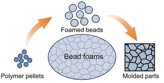
Typically, the fabrication of bead foam parts consists of two steps: preparing foamed beads/bead foams and molding these bead foams into final parts. As shown in Figure 2, the preparation of bead foams is mainly carried out by autoclave foaming and extrusion foaming. Autoclave foaming is a batch process during which polymer pellets are saturated with high pressure gas under temperatures lower than their melting point, and foaming occurs upon rapid depressurization [3,26]. By comparison, extrusion foaming is a continuous process to prepare bead foams in which an additional granulator system is required [9,10,18].
The properties of the polymer itself play a critical role in the production of bead foams. Specifically, crystallization properties, melt strength, the modification of molecular chains (such as grafting and blending), and the interaction with saturated gases all have a significant impact on the foaming behavior. Therefore, different strategies are necessary for various polymers to obtain bead foams with the desired properties. In the following sections, the preparation of bead foams based on different polymers will be discussed.
2.1. Expandable Polystyrene (EPS) Beads
EPS foams account for the largest share in the bead foam market. The development of EPS started in 1949 when chemist Fritz Stastny at BASF successfully produced this material in the laboratory. Generally, a blowing agent (usually pentane) with a proportion of 4–7 wt% is introduced in the PS suspension polymerization process to produce EPS beads. Under normal circumstances, EPS beads, in the form of small grains, cannot be used alone. These EPS beads need to be pre-expanded and molded into final parts with various geometries [27]. The molded parts produced from EPS beads have the advantages of excellent thermal insulation, low density, low moisture absorption, and low cost. Additionally, the production process of EPS is simple. Due to these strengths, EPS parts are widely used in various fields, such as packing, building insulation [6], transportation, and flotation foams. However, the intrinsic flammable feature of EPS prevents it from being directly used in some specific fields, such as building insulation [6,28,29]. In view of this, research on EPS has focused mainly on adding multifunctionality, particularly the flame-retardant property, to EPS using a variety of methods.
The addition of various fillers in the polymerization process has been demonstrated as an effective method for manufacturing multifunctional EPS beads. Recently, hydrophobic Fe3O4 was incorporated into EPS by means of in situ suspension polymerization of styrene (Figure 3) [5]. The researchers systematically explored the effects of different experimental variables, such as Fe3O4 content, stirring speed, and the amount of surfactant, on the size and magnetism of expandable PS/Fe3O4 beads. SEM and energy-dispersive spectrometer results showed that Fe3O4 was well dispersed in the synthesized colorized and magnetic beads. It was concluded that the bead size and size distribution as well as the degree of color could be adjusted by altering the Fe3O4 content. In addition, flame retardants, such as aluminum hydroxide, ammonium polyphosphate, and magnesium hydroxide, can be coated onto the surface of EPS beads or incorporated into PS chains via suspension polymerization. Hong et al. [30] used methylene diphenyl diisocyanate (MDI) as the binding agent to improve compatibility between the intumescent flame retardant and EPS beads. The cone calorimeter tests showed that the parts made of MDI-coated flame-retarded EPS exhibited good flame resistance. By incorporating flame retardants into EPS through in situ polymerization, Bai et al. [29] prepared halogen-free flame-retarded EPS beads. The results showed that the fire retardant, namely, hexaphenoxycyclotriphosphazene (HPCTP), was uniformly dispersed in the PS matrix at nanoscale; the particles formed by HPCTP were of the order of 33–57 nm, with an average diameter of 44.86 nm. Also, the mechanism of flame retardancy was proposed based on the microscale combustion calorimetry results. In addition, it was found that fillers could be deposited on the surface of EPS beads. Lelis et al. [31] prepared SiO2-coated EPS beads by physical vapor deposition, and the EPS beads were then pre-expanded and molded into EPS parts. When coated with SiO2 additives, the expanded PS demonstrated an almost 10% decrease in moisture adsorption and an 8.4% increase in deformation resistance. Surprisingly, the molded parts also showed enhanced interbead bonding strength, which could be attributed to the binding effect of SiO2.
2.2. Expanded Polypropylene (EPP) Beads
EPP has attracted much attention since its invention in the 1980s. EPP parts molded from foamed beads show excellent performance in solvent resistance, impact resistance, heat resistance, and energy absorption capacity. EPP beads are typically fabricated by autoclave foaming, and their foaming temperature window is very narrow due to the high crystallinity and low melt strength. The destruction of PP crystals during autoclave foaming results in a significant reduction in melt strength, making it challenging to prepare EPP beads with the desired properties [32]. In view of this, it is necessary to improve the foaming behavior and reduce the processing difficulty through copolymerization with α-olefin or molecular modification [11,33,34]. Furthermore, the crystalline structures of PP are sensitive to foaming conditions, such as temperature profile, gas type and pressure, and saturation time. Therefore, the foaming process should be carefully adjusted to achieve the expected foaming results.
Park et al. [35] studied the foaming behavior of EPP beads using CO2 as the blowing agent in a lab-scale autoclave and systematically discussed the critical processing variables for EPP bead production. It was found that an optimum stirring speed, dependent on the shape of the stirring propeller and channel sizes, was necessary for a uniform distribution of PP pellets in the dispersing media. Meanwhile, it was found that die geometry and saturation pressure are key to the pore morphology and thermal properties of EPP beads. When the pressure increased from 3.8 to 5.5 MPa, the cell density increased by nearly one order of magnitude and the expansion ratio increased from 3.4 to 16.4 times. In another study conducted by the same group, Nofar et al. [36] explored the effect of various foaming parameters on the formation of double melting peaks in EPP beads with the help of a high-pressure DSC. It was demonstrated that the thermal properties of PP samples were strongly affected by the saturation temperature and pressure; an increase in saturation temperature in an appropriate range facilitated the crystal perfection to form a higher melting peak (Tm-high), while the melted crystals formed a lower melting peak (Tm-low) during the cooling stage. Similarly, Guo et al. [37] also demonstrated that the double melting peak temperature in EPP beads increased with an increase in saturation temperature and pressure and that the formation of a double melting peak in EPP beads was helpful to the sintering of foamed beads.
To improve the foamability of linear PP, several methods have been employed for increasing the expansion ratio or optimizing the cellular structure, including copolymerization, blending, and modification (like grafting and cross-linking). It has been proven that the type and content of comonomer in PP copolymers have a significant influence on the foaming behavior of EPP beads [32]. Park et al. [32] used a pilot autoclave to identify differences in the foaming behavior of a linear PP and PP copolymers containing ethylene comonomer. They reported that the addition of 3.5 wt% ethylene comonomer could reduce the crystallinity and melting temperature (Tm) of PP resin, thus improving PP foamability and increasing the cell size. By blending 3–8 wt% PP with a high melting point, Hu et al. [38] found that the cellular morphology and melting properties of EPP beads based on PP with a low melting point could be improved. Guo et al. [34] fabricated high melt strength polypropylene (HMSPP) by direct polymerization and discussed the impact of melt strength on the cellular morphology and properties of EPP beads obtained through autoclave foaming. They found that the EPP beads prepared from HMSPP had more uniform and well-distributed cells than those from the polypropylene homopolymer. Janani et al. [39] investigated the role of polymorphism in the production of EPP bead foams with a double melting point and concluded that the utilization of polymorphism during solid-state foaming is feasible for the preparation of EPP beads with nanosized cells.
At present, it is a trend to reduce energy consumption in the preparation of bead foams. Therefore, strategies such as blending PP with various polyolefin components or copolymerizing propylene with other short-chain alkene have been utilized to fabricate EPP beads with moderate foaming conditions. Lyu et al. [11] synthesized various ethylene–propylene–butene-1 ternary copolymers (TPPs) and ethylene–propylene copolymers and investigated the autoclave foaming behavior of these copolymers. It was found that with the addition of 1-butene, the saturation temperature for TPPs could be reduced by 5 °C with the expansion ratio of EPP beads remaining unchanged. Huang et al. [40] found that the temperature and pressure could be reduced by blending a certain amount of polyputene-1 (PB-1) during the autoclave foaming of EPP beads without compromising the expansion ratio. With a lower foaming temperature and a higher expansion ratio, the production energy consumption can be reduced, which enhances the competitiveness of EPP foams.
Despite a large amount of research on the extrusion foaming of PP, these studies mainly focused on the preparation of foamed strands and did not study foamed beads [16,33,41,42,43,44]. Recently, Huang et al. [10] successfully manufactured EPP beads by a commercially available extrusion line equipped with a self-designed wind cutting tool. They studied the growth of cells after the foam exited the extruder die using a high-definition camera. As shown in Figure 4, EPP beads with various shapes and sizes could be easily produced by adjusting the pelletizing speed. The obtained foamed beads had the lowest density of 0.052 g/cm3, and the open-cell content of the beads was higher than 50%. In another work on extrusion foaming, Huang et al. [9] improved the cell uniformity of EPP beads by blending 10 wt% TPU resin. They found that more uniform cell morphology contributed to better mechanical strength of the EPP molded parts. With the help of a foam extrusion line designed by Sulzer, Tammaro et al. [8] produced EPP beads with a bulk density ranging from 20 to 100 g/cm3 using a long-chain branched HMSPP as the feedstock and CO2 and isobutane as the blowing agents. It was proposed that the strain hardening feature of HMSPP could make it easier to produce EPP beads with a lower open-cell content.
Generally, EPP beads produced through autoclave foaming display closed and uniform cell structures. However, the beads prepared by the extrusion foaming process exhibit a higher content of open cells with less uniformity. Therefore, it is of significance to achieve highly uniform and closed cells in the extrusion foaming process.
2.3. Expanded Thermoplastic Polyurethane (ETPU) Beads
TPU, a category of TPE, is composed of soft and hard segments. Oligomer diols with low glass transition temperature (Tg), such as poly(tetramethylene glycol) [45], act as soft segments, which endow TPU with excellent stretchability and elasticity. ETPU beads with pore structures exhibit many advantageous properties, including low density, high resilience, and cushioning effect [13,14]. A lot of research has focused on elucidating the relationship between TPU molecular chains’ structure and foaming behavior, strategies for suppressing the shrinkage of the foamed beads, and adjustment of the foaming process [46,47].
The foaming behavior of ETPU beads is closely related to the chemical structure, composition ratio, and molecular weight of the hard and soft segments in TPU. Nofar et al. [48] investigated the effects of hard segment content on the foaming behaviors of TPU pellets. When the hard segment content in the TPU resins was 39, 49, and 57 wt%, the corresponding Shore hardness of these pellets was 29, 46, and 64D, respectively. It was found that ordered structures with higher perfection could form in TPU with higher hard segment content, thus leading to higher melting temperatures. An increase in the hardness could broaden the foaming temperature window and increase the suitable foaming temperature. For TPU with the highest hardness, 64D TPU exhibited the lowest shrinkage ratio, but the expansion ratios of the foamed samples were lower than 3 times. Furthermore, they compared the foaming behavior of TPUs with similar hard segments but different soft segments (polyester and polyether) [49]. Compared to polyether-based TPU, polyester-based TPU showed a wider foaming temperature window. When the temperature increased from 85 to 115 °C, the polyether-based TPU formed larger and more closely packed microcrystalline under supercritical CO2 conditions, which might hinder the growth of the nucleated cells and lead to a limited expansion ratio of the foamed beads. Additionally, the effects of thermal annealing and pressure drop rate on the foaming behavior were explored. In another study, Nofar et al. [50] further investigated the impact of different soft segment molecular weights (1000, 2000, and 3500 g/mol) on the foaming performance of TPU pellets. It was found that an increase in soft segment molecular weight reduced the Tg of the soft segments, promoted the formation of wide ordered hard segment aggregation, and led to a broader melting range and wider foaming temperature window. It was also observed that increasing the length of soft segments could not only facilitate the expansion of the bead foams but also enhance the crystallization of the hard segments, thereby promoting heterogeneous cell nucleation and reducing the shrinkage of the foamed samples (Figure 5).
Based on the theory that hard domains can act as heterogeneous nucleating agents, it was argued that the adjustment of the cellular morphology of TPE foams can be realized by changing the degree of ordering of the hard segments [51,52,53,54]. Park et al. found that a large amount of less-ordered hard segment microcrystallites in TPU induced by glycerol monostearate and high-pressure butane could promote cell nucleation and thus increase the cell density [52]. A similar result was also observed in PEBA foams by the same group [53].
The formation of cellular structures in polymers requires enhanced molecular mobility at elevated temperatures. Jiang et al. [4] defined the “high-elastic state” of TPU by softening temperature (Ts) and viscous flow temperature (Tv) and associated the molecular movement with the autoclave foaming behavior of TPU pellets. In the “high-elastic state”, the polymer chain motion was significantly enhanced, and large deformation of the entire molecular chain was possible. Within this state, the low-ordered hard segments were disassociated and mixed into the soft segment domains, while part of the hard segments were rearranged into more closely-packed structures. The hard segments of different orders acted as nucleation sites to promote cell nucleation, and the nucleated cells could expand largely under the “high-elastic state”. The soft segment chains were significantly stretched, and some of the hard segments were dissociated and rearranged, eventually leading to the formation of cell structures. ETPU beads with a high expansion ratio were obtained within the temperature range defined as the “high-elastic state” (Figure 6A). Another study conducted by Jiang et al. [51] demonstrated that the proposed “high-elastic state” could also be used to explain the autoclave foaming behavior of EPEBA beads (Figure 6B).
Postfoaming shrinkage is a common phenomenon in TPE physical foaming, and the shrinkage mechanism has been widely discussed [1,55,56]. On the one hand, the rate at which gas diffuses out of the cells is much faster than the rate at which the air diffuses into the cells, creating a negative pressure in the pores. On the other hand, the cell walls of TPE foams with a low modulus cannot resist the compressive force generated by negative pressure. Figure 7 shows the shrinkage behavior of ETPU beads obtained over a wide range of foaming temperatures. After foaming, the expansion ratios of the ETPU beads were very high, even higher than 25 times. However, these foamed beads will shrink seriously with the gas diffusing out of the cells. When the air fully diffuses into the cells, the shrunk beads will “expand” again to a certain degree. To reduce the shrinkage ratio of TPE foams, strategies such as blending with plastics [57,58], using chemical cross-linking [59], using gas mixture as blowing agent [46,47], and compounding with fillers [60,61] have been proposed. A detailed discussion can be found in the review on the physical foaming of TPE [1].
2.4. Expanded Polylactic Acid (EPLA) Beads
PLA, a biodegradable plastic synthesized from biological resources, is widely used in food packaging and biomedicine due to its good biodegradability and biocompatibility. Therefore, PLA is considered as an ideal alternative to petroleum-based plastics to address the growing problem of plastic pollution. Currently, a great deal of research has been devoted to the production of PLA foams by physical foaming. The introduction of cellular structure can not only make PLA lightweight without affecting its biocompatibility but also accelerate the degradation rate of PLA foams [62].
EPLA beads are mainly produced using autoclave foaming. It has been proven that crystal structure [63], molecular weight [64], and molecular architecture play a vital role in the autoclave foaming process of EPLA beads [65]. With low melt strength, PLA suffers from low foamability. However, studies have proven that chemical modification can effectively improve the foamability of PLA. Altstädt et al. [64] incorporated various chemical modifiers into PLA by reactive extrusion using a twin-screw extruder. It was found that the modified PLA exhibited higher molecular weight and reduced crystallinity. The incorporation of organic peroxide and multifunctional epoxide resulted in the most significant increase in the molecular weight and polydispersity of PLA. Under the foaming conditions of 157 °C/0.5 h/18 MPa, all the densities of the modified PLA foams were reduced, with a low density of 107 kg/cm3. An increase in the extensional viscosity of modified PLA also led to larger cells because the cells had more time to expand before cell coalescence. Using a long-chain branched PLA, Park et al. [63] investigated the formation of double melting peaks in PLA bead foams. They found that high-pressure CO2 saturation could dramatically affect the crystal structure of PLA, thus altering the cellular morphology of PLA foams. On the one hand, during the high-pressure CO2 saturation process, the formation of a small number of perfected crystals with large size would increase the high melting temperature. On the other hand, the foaming and cooling steps would destroy parts of the crystals and induce the formation of the low melting peak. Additionally, Ruckdäschel et al. [66] studied the influence of different saturation conditions on the density and cell morphology of amorphous PLA. It was reported that the initial pressure drop rate had a dramatic influence on the nucleation density and that the desirable cell morphology could be obtained by selective modification of foaming conditions.
As a biopolymer, PLA is highly susceptible to hydrolytic degradation, especially under the high-pressure CO2 saturation process during autoclave foaming. Under the saturation of 120 °C/5.5 MPa/15 min, Park et al. found that Mw decreased from 360 kg/mol for raw pellets to about 305 kg/mol for EPLA beads [67]. When the saturation temperature was gradually increased to 126 °C, more hydrolysis occurred, and the Mw of the foamed sample was slowly reduced to about 285 kg/mol (Figure 8). The hydrolysis of PLA is sensitive to the saturation time. Under the saturation of 120 °C/5.5 MPa, it was observed that Mw was dramatically reduced from 300 to 160 kg/mol with the saturation time extending from 15 to 60 min. These results suggest that the saturation condition should be properly selected to control the extent of hydrolysis to produce EPLA beads with the desired cellular morphology and expansion ratio. By compounding PLA with a hydrolysis stabilizer via reactive extrusion, Bonten et al. [26] found that the hydrolysis of PLA during autoclave foaming can be markedly suppressed without compromising the foamability of EPLA beads.
EPLA beads can also be prepared through extrusion foaming. Using supercritical CO2 extrusion foaming equipped with a wind-cooling pelletizing unit, Huang et al. [15] produced EPLA beads with a maximum expansion ratio of 20-fold. In this study, PLA had been modified with a chain extender to induce the formation of a branching structure, therefore improving the foamability of PLA.
2.5. Bead Foams Based on Other Polymers
Although bead foams of the aforementioned polymer types prevail in the market, they pose issues of limited-use temperature and mechanical strength. In contrast, bead foams prepared from engineering plastics exhibit superior temperature resistance and mechanical strength, thus receiving much attention in recent years. Various engineering polymers, including poly(ether imide) (PEI) [20,68], polyamide (PA) [69,70], polybutylene terephthalate (PBT) [11,71], and polycarbonate (PC) [72,73], have been employed in the production of bead foams.
3. Molding of Bead Foams
Individual foamed beads typically need to be molded into three-dimensional parts through a molding process during which it is of great importance to keep the integrity of the cell structure and ensure sufficient interbead bonding strength. The bead foams in the molded parts must have sufficient welding strength to prevent the beads from falling off during use. According to the different welding mechanisms of bead foams, the molding methods can be divided into steam-chest molding (SCM), adhesive-assisted molding (AAM), in-mold foaming and molding (IMFM), and microwave selective sintering (MSS).
3.1. Steam-Chest Molding (SCM)
Steam-chest molding (SCM), first used to produce EPS parts, is an important bead foam molding technology. It is of high production efficiency and has the ability to produce large-sized products [3,14,67,74]. The wide adjustable temperature range and high latent heat of the saturated steam can ensure rapid heating of the foamed beads. Using high pressure saturated steam as a heat transfer medium, the foamed beads in SCM are heated and softened, thus realizing the interfacial diffusion and entanglement of molecular chains between the beads under huge compression force. In this way, the single bead foams become molded parts with complex geometry after SCM.
The main equipment involved in SCM include a steam generator, a feed system, and an SCM machine. The molding process of the bead foams is realized in the SCM machine. The detailed description of SCM can be found in the literature [65,75]. As depicted in Figure 9, the whole molding cycle can be divided into several steps.
I. The movable mold is shifted and closed. At this stage, a certain gap is maintained according to the final thickness of the products. Foamed beads are injected into the mold to fill the cavity, and the mold is then closed at the final position.
II. The high-pressure saturated steam enters the mold cavity through the gas nozzles to heat the foamed beads. To obtain a uniform temperature profile, the steam is usually introduced in the following order: (1) double-sided preheating, (2) cross-steam from the fixed mold and then from the movable mold, (3) simultaneous steaming from the double molds (Figure 9c–e). Steam pressure and steaming time are the key parameters during this process. In the heating step, the formation of bonding between adjacent beads determines the mechanical properties of the final parts.
III. Cool water is sprayed onto the mold surface to cool the mold and the molded parts. Cooling can freeze the molecular chains that diffuse and entangle in the welded interface and eliminate the adverse effect of high temperature on the cell structure and the dimensional stability of the product [76]. After cooling, compressed air is then used to blow off the condensation water, and most of the remaining water is removed by vacuum.
IV. The molds open, and the molded part is ejected. Thus, the molding process is completed.
In addition to conventional EPS [6] and EPP [8,9,11,40,77], SCM can also be used to mold ETPU [3,14] and EPLA [67] parts and even to produce engineering plastic molded parts, such as EPC and expanded polybutylene terephthalate (EPBT) parts [72,74]. As an amorphous polymer, the Tg of PS is around 100 °C and the temperature of saturated steam used to mold EPS beads is in the range of 107–120 °C. The molding temperature of EPP beads is usually in the range of 120–150 °C, which is dependent on the molecular chain structure and the expansion ratio of EPP foamed beads [9,11,40,78]. Zhai et al. [14] molded ETPU beads with different bead densities (e.g., 0.24, 0.29, and 0.35 g/cm3) and investigated the molding behavior of the beads and the mechanical performance of ETPU parts, with the molding temperature being 135.7 °C. They found that all the beads had good interbead bonding, and the tensile strength of the molded part was increased from 0.91 MPa to 1.80 MPa. Accompanying this increase in tensile strength was an increase in the elongation at break of the parts from 163.1% to 360.1%. Additionally, the ETPU parts showed excellent deformation recovery ability. The ETPU cell structure remained stable after 200 compression cycles at 60% compressive strain. In a more recent study, Jiang et al. [51] prepared EPEBA parts using two types of foamed beads with different hardness values, and the EPEBA parts showed a low density of less than 0.15 g/cm3 and a high resilience of above 70%.
A large amount of research has been conducted by Altstädt et al. to prepare bead foam parts based on engineering materials [17,70,72,74,79,80]. They produced EPBT beads by extrusion foaming with the help of an underwater granulator [79]. It was found that EPBT beads with finer cell morphology and lower density can be obtained by incorporating a chain extender. They used an SCM machine with a customized steam generator to weld the foamed beads, with the steam temperature being in the range of 192–205 °C. It was found that the pure EPBT beads could not be molded; however, the chemically modified EPBT beads could be welded into final parts. The EPBT parts showed the lowest density of 167 kg/m3 and excellent thermal stability under compression. Using similar processing techniques, they also prepared expanded polyamide-12 bead foams [70] and expanded polycarbonate [72].
By now, SCM has been utilized for over 70 years. Both academia and industry are concerned about how to reduce the energy consumption of the molding process, improve the molding efficiency, and improve the welding strength of the bead foams. Aiming to reduce the temperature variation among the beads during the molding process, Hossieny et al. [81] introduced hot air as a second heat transfer medium in the steam line. Because hot air has a low Joule–Thompson coefficient, using a mixture of heating media can improve the surface quality and enhance the tensile strength of the molded EPP parts. As a result, the steaming time was reduced by approximately 32%, and the molding temperature decreased by 16 °C. The results reveal that a certain amount of hot air in combination with saturated steam during the molding process can increase molding efficiency and reduce energy consumption.
3.2. Adhesive-Assisted Molding (AAM)
Adhesive-assisted molding (AAM) involves coating foamed beads with a particular adhesive, filling the coated beads into a mold and finally solidifying the adhesive to produce bead foam parts. Provided appropriate adhesive and curing process selection, the use of AAM is possible with all types of foamed beads. In a traditional SCM machine, welding engineering plastic bead foams with high Tm or Tg is a challenging task. Nonetheless, AAM has been demonstrated as a viable method to produce molded parts using foamed beads made of engineering plastic. Jiang et al. [20] prepared expanded poly(ether imide) (EPEI) parts using epoxy resin as the interbead bonding material. EPEI bead foams with an expansion ratio of 30–56 times were obtained by temperature-rising foaming, with CO2/acetone as the mixed foaming agent. As illustrated in Figure 10A, EPEI beads were coated with epoxy resin and then filled into a mold cavity, and the bonding layers were finally cured by heat compression to produce molded EPEI products. The obtained EPEI parts had a low density of 80–200 kg/m3 and showed high thermal stability at 160 °C and superior flame-retardant abilities. In recent works [21,22], flexible EPEBA parts have been fabricated by AAM (Figure 10B).
AAM can be easily scaled up to an industrial scale. In addition, AAM can produce molded parts with complex geometry and a large size. For bead foams that cannot be welded by conventional SCM, AAM can also provide feasible approaches.
3.3. In-Mold Foaming and Molding (IMFM)
Recently, some attempts have been made to prepare bead foam parts by synergizing the constrained expansion of foamed beads with simultaneous welding under high temperature conditions [23,82,83,84]. Figure 11 shows the schematic of the in-mold foaming and molding (IMFM) process. Typically, polymer pellets expand freely upon depressurization, becoming foamed beads from solid pellets. When the potential expansion volume of the foamed beads is greater than the mold cavity, the expanded beads will deform at the contacts with the adjacent beads, creating an enormous compression force between neighboring beads. High temperature and high contact pressure allow the interdiffusion of polymer chains at the interface between the expanded beads. Meanwhile, the high-pressure gas inside the cells helps to maintain the stability of the cell structure. After a certain welding time, the mold is cooled in cool water and then opened. Thus, bead foam parts are obtained.
In this method, by increasing the foaming temperature, the molecular mobility is enhanced, and the compression ratio of the expanded beads is increased, which jointly result in improvement of the interbead bonding strength. As shown in Figure 12A, the ETPU parts exhibit clear interbead interfaces. With an increase in foaming temperature from 144 to 150 °C, the cell size increases from 29 to 42 μm, and the cell wall thickness reduces from 2.65 to 1.28 μm. It can be seen that the ETPU parts obtained at higher temperatures show improved welding strength. The elongation at break and tensile strength both increase with rising temperature (Figure 12B). Meanwhile, the failure pattern of the molded parts changes from an intrabead fracture to an interbead fracture. The excellent interbead bonding strength demonstrates that IMFM is a feasible way to produce bead foam parts without additional molding processes.
This strategy has been adopted to fabricate bead foam parts using various polymers like PEI [83] and the poly(butylene adipate-co-terephthalate) blend [82]. It has been proven that IMFM is a simple and efficient method for the fabrication of bead foam parts. However, it remains challenging to prepare large-size products with complex geometry.
3.4. Microwave Selective Sintering (MSS)
Microwaves are a type of special electromagnetic waves with frequencies ranging from 300 MHz to 300 GHz [85]. Microwave radiation can induce violent molecular vibration and collision, resulting in the release of large amounts of heat. In polymer processing, microwave heating can be used to weld different polymer parts (called microwave welding) [86]. Most plastics are “transparent” to microwaves, so microwave absorbers such as carbon nanotubes and carbon black are often used in microwave welding. Figure 13 shows the fabrication process of bead foam parts using microwave selective sintering (MSS). First, expanded/expandable beads are coated with conductive materials by ball milling. Then, the coated beads are filled into a poly(tetrafluoroethylene) (PTFE) mold. After that, the PTFE mold is placed in a microwave oven for molding. Induced by microwave irradiation, rapid heating occurs at the interface between the beads. Finally, when cooling down, the mold is opened and the bead foam parts are obtained. During the molding process, the loading weight, power, and sintering time are the three key parameters that should be optimized for the preparation of the final parts with sound weld strength and surface quality.
Using carbon nanotubes [68,87,88] or graphene nanoplatelets [89] as the conductive materials, Feng et al. have conducted much work on fabricating EPEI parts using MSS, which is also used to prepare bead foam parts from PS [25,90] and PVA [91]. Using water as the dielectric material, Liu et al. [25] fabricated EPS parts with enhanced weld strength. The tensile strength of the obtained molded parts was 2.3 MPa, two times higher than that of the counterpart prepared by conventional SCM. Characterized by selective and rapid heating, MSS is a promising alternative for the fabrication of bead foam parts.
Table 1 compares the characteristics of various preparation methods. Although AAM, IMFM, and MSS have their unique advantages over SCM, they are mainly used at the laboratory scale. In contrast, despite its limitations in moldable materials, SCM remains the optimal choice for the large-scale production of bead foam parts.
4. Mechanism of Interbead Bonding
The interbead bonding mechanism is crucial for the fabrication of bead foams. Only bead foam parts with enough bonding strength are qualified in practical applications. Hence, the molding mechanism of bead foams has long been a subject of interest for researchers. The cross sections of the molded parts produced by various molding processes are compared in Figure 14. The figure highlights that the final products produced by diverse molding processes have different interbead interfaces, which is linked to the heat transfer process during molding. In this section, the interbead bonding mechanism of different molding processes will be discussed.
For the SCM process, as depicted in Figure 15, saturated steam undergoes a phase change on the surface of the foamed beads, releasing a substantial amount of latent heat. As a result, the foamed beads can be heated up rapidly and expand to a certain extent. In the case of EPS, the pentane inside the cell vaporizes during molding, leading to a second expansion of the foamed beads. In the cases of ETPU and EPP, the beads are impregnated with low-pressure air before molding, and the bead foams can also expand when subjected to heat during the molding process. In the mold, the expanded bead foams are compressed into each other and transformed from an ellipsoid to a polyhedron, resulting in a significant increase in the contact area of the adjacent beads. The polymer welding theory suggests that increasing the contact area and applied pressure can facilitate the diffusion of molecular chains [93,94]. As heat accumulates at the interface, a slight melting of the bead surface occurs, leading to interdiffusion across the interface and thereby resulting in bonding between the foamed beads. As shown in Figure 14a–d, high temperature and compression may cause the contraction of cells near the interface region, thereby decreasing the uniformity of the cells in the molded parts. Furthermore, due to the low thermal conductivity of the cellular structure, the heating rate decreases radially from the skin layer toward the core layer of the foamed beads (Figure 15). Jiang et al. found a dependence of the polymer’s softening point (Ts) on the heating rate, with a higher heating rate resulting in a lower Ts. The variation in Ts can provide indirect evidence that explains the bonding behavior of ETPU and EPEBA beads during SCM.
In addition to the heat transfer behavior of steam in foamed beads, the properties of polymers are the main factor responsible for the bonding of foamed beads. PS has a Tg of approximately 100 °C, and the saturated steam for molding EPS beads is in the range of 107–120 °C. During molding, the EPS beads are heated by steam and softened in the mold cavity, causing expansion of the pentane inside the cells and close contact between the beads. At the interface, the molecular chains from adjacent beads initially form van der Waals interactions and then diffuse and entangle under the compression to achieve interbead bonding of EPS beads. TPU is of low crystallinity, and the ETPU beads exhibit widely distributed hard domains and display a wide endothermic peak. During molding, the rapid heating of steam lowers the Ts of the skin layer of the bead foam, causing the melting of the low-order hard segment phase and promoting interdiffusion of the soft segments. This, in turn, promotes the movement of hard domain chains at the interface. During the cooling stage, the molecular chains that diffuse at the interface solidify to form a new hard segment domain with a low order. The full diffusion and entanglement of the soft segment chains and the rearrangement of the ordered hard segment domains can endow the ETPU parts with excellent interbead bonding strength. Numerous studies have explored the preparation and molding mechanism of EPP beads. Zhai et al. [76] proposed a molding mechanism for EPP beads by simulating the thermal behavior of EPP beads by DSC and analyzing the thermal behavior and mechanical properties of the EPP parts fabricated using steam of different temperatures. The results showed that EPP beads exhibited double melting peaks. They concluded that higher melting point (Tm-high) corresponds to a more closely packed and thicker crystal area formed during the saturation process in the autoclave; the lower melting point (Tm-low) corresponds to less complete crystals formed during the cooling stage after foaming. At the steam temperature, the crystals on the surface of bead foams are related to the Tm-low melt, significantly enhancing the molecular mobility at the interface. Additionally, the crystalline region corresponding to Tm-high remains stable, thus ensuring the stability of the cell structure. Under steam heating, the partial melted molecular chains diffuse and entangle at the interface between neighboring beads. Then, following rapid water cooling, the entangled chains recrystallize and freeze, creating a welding area at the interbead interfaces. In the study on SCM of EPBT beads, Ruckdäschel et al. [17] found that molecular weight acted as a key factor in the moldability of bead foams. Specifically, EPBT beads with a lower molecular weight exhibit higher porosity, decreasing the stability of the bead foams during steam heating and resulting in an inability to bond the beads. In contrast, foamed beads prepared using higher molecular weight resin have a lower open-cell content, allowing interbead bonding via SCM. However, when the molecular weight is too large, the molecular mobility will be limited, leading to decreased bonding strength of bead foams.
In IMFM, due to the limited space of the mold cavity, the expansion of the foaming beads is seriously restricted, which causes huge compression forces between the beads. As illustrated in Figure 16, the constrained expansion results in smaller cell sizes and thicker bubble walls compared to free foaming. The high-pressure gas within the cells can ensure the stability of the expanded beads, and the high temperature environment and immense compressive stress can facilitate interface welding. Under a certain sintering time, chain interdiffusion and entanglement at the interbead interface occur and the beads are welded. As shown in Figure 16d, to achieve sufficient interbead bonding in IMFM, appropriate foaming conditions are required, and the spatial constraint and sintering time should be well combined.
For AAM, it is critical to select a suitable adhesive and curing process to ensure the stability of the bead foams, while there are no demands on the porosity of the foamed beads. The molded parts prepared by AAM are characterized by a clear cured layer at the interface, as shown in Figure 14g.
MSS utilizes the selective heating of microwave absorbents to weld bead foams together with the microwave technology. As shown in Figure 14e, a layer of microwave absorbents is clearly presented between the expanded beads. Upon exposure to microwave radiation, a significant amount of heat is generated at the interface, which leads to interfacial welding between adjacent beads. It can be observed that when water is used as the medium for microwave absorption, the boundary between the beads becomes less distinct (Figure 14f). Like other molding processes, it is necessary to form an adequate contact area between the beads for interbead bonding. Hence, it is vital to add enough bead foams to the mold prior to molding.
5. Conclusions and Future Perspectives
Bead foam constitutes a substantial portion of plastic foams prepared by physical foaming, and its market share is on the rise. This review has comprehensively examined various bead foam production methods, molding techniques, and the interbead bonding mechanism during molding. While traditional bead foams remain prominent, increasing attention has recently shifted to foamed beads made from engineering plastics. This dynamic shift has led to the development of innovative molding techniques that avoid the use of saturated steam, effectively surmounting the temperature constraints inherent in conventional steam-chest molding. Among various molding processes, the mechanisms behind AAM and MSS stand out for their simplicity. Conversely, SCM and IMFM are sensitive to factors such as the chemical composition, condensed structure, and stress of polymers, which must be considered to ensure the successful bonding of foamed beads.
The intricate architecture of bead foam products coupled with the array of polymer choices has facilitated the creation of bead foam products with a spectrum of distinctive properties. Although engineering plastic bead foam products have received much attention, the realization of a mature product line based on engineering plastics remains a challenge. This challenge is two-fold: first, it is difficult to achieve efficient preparation of engineering plastic foam beads with low open-cell content and high expansion ratio; second, it is challenging to tackle the complexities in molding these specialized bead foams.
The future of bead foams lies in enhancing the recycling strategies for bead foam products, reducing energy consumption during the manufacturing process, and developing engineering plastic and biodegradable bead foams. A significant reduction in plastic waste can be achieved through the reuse and recycling of bead foam products. The mechanical performance and temperature-resistant properties of engineering plastic foams have broadened the application of bead foams. The biodegradable nature of bead foams can reduce the carbon footprint and minimize the plastic pollution caused by these products. Additionally, promoting basic research on bead foams from laboratory to industrial production is a shared concern among the academic and industrial communities. Evidently, bead foams, as an important kind of plastic foams, have received more and more attention.
Author Contributions
Conceptualization, J.J. and W.Z.; data curation, L.W., F.T. and Y.L.; writing—original draft preparation, J.J.; writing—review and editing, J.J. and W.Z.; visualization, L.W., F.T. and Y.L.; supervision, W.Z.; funding acquisition, W.Z. All authors have read and agreed to the published version of the manuscript.
Funding
This research was financially supported by the National Natural Science Foundation of China (52173053).
Institutional Review Board Statement
Not applicable.
Informed Consent Statement
Not applicable.
Data Availability Statement
The data are fully included in the article.
Conflicts of Interest
The authors declare no conflict of interest.
References
- Zhai, W.T.; Jiang, J.J.; Park, C.B. A review on physical foaming of thermoplastic and vulcanized elastomers. Polym. Rev. 2021, 62, 95–141. [Google Scholar] [CrossRef]
- Wu, G.J.; Xie, P.C.; Yang, H.G.; Dang, K.F.; Xu, Y.X.; Sain, M.; Turng, L.S.; Yang, W.M. A review of thermoplastic polymer foams for functional applications. J. Mater. Sci. 2021, 56, 11579–11604. [Google Scholar] [CrossRef]
- Jiang, J.J.; Liu, F.; Yang, X.; Xiong, Z.J.; Liu, H.W.; Xu, D.H.; Zhai, W.T. Evolution of ordered structure of TPU in high-elastic state and their influences on the autoclave foaming of TPU and inter-bead bonding of expanded TPU beads. Polymer 2021, 228, 123872. [Google Scholar] [CrossRef]
- Kuhnigk, J.; Standau, T.; Dörr, D.; Brütting, C.; Altstädt, V.; Ruckdäschel, H. Progress in the development of bead foams—A review. J. Cell. Plast. 2022, 58, 707–735. [Google Scholar] [CrossRef]
- Yan, J.; Wu, H.; Huang, P.; Wang, Y.; Shu, B.; Li, X.; Ding, D.; Sun, Y.; Wang, C.; Wu, J.; et al. Investigation on the controllable synthesis of colorized and magnetic polystyrene beads with millimeter size via in situ suspension polymerization. Front. Chem. 2022, 10, 891582. [Google Scholar] [CrossRef] [PubMed]
- Prasittisopin, L.; Termkhajornkit, P.; Kim, Y.H. Review of concrete with expanded polystyrene (EPS): Performance and environmental aspects. J. Clean. Prod. 2022, 366, 132919. [Google Scholar] [CrossRef]
- Guo, P.; Xu, Y.; Lu, M.; Zhang, S. Expanded linear low-density polyethylene beads: Fabrication, melt strength, and foam morphology. Ind. Eng. Chem. Res. 2016, 55, 8104–8113. [Google Scholar] [CrossRef]
- Tammaro, D.; Ballesteros, A.; Walker, C.; Reichelt, N.; Trommsdorff, U. Expanded beads of high melt strength polypropylene moldable at low steam pressure by foam extrusion. Polymers 2022, 14, 205. [Google Scholar] [CrossRef] [PubMed]
- Su, Y.; Huang, P.; Luo, H.; Chong, Y.; Zhao, Y.; Wu, M.; Zheng, H.; Lan, X.; Wu, F.; Zheng, W. Supercritical CO2 extrusion foaming and steam-chest molding of polypropylene/thermoplastic polyurethane bead foams. ACS Appl. Polym. Mater. 2022, 4, 9441–9448. [Google Scholar] [CrossRef]
- Huang, P.K.; Su, Y.Z.; Luo, H.B.; Lan, X.Q.; Chong, Y.K.; Wu, F.; Zheng, W.G. Facile one-step method to manufacture polypropylene bead foams with outstanding thermal insulation and mechanical properties via supercritical CO2 extrusion foaming. J. CO2 Util. 2022, 64, 102167. [Google Scholar] [CrossRef]
- Guo, P.; Xu, Y.; Lyu, M.; Zhang, S. Fabrication of expanded ethylene–propylene–butene-1 copolymer bead. Ind. Eng. Chem. Res. 2022, 61, 2392–2402. [Google Scholar] [CrossRef]
- Zhang, T.; Lee, S.-J.; Yoo, Y.H.; Park, K.-H.; Kang, H.-J. Compression molding of thermoplastic polyurethane foam sheets with beads expanded by supercritical CO2 foaming. Polymers 2021, 13, 656. [Google Scholar] [CrossRef] [PubMed]
- Singaravelu, A.S.S.; Williams, J.J.; Ruppert, J.; Henderson, M.; Holmes, C.; Chawla, N. In situ X-ray microtomography of the compression behaviour of eTPU bead foams with a unique graded structure. J. Mater. Sci. 2021, 56, 5082–5099. [Google Scholar] [CrossRef]
- Ge, C.B.; Ren, Q.; Wang, S.P.; Zheng, W.G.; Zhai, W.T.; Park, C.B. Steam-chest molding of expanded thermoplastic polyurethane bead foams and their mechanical properties. Chem. Eng. Sci. 2017, 174, 337–346. [Google Scholar] [CrossRef]
- Su, Y.; Huang, P.; Sun, J.; Chen, J.; Zheng, H.; Luo, H.; Chong, Y.; Zhao, Y.; Wu, F.; Zheng, W. Extruded polylactide bead foams using anhydrous supercritical CO2 extrusion foaming. J. Appl. Polym. Sci. 2023, 140, e54557. [Google Scholar] [CrossRef]
- Chauvet, M.; Sauceau, M.; Fages, J. Extrusion assisted by supercritical CO2: A review on its application to biopolymers. J. Supercrit. Fluids 2017, 120, 408–420. [Google Scholar] [CrossRef]
- Kuhnigk, J.; Krebs, N.; Mielke, C.; Standau, T.; Pospiech, D.; Ruckdäschel, H. Influence of molecular weight on the bead foaming and bead fusion behavior of poly(butylene terephthalate) (PBT). Ind. Eng. Chem. Res. 2022, 61, 17904–17914. [Google Scholar] [CrossRef]
- Shabani, A.; Fathi, A.; Erlwein, S.; Altstädt, V. Thermoplastic polyurethane foams: From autoclave batch foaming to bead foam extrusion. J. Cell. Plast. 2021, 57, 391–411. [Google Scholar] [CrossRef]
- Singaravelu, A.S.S.; Williams, J.J.; Shevchenko, P.; Ruppert, J.; De Carlo, F.; Henderson, M.; Holmes, C.; Chawla, N. Poisson’s ratio of eTPU molded bead foams in compression via in situ synchrotron X-ray microtomography. J. Mater. Sci. 2021, 56, 12920–12935. [Google Scholar] [CrossRef]
- Jiang, J.J.; Feng, W.W.; Zhao, D.; Zhai, W.T. Poly(ether imide)/epoxy foam composites with a microcellular structure and ultralow density: Bead foam fabrication, compression molding, mechanical properties, thermal stability, and flame-retardant properties. ACS Omega 2020, 5, 25784–25797. [Google Scholar] [CrossRef]
- Ma, Z.L.; Wei, A.J.; Li, Y.T.; Shao, L.; Zhang, H.M.; Xiang, X.L.; Wang, J.P.; Ren, Q.B.; Kang, S.L.; Dong, D.D.; et al. Lightweight, flexible and highly sensitive segregated microcellular nanocomposite piezoresistive sensors for human motion detection. Compos. Sci. Technol. 2021, 203, 108571. [Google Scholar] [CrossRef]
- Ge, C.; Wang, G.; Zhao, G.; Wei, C.; Li, X. Lightweight and flexible poly(ether-block-amide)/multiwalled carbon nanotube composites with porous structure and segregated conductive networks for electromagnetic shielding applications. Compos. Part A 2021, 144, 106356. [Google Scholar] [CrossRef]
- Jiang, J.; Chen, B.; Zhou, M.; Liu, H.; Li, Y.; Tian, F.; Wang, Z.; Wang, L.; Zhai, W. A convenient and efficient path to bead foam parts: Restricted cell growth and simultaneous inter-bead welding. J. Supercrit. Fluids 2023, 194, 105852. [Google Scholar] [CrossRef]
- Ding, M.; Xu, D.; Wang, Q. Microwave-assisted foaming and sintering high-strength and antistatic polypropylene bead foams by constructing conductive 3D skeleton structure. Compos. Part A 2022, 163, 107196. [Google Scholar] [CrossRef]
- Yang, J.; Chen, Z.; Xu, D.; Liu, P.; Li, L. Enhanced interfacial adhesion of polystyrene bead foams by microwave sintering for microplastics reduction. Ind. Eng. Chem. Res. 2021, 60, 8812–8820. [Google Scholar] [CrossRef]
- Dreier, J.; Brütting, C.; Ruckdäschel, H.; Altstädt, V.; Bonten, C. Investigation of the thermal and hydrolytic degradation of polylactide during autoclave foaming. Polymers 2021, 13, 2624. [Google Scholar] [CrossRef] [PubMed]
- Sands, M.; Shivkumar, S. EPS bead fusion effects on fold defect formation in lost foam casting of aluminum alloys. J. Mater. Sci. 2006, 41, 2373–2379. [Google Scholar] [CrossRef]
- Doroudiani, S.; Omidian, H. Environmental, health and safety concerns of decorative mouldings made of expanded polystyrene in buildings. Build.Environ. 2010, 45, 647–654. [Google Scholar] [CrossRef]
- Yuan, B.; Wang, G.; Bai, S.; Liu, P. Preparation of halogen-free flame-retardant expandable polystyrene foam by suspension polymerization. J. Appl. Polym. Sci. 2019, 136, 47779. [Google Scholar] [CrossRef]
- Bhoite, S.P.; Kim, J.; Jo, W.; Bhoite, P.H.; Mali, S.S.; Park, K.-H.; Hong, C.-K. Expanded polystyrene beads coated with intumescent flame retardant material to achieve fire safety standards. Polymers 2021, 13, 2662. [Google Scholar] [CrossRef]
- Varnagiris, S.; Doneliene, J.; Tuckute, S.; Cesniene, J.; Lelis, M.; Milcius, D. Expanded polystyrene foam formed from polystyrene beads coated with a nanocrystalline SiO2 film and the analysis of its moisture adsorption and resistance to mechanical stress. Polym.-Plast. Technol. Eng. 2018, 57, 1296–1302. [Google Scholar] [CrossRef]
- Jang, B.K.; Kim, M.H.; Park, O.O. Effects of crystallinity and molecular weight on the melting behavior and cell morphology of expanded polypropylene in bead foam manufacturing. Macromol. Res. 2020, 28, 343–350. [Google Scholar] [CrossRef]
- Weingart, N.; Raps, D.; Lu, M.; Endner, L.; Altstädt, V. Comparison of the foamability of linear and long-chain branched polypropylene—The legend of strain-hardening as a requirement for good foamability. Polymers 2020, 12, 725. [Google Scholar] [CrossRef] [PubMed]
- Guo, P.; Xu, Y.; Lu, M.; Zhang, S. High melt strength polypropylene with wide molecular weight distribution used as basic resin for expanded polypropylene beads. Ind. Eng. Chem. Res. 2015, 54, 217–225. [Google Scholar] [CrossRef]
- Guo, Y.T.; Hossieny, N.; Chu, R.K.M.; Park, C.B.; Zhou, N.Q. Critical processing parameters for foamed bead manufacturing in a lab-scale autoclave system. Chem. Eng. J. 2013, 214, 180–188. [Google Scholar] [CrossRef]
- Nofar, M.; Guo, Y.T.; Park, C.B. Double crystal melting peak generation for expanded polypropylene bead foam manufacturing. Ind. Eng. Chem. Res. 2013, 52, 2297–2303. [Google Scholar] [CrossRef]
- Guo, P.; Liu, Y.; Xu, Y.; Lu, M.; Zhang, S.; Liu, T. Effects of saturation temperature/pressure on melting behavior and cell structure of expanded polypropylene bead. J. Cell. Plast. 2014, 50, 321–335. [Google Scholar] [CrossRef]
- Zhang, R.; Xiong, Y.; Liu, Q.; Hu, S. Improved cell morphology and thermal properties of expanded polypropylene beads by the addition of PP with a high melting point. J. Appl. Polym. Sci. 2017, 134, 45121. [Google Scholar] [CrossRef]
- Golmohammadi, M.; Salehabadi, M.; Janani, H. Role of polymorphism in solid-state production of double-melting expanded polypropylene beads. Polymer 2023, 270, 125757. [Google Scholar] [CrossRef]
- Lan, X.; Huang, P.; Chong, Y.; Wu, F.; Su, Y.; Luo, H.; Lee, P.C.; Zheng, W. Autoclave foaming and steam-chest molding of polypropylene/polybutene-1 blend bead foams and their crystallization and mechanical properties. J. Cell. Plast. 2023, 59, 29–45. [Google Scholar] [CrossRef]
- Rizvi, A.; Chu, R.K.M.; Lee, J.H.; Park, C.B. Superhydrophobic and oleophilic open-cell foams from fibrillar blends of polypropylene and polytetrafluoroethylene. ACS Appl. Mater. Interfaces 2014, 6, 21131–21140. [Google Scholar] [CrossRef] [PubMed]
- Huang, P.K.; Wu, M.H.; Pang, Y.Y.; Shen, B.; Wu, F.; Lan, X.Q.; Luo, H.; Zheng, W.G. Ultrastrong, flexible and lightweight anisotropic polypropylene foams with superior flame retardancy. Compos. Part A 2019, 116, 180–186. [Google Scholar] [CrossRef]
- Huang, P.; Wu, F.; Shen, B.; Ma, X.; Zhao, Y.; Wu, M.; Wang, J.; Liu, Z.; Luo, H.; Zheng, W. Bio-inspired lightweight polypropylene foams with tunable hierarchical tubular porous structure and its application for oil-water separation. Chem. Eng. J. 2019, 370, 1322–1330. [Google Scholar] [CrossRef]
- Pang, Y.Y.; Wang, S.S.; Wu, M.H.; Liu, W.; Wu, F.; Lee, P.C.; Zheng, W.G. Kinetics study of oil sorption with open-cell polypropylene/polyolefin elastomer blend foams prepared via continuous extrusion foaming. Polym. Adv. Technol. 2018, 29, 1313–1321. [Google Scholar] [CrossRef]
- Tong, X.; Peng, W.M.; Zhang, M.L.; Wang, X.J.; Zhang, G.; Long, S.R.; Yang, J. A new class of poly(ether-block-amide)s based on semi-aromatic polyamide: Synthesis, characterization and structure-property relations. Polym. Int. 2021, 70, 230–241. [Google Scholar] [CrossRef]
- Zhong, W.P.; Yu, Z.; Zhu, T.Y.; Zhao, Y.X.; Phule, A.D.; Zhang, Z.X. Influence of different ratio of CO2/N2 and foaming additives on supercritical foaming of expanded thermoplastic polyurethane. Express Polym. Lett. 2022, 16, 318–336. [Google Scholar] [CrossRef]
- Xu, Z.; Wang, G.; Zhao, J.; Zhang, A.; Dong, G.; Zhao, G. Anti-shrinkage, high-elastic, and strong thermoplastic polyester elastomer foams fabricated by microcellular foaming with CO2 & N2 as blowing agents. J. CO2 Util. 2022, 62, 102076. [Google Scholar]
- Nofar, M.; Kucuk, E.B.; Bati, B. Effect of hard segment content on the microcellular foaming behavior of TPU using supercritical CO2. J. Supercrit. Fluids 2019, 153, 104590. [Google Scholar] [CrossRef]
- Batı, B.; Küçük, E.B.; Durmuş, A.; Nofar, M. Microcellular foaming behavior of ether- and ester-based TPUs blown with supercritical CO2. J. Polym. Eng. 2020, 40, 561–571. [Google Scholar] [CrossRef]
- Nofar, M.; Batı, B.; Küçük, E.B.; Jalali, A. Effect of soft segment molecular weight on the microcellular foaming behavior of TPU using supercritical CO2. J. Supercrit. Fluids 2020, 160, 104816. [Google Scholar] [CrossRef]
- Jiang, J.J.; Liu, F.; Chen, B.C.; Li, Y.Z.; Yang, X.; Tian, F.W.; Xu, D.H.; Zhai, W.T. Microstructure development of PEBA and its impact on autoclave foaming behavior and inter-bead bonding of EPEBA beads. Polymer 2022, 256, 125244. [Google Scholar] [CrossRef]
- Hossieny, N.; Shaayegan, V.; Ameli, A.; Saniei, M.; Park, C.B. Characterization of hard-segment crystalline phase of thermoplastic polyurethane in the presence of butane and glycerol monosterate and its impact on mechanical property and microcellular morphology. Polymer 2017, 112, 208–218. [Google Scholar] [CrossRef]
- Barzegari, M.R.; Hossieny, N.; Jahani, D.; Park, C.B. Characterization of hard-segment crystalline phase of poly(ether-block-amide) (PEBAX®) thermoplastic elastomers in the presence of supercritical CO2 and its impact on foams. Polymer 2017, 114, 15–27. [Google Scholar] [CrossRef]
- Hossieny, N.J.; Barzegari, M.R.; Nofar, M.; Mahmood, S.H.; Park, C.B. Crystallization of hard segment domains with the presence of butane for microcellular thermoplastic polyurethane foams. Polymer 2014, 55, 651–662. [Google Scholar] [CrossRef]
- Lu, J.; Zhang, H.; Chen, Y.; Ge, Y.; Liu, T. Effect of chain relaxation on the shrinkage behavior of TPEE foams fabricated with supercritical CO2. Polymer 2022, 256, 125262. [Google Scholar] [CrossRef]
- Lan, B.; Li, P.; Yang, Q.; Gong, P. Dynamic self generation of hydrogen bonding and relaxation of polymer chain segment in stabilizing thermoplastic polyurethane microcellular foams. Mater. Today Commun. 2020, 24, 101056. [Google Scholar] [CrossRef]
- Zhang, R.; Huang, K.; Hu, S.F.; Liu, Q.T.; Zhao, X.P.; Liu, Y. Improved Cell Morphology and Reduced Shrinkage Ratio of ETPU Beads by Reactive Blending. Polym. Test. 2017, 63, 38–46. [Google Scholar] [CrossRef]
- Ahmed, M.F.; Li, Y.; Yao, Z.; Cao, K.; Zeng, C.C. TPU/PLA blend foams: Enhanced foamability, structural stability, and implications for shape memory foams. J. Appl. Polym. Sci. 2019, 136, 47416–47427. [Google Scholar] [CrossRef]
- Zheng, H.; Huang, P.; Lee, P.C.; Chang, N.R.S.; Zhao, Y.; Su, Y.; Wu, F.; Liu, X.; Zheng, W. Lightweight olefin block copolymers foams with shrinkable and recoverable performance via supercritical CO2 foaming. J. Supercrit. Fluids 2023, 200, 105981. [Google Scholar] [CrossRef]
- Gao, X.; Chen, Y.; Chen, P.; Xu, Z.; Zhao, L.; Hu, D. Supercritical CO2 foaming and shrinkage resistance of thermoplastic polyurethane/modified magnesium borate whisker composite. J. CO2 Util. 2022, 57, 101887. [Google Scholar] [CrossRef]
- Lan, B.; Li, P.; Luo, X.; Luo, H.; Yang, Q.; Gong, P. Hydrogen bonding and topological network effects on optimizing thermoplastic polyurethane/organic montmorillonite nanocomposite foam. Polymer 2021, 212, 123159. [Google Scholar] [CrossRef]
- Nofar, M.; Park, C.B. Poly (lactic acid) Foaming. Prog. Polym. Sci. 2014, 39, 1721–1741. [Google Scholar] [CrossRef]
- Nofar, M.; Ameli, A.; Park, C.B. Development of polylactide bead foams with double crystal melting peaks. Polymer 2015, 69, 83–94. [Google Scholar] [CrossRef]
- Standau, T.; Goettermann, S.; Weinmann, S.; Bonten, C.; Altstädt, V. Autoclave foaming of chemically modified polylactide. J. Cell. Plast. 2016, 53, 481–489. [Google Scholar] [CrossRef]
- Standau, T.; Zhao, C.J.; Castellon, S.M.; Bonten, C.; Altstaedt, V. Chemical modification and foam processing of polylactide (PLA). Polymers 2019, 11, 306. [Google Scholar] [CrossRef]
- Dippold, M.; Ruckdäschel, H. Influence of pressure-induced temperature drop on the foaming behavior of amorphous polylactide (PLA) during autoclave foaming with supercritical CO2. J. Supercrit. Fluids 2022, 190, 105734. [Google Scholar] [CrossRef]
- Nofar, M.; Ameli, A.; Park, C.B. A novel technology to manufacture biodegradable polylactide bead foam products. Mater. Des. 2015, 83, 413–421. [Google Scholar] [CrossRef]
- Feng, D.; Liu, P.; Wang, Q. Selective microwave sintering to prepare multifunctional poly(ether imide) bead foams based on segregated carbon nanotube conductive network. Ind. Eng. Chem. Res. 2020, 59, 5838–5847. [Google Scholar] [CrossRef]
- Yeh, S.-K.; Liu, W.-H.; Huang, Y.-M. Carbon dioxide-blown expanded polyamide bead foams with bimodal cell structure. Ind. Eng. Chem. Res. 2019, 58, 2958–2969. [Google Scholar] [CrossRef]
- Dorr, D.; Raps, D.; Kirupanantham, D.; Holmes, C.; Altstadt, V. Expanded polyamide 12 bead foams (ePA) thermo-mechanical properties of molded parts. AIP Conf. Proc. 2020, 2205, 020037. [Google Scholar]
- Köppl, T.; Raps, D.; Altstädt, V. E-PBT—Bead foaming of poly(butylene terephthalate) by underwater pelletizing. J. Cell. Plast. 2014, 50, 475–487. [Google Scholar] [CrossRef]
- Weingart, N.; Raps, D.; Kuhnigk, J.; Klein, A.; Altstadt, V. Expanded polycarbonate (EPC)—A new generation of high-temperature engineering bead foams. Polymers 2020, 12, 2314. [Google Scholar] [CrossRef] [PubMed]
- Sánchez-Calderón, I.; Bernardo, V.; Martín-de-León, J.; Rodríguez-Pérez, M.Á. Novel approach based on autoclave bead foaming to produce expanded polycarbonate (EPC) bead foams with microcellular structure and controlled crystallinity. Mater. Des. 2021, 212, 110200. [Google Scholar] [CrossRef]
- Kuhnigk, J.; Raps, D.; Standau, T.; Luik, M.; Altstädt, V.; Ruckdäschel, H. Insights into the bead fusion mechanism of expanded polybutylene terephthalate (E-PBT). Polymers 2021, 13, 582. [Google Scholar] [CrossRef] [PubMed]
- Raps, D.; Hossieny, N.; Park, C.B.; Altstadt, V. Past and present developments in polymer bead foams and bead foaming technology. Polymer 2015, 56, 5–19. [Google Scholar] [CrossRef]
- Zhai, W.T.; Kim, Y.W.; Jung, D.W.; Park, C.B. Steam-chest molding of expanded polypropylene foams. 2. Mechanism of interbead bonding. Ind. Eng. Chem. Res. 2011, 50, 5523–5531. [Google Scholar] [CrossRef]
- Wu, F.; Li, Y.; Lan, X.; Huang, P.; Chong, Y.; Luo, H.; Shen, B.; Zheng, W. Large-scale fabrication of lightweight, tough polypropylene/carbon black composite foams as broadband microwave absorbers. Compos. Commun. 2020, 20, 100358. [Google Scholar] [CrossRef]
- Pin, J.-M.; Anstey, A.; Schubnell, M.; Lee, P.C. Two-dimensional correlation analysis of iPP bead foaming thermal features modeled by fast scanning calorimetry. ACS Macro Lett. 2021, 10, 1280–1286. [Google Scholar] [CrossRef]
- Standau, T.; Hädelt, B.; Schreier, P.; Altstädt, V. Development of a bead foam from an engineering polymer with addition of chain extender: Expanded polybutylene terephthalate. Ind. Eng. Chem. Res. 2018, 57, 17170–17176. [Google Scholar] [CrossRef]
- Kuhnigk, J.; Krebs, N.; Standau, T.; Dippold, M.; Ruckdäschel, H. Evaluation of the fusion quality of bead foams made from polybutylene terephthalate (E-PBT) depending on the processing temperature. Macromol. Mater. Eng. 2022, 307, 2200419. [Google Scholar] [CrossRef]
- Hossieny, N.; Ameli, A.; Park, C.B. Characterization of expanded polypropylene bead foams with modified steam-chest molding. Ind. Eng. Chem. Res. 2013, 52, 8236–8247. [Google Scholar] [CrossRef]
- Cai, W.; Liu, P.; Bai, S.; Li, S. A one-step method to manufacture biodegradable poly (butylene adipate-co-terephthalate) bead foam parts. Polym. Adv. Technol. 2021, 32, 2007–2019. [Google Scholar] [CrossRef]
- Feng, D.; Li, L.; Wang, Q. Fabrication of three-dimensional polyetherimide bead foams via supercritical CO2/ethanol co-foaming technology. RSC Adv. 2019, 9, 4072–4081. [Google Scholar] [CrossRef] [PubMed]
- Errichiello, F.; Cammarano, A.; Di Maio, E.; Nicolais, L. Sintering graded foamed beads: Compressive properties. J. Appl. Polym. Sci. 2022, 139, 52052. [Google Scholar] [CrossRef]
- Wang, C.Y.; Chen, T.H.; Chang, S.C.; Cheng, S.Y.; Chin, T.S. Strong Carbon–Nanotube–Polymer Bonding by Microwave Irradiation. Adv. Funct. Mater. 2007, 17, 1979–1983. [Google Scholar] [CrossRef]
- Sweeney, C.B.; Lackey, B.A.; Pospisil, M.J.; Achee, T.C.; Hicks, V.K.; Moran, A.G.; Teipel, B.R.; Saed, M.A.; Green, M.J. Welding of 3D-printed carbon nanotube-polymer composites by locally induced microwave heating. Sci. Adv. 2017, 3, e1700262. [Google Scholar] [CrossRef] [PubMed]
- Feng, D.; Wang, Q.; Xu, D.; Liu, P. Microwave assisted sinter molding of polyetherimide/carbon nanotubes composites with segregated structure for high-performance EMI shielding applications. Compos. Sci. Technol. 2019, 182, 107753. [Google Scholar] [CrossRef]
- Feng, D.; Liu, P.J.; Wang, Q. Carbon nanotubes in microwave-assisted foaming and sinter molding of high performance polyetherimide bead foam products. Mater. Sci. Eng. B 2020, 262, 114727. [Google Scholar] [CrossRef]
- Feng, D.; Liu, P. Microwave-assisted rapid fabrication of robust polyetherimide bead foam parts. J. Appl. Polym. Sci. 2020, 138, 49960. [Google Scholar] [CrossRef]
- Xie, Y.; Li, Z.; Tang, J.; Li, P.; Chen, W.; Liu, P.; Li, L.; Zheng, Z. Microwave-assisted foaming and sintering to prepare lightweight high-strength polystyrene/carbon nanotube composite foams with an ultralow percolation threshold. J. Mater. Chem. C 2021, 9, 9702–9711. [Google Scholar] [CrossRef]
- Xu, D.; Liu, P.; Wang, Q. An ultrafast and clean method to manufacture poly(vinyl alcohol) bead foam products. Polym. Adv. Technol. 2021, 32, 210–219. [Google Scholar] [CrossRef]
- Standau, T.; Schreiers, P.; Hilgert, K.; Altstädt, V. Properties of bead foams with increased heat stability made from the engineering polymer polybutylene terephthalate (E-PBT). AIP Conf. Proc. 2020, 2205, 020039. [Google Scholar]
- Bousmina, M.; Qiu, H.; Grmela, M.; Klemberg-Sapieha, J.E. Diffusion at polymer/polymer interfaces probed by rheological tools. Macromolecules 1998, 31, 8273–8280. [Google Scholar] [CrossRef]
- Wool, R.P.; Yuan, B.L.; McGarel, O.J. Welding of polymer interfaces. Polym. Eng. Sci. 1989, 29, 1340–1367. [Google Scholar] [CrossRef]
Figure 1.
Multiscale and multilevel structures in bead foams and related research topics.

Figure 2.
Schematic diagram of autoclave foaming with water as the dispersion medium. (A) Reproduced with permission from [1]. Copyright 2021 Taylor & Francis Group (Abingdon, UK). Extrusion foaming equipped with an underwater granulator. (B) Reproduced with permission from [18]. Extrusion foaming equipped with a winder-cooling pelletizer. (C) Reproduced with permission from [9]. Copyright 2022 American Chemical Society (Washington, DC, USA).

Figure 3.
Schematic of the synthesis route of colorized PS/Fe3O4 beads and EPS/Fe3O4 beads. (• H2O, ○ TCP/PVA, • pentane) Reproduced with permission from [5].
Figure 3.
Schematic of the synthesis route of colorized PS/Fe3O4 beads and EPS/Fe3O4 beads. (• H2O, ○ TCP/PVA, • pentane) Reproduced with permission from [5].

Figure 4.
(A) Recording the real-time cell growth of the beads at different pelletizing speeds using a high-definition camera (set at 3840 frames/s (×128 times)). (B) The diameter size curve of the bead foams (before leaving the extruder die) as a function of time. Reproduced with permission from [10]. Copyright 2022 Elsevier. (C) Digital photos (a1–d1), schematic diagrams (a2–d2) and cell growth models (a3–d3) of PP/TPU composite bead foams under different pelletizing processing. Reproduced with permission from [11]. Copyright 2022 American Chemical Society.

Figure 5.
(A) Evolution of the cellular morphology of ETPU beads with the increase in soft segment molecular weight. Reproduced with permission from [50]. Copyright 2020 Elsevier. (B) Ester-based TPU foams obtained at various pressure drop rates. Reproduced with permission from [49]. Copyright 2020 De Gruyter (Berlin, Germany).

Figure 6.
(A) Expansion ratios of ETPU beads as a function of foaming temperature. Hollow dots indicate the occurrence of fusion bonding between the ETPU beads. Reproduced with permission from [3]. Copyright 2021 Elsevier. (B) Expansion ratios of EPEBA beads as a function of foaming temperature. Reproduced with permission from [51]. Copyright 2022 Elsevier.

Figure 7.
(a) Comparison of the expansion ratio of TPU foamed beads in the initial and stable states. (b) Evolution of the expansion ratio of TPU foamed beads after foaming. (c) Digital photos of TPU foamed beads in the initial and stable states. Reproduced with permission from [23]. Copyright 2023 Elsevier.

Figure 8.
Average molecular weights of EPLA beads saturated at different temperatures (a) and times (b). Reproduced with permission from [67]. Copyright 2015 Elsevier.
Figure 8.
Average molecular weights of EPLA beads saturated at different temperatures (a) and times (b). Reproduced with permission from [67]. Copyright 2015 Elsevier.

Figure 9.
Molding steps of a complete SCM process. Mold closed (a), bead foams injection (b), steam purging (c), cross steaming (d), autoclave steaming (e), water cooling (f), bead foam part ejection (g), molded parts (h).
Figure 9.
Molding steps of a complete SCM process. Mold closed (a), bead foams injection (b), steam purging (c), cross steaming (d), autoclave steaming (e), water cooling (f), bead foam part ejection (g), molded parts (h).

Figure 10.
(A) Schematic illustration of the compression molding process of EPEI beads and MPEI specimens. Reproduced with permission from [20]. Copyright 2020 American Chemical Society. (B) Schematic diagram of the preparation of segregated microcellular Pebax@Ag bead/PDMS/MWCNT nanocomposites by AAM. Reproduced with permission from [21]. Copyright 2021 Elsevier.

Figure 11.
Schematic diagram of unstrained foaming and in mold foaming and molding (IMFM) process. Bead foams prepared at suitable foaming temperatures (a) and high temperatures (b). Reproduced with permission from [23]. Copyright 2023 Elsevier.
Figure 11.
Schematic diagram of unstrained foaming and in mold foaming and molding (IMFM) process. Bead foams prepared at suitable foaming temperatures (a) and high temperatures (b). Reproduced with permission from [23]. Copyright 2023 Elsevier.

Figure 12.
(A) Microcellular structures of the cross section of ETPU parts. (B) Tensile stress–strain curves of ETPU parts. (C) Fracture surface of ETPU parts after tensile test. The loading weight was 23 g, and the sintering time was 120 s. Reproduced with permission from [23]. Copyright 2023 Elsevier.

Figure 13.
Schematic diagram showing microwave-assisted foaming and sintering to prepare EPS parts. Reproduced with permission from [68]. Copyright 2020 American Chemical Society.
Figure 13.
Schematic diagram showing microwave-assisted foaming and sintering to prepare EPS parts. Reproduced with permission from [68]. Copyright 2020 American Chemical Society.

Figure 14.
Cross section of various bead foam parts prepared by different molding processes. (a) EPS parts. Reproduced with permission from [31]. Copyright 2017 Taylor & Francis. (b) EPP parts. Reproduced with permission from [11]. Copyright 2022 American Chemical Society. (c) EPEBA parts. Reproduced with permission from [51]. Copyright 2022 Elsevier. (d) EPBT parts. Reproduced with permission from [92]. (e) EPP parts. Reproduced with permission from [24]. Copyright 2022 Elsevier. (f) EPS parts. Reproduced with permission from [25]. Copyright 2021 American Chemical Society. (g) EPEBA parts (The yellow arrows indicated adhesive layer). Reproduced with permission from [22]. Copyright 2021 Elsevier. (h) ETPU parts. Reproduced with permission from [23]. Copyright 2023 Elsevier.

Figure 15.
Schematic of the heat transfer process in SCM. Reproduced with permission from [51]. Copyright 2022 Elsevier.
Figure 15.
Schematic of the heat transfer process in SCM. Reproduced with permission from [51]. Copyright 2022 Elsevier.

Figure 16.
Mechanism of restricted expansion and in situ interbead bonding in the IMFM process. The balance between the stability of cellular structure and sufficient inter-bead bonding (a), schematic diagram of the IMFM process (b), the evolution of structural stability, interfacial strength, and compressive stress with sintering time (c), key parameters behind IMFM process (d). Reproduced with permission from [23]. Copyright 2023 Elsevier.


Table 1.
Characteristics of different molding methods.
| Process | Number of Steps | Weld Strength | Product Size | Product Density | Suitable Material |
|---|---|---|---|---|---|
| SCM | two | high | large | very low | limited |
| AAM | two | very high | large | low | wide |
| IMFM | one | high | small | low | wide |
| MSS | two | very high | small | low | wide |
Disclaimer/Publisher’s Note: The statements, opinions and data contained in all publications are solely those of the individual author(s) and contributor(s) and not of MDPI and/or the editor(s). MDPI and/or the editor(s) disclaim responsibility for any injury to people or property resulting from any ideas, methods, instructions or products referred to in the content. |
© 2023 by the authors. Licensee MDPI, Basel, Switzerland. This article is an open access article distributed under the terms and conditions of the Creative Commons Attribution (CC BY) license (https://creativecommons.org/licenses/by/4.0/).
Share and Cite
MDPI and ACS Style
Jiang, J.; Wang, L.; Tian, F.; Li, Y.; Zhai, W. Polymer Bead Foams: A Review on Foam Preparation, Molding, and Interbead Bonding Mechanism. Macromol 2023, 3, 782-804. https://doi.org/10.3390/macromol3040045
AMA Style
Jiang J, Wang L, Tian F, Li Y, Zhai W. Polymer Bead Foams: A Review on Foam Preparation, Molding, and Interbead Bonding Mechanism. Macromol. 2023; 3(4):782-804. https://doi.org/10.3390/macromol3040045
Chicago/Turabian StyleJiang, Junjie, Liang Wang, Fangwei Tian, Yaozong Li, and Wentao Zhai. 2023. "Polymer Bead Foams: A Review on Foam Preparation, Molding, and Interbead Bonding Mechanism" Macromol 3, no. 4: 782-804. https://doi.org/10.3390/macromol3040045