
Carbon Capture Utilisation and Storage in Extractive Industries for Methanol Production


School of Mining and Metallurgical Engineering, National Technical University of Athens (NTUA), 15780 Athens, Greece
*
Author to whom correspondence should be addressed.
Eng 2023, 4(1), 480-506; https://doi.org/10.3390/eng4010029
Submission received: 24 November 2022
/
Revised: 10 January 2023
/
Accepted: 29 January 2023
/
Published: 1 February 2023
(This article belongs to the Special Issue GeoEnergy Science and Engineering)
Abstract
:The elevated increase of CO2 emissions related to activities of the extractive industry is becoming a challenging issue gradually affecting climate change and global warming. In this frame, the effective utilisation of CO2 through the techniques of Carbon Capture and Storage (CCS) as well as Carbon Capture and Utilisation (CCU) can alleviate the greenhouse effect. Converting CO2 into a value-added chemical or liquid fuel (e.g., methanol, hydrocarbons, propylene, dimethyl ether, ethylene, etc.) is a promising approach in this regard. Methanol (MeOH) synthesis offers a key feedstock for industries, being both an industrial commodity for several chemical products and an efficient transportation fuel. This article presents a review of the CCS and CCU technologies for the production of MeOH in extractive industries. The CCS technologies investigated in this framework are the amine-based absorption and the WGS-enhanced CCS. The CCU technologies are CO2 hydrogenation and enhanced CO2 transformation by the Fischer-Tropsch reaction. Incorporating these systems for the processing of the flue-gases of the extractive industries significantly reduces the CO2 emissions, while creating new revenues by the production of valuable MeOH.
1. Introduction
In recent decades, the increasing research interest in carbon dioxide (CO2) was driven by its immensely high effect on the global warming challenge. In 2019, extraction and primary processing of metals and minerals were responsible for 26% of Global Greenhouse Gas (GHG) emissions, as well as 20% of all health impacts [1,2]. In 2021, the metals and mining sector accounted for approximately 4.5 Gt of CO2 equivalent [3]. Many studies and research projects have focused on the mitigation of GHG emissions, especially CO2, which accounts for more than 80% of these emissions [4].
Over the years, various technologies have been investigated, focusing mostly on energy efficiency, fuel switching and innovative use of existing knowledge. However, in steel industry, they can only account for a 15% reduction in CO2 emissions [5].
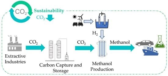
The concept of Carbon Capture Utilisation and Storage (CCUS) has received significant attention in recent years, as the means to further decarbonize the extractive industries. CCUS comprised methods and technologies to collect CO2 from the flue-gas and from the atmosphere and provide safe and permanent storage options, i.e., Carbon Capture and Storage (CCS), followed by recycling the CO2 for the production of valuable products, such as methanol (MeOH), i.e., Carbon Capture and Utilisation (CCU) [4].
CCS technologies can be classified into three different categories, depending on the suitability of each approach to industrial processes. These categories include pre-combustion, post-combustion and oxy-combustion technologies. Pre-combustion capture refers to the removal of CO2 from fossil fuels before the combustion’s completion [6]. In these applications, a feedstock, such as coal, is partially oxidized in steam and oxygen/air at high temperature and pressure by a gasification process to produce synthesis gas, also known as syngas. The syngas, containing mostly carbon monoxide (CO), CO2 and hydrogen (H2), typically undergoes the water gas shift (WGS) reaction, for the conversion of unexploitable CO to CO2, which can be captured and later stored or transported. Post-combustion capture refers to the capturing of CO2 contained in flue-gas streams. These technologies typically operate at low pressures, and are most suitable for the processing of gases with low CO2 concentrations, 5–15%. Post-combustion capture is an already mature technology, finding application in various fields such as oil refineries, petrochemical plants and other industries [7]. Of all the available techniques, absorption-based capture is widely researched and utilised, with proven high efficiencies from laboratory to commercial scale. Specifically, amine-based CO2 capture is the most commonly used approach, reaching capture efficiencies up to 95% and CO2 purities higher than 99%. Oxy-combustion capture refers to the capturing of CO2 deriving from the combustion of fuels with pure or nearly pure oxygen instead of air. In oxy-combustion, nitrogen is separated from the air, resulting in almost zero nitrogen oxides (NOx) formation. As a result, the flue-gases of the combustion have CO2 content as much as 90% [8]. These high contents enable larger amounts of CO2 to be captured and utilised in carbon transformation units.
In 2021, 27 CCS units were already operating globally, with 4 more being under construction [9]. On the global scale, these facilities account for a 36.6 Mtpa CO2 captured and stored. The field of activity and capture capacities of these units are summarized in Table 1. Concerning extractive industries, the Ultra-Low CO2 Steelmaking (ULCOS) research project proposed various novel CCS routes aiming for the reduction of CO2 emissions by 50% in the steelmaking industry [10]. It was estimated that, while process modifications, such as the utilisation of top gas recycle blast furnaces (TGR-BF) for replacing hot blast with pure oxygen, allow for 20–25% reduction, only CCS technologies are capable of 55–60% overall reduction.
CCU technologies refer to the utilisation of CO2 for the production of valuable products including urea, MeOH, formaldehyde, formic acid, carbamates, polymer-building blocks and fine chemicals. CCU can be divided into five main utilisation pathways including CO2 through chemical conversion, mineral carbonation, enhanced oil recovery, biological conversion and direct utilisation [11]. Among them, the leading category in the sector is chemical conversion which refers to the conversion of carbon into urea, formic acid, organic carbonates, and fine chemicals such as biotin, etc. In addition, CO2 can be converted to fuels such as methane, MeOH, and syngas through CO2 hydrogenation and the Fischer–Tropsch reaction. The CO2 to fuels and chemicals pathway offers several advantages for the extractive industry, contributing to the decarbonisation goals as well as the additional sustainable production of fuels and chemicals, and the reduction of fossil-fuel consumption.
Among CO2 by-products, urea and MeOH are the leading consumers of CO2 in industry with an annual consumption of CO2 of more than 110 Mt/year [12]. Respectively, in 2021, global MeOH demand reached more than 164 million tonnes, seeing constant rise [13]. MeOH sees use in multiple sectors, from fuel for the automotive and marine sectors, to feedstock for plastics manufacturing, to pharmaceutical applications. For the automotive and marine sector specifically, production of MeOH-based fuels accounted for 31% of the global MeOH consumption, with 11.7 million tonnes being used for gasoline blending and combustion in 2021 [14,15]. The growing popularity of renewable MeOH as a fuel is due to its many environmental benefits, accounting for reductions of up to 95% CO2, 80% NOx and almost 100% in sulphur oxides and particulate matter [16].
This study focuses on CCUS technologies oriented to the production of MeOH on industrial scale. The benefits for extractive industries comprise the significant reduction of the GHG emissions that end up in the atmosphere and increased economic viability, not only by reducing emissions related costs (i.e., carbon taxation), but also creating revenues from the production of valuable products. The study is divided in two sections analysing the CCS technologies and the CCU.
2. Carbon Capture and Storage Technologies for Extractive Industries
The suitability of the CCS technologies for the different industrial applications is highly associated with the related composition of the flue-gases. Considering that typical flue-gases produced by extractive industry activities have low CO2 content, amine-based absorption is considered the most suitable for CO2 capture. Despite this, the flue-gases of extractive industries typically have high concentrations of CO, which cannot be captured and is more toxic than CO2. For this reason, many applications utilise the WGS-enhanced CCS technologies, where CO is transformed to CO2 by the WGS reaction, to increase the overall carbon capture efficiency of the CCS. In this line, the CCS technologies presented in this section are the amine-based absorption for post-combustion capture and storage and the WGS-enhanced CCS, focusing on relative applications in the extractive industry.
2.1. Amine-Based Absorption for Post-Combustion Capture and Storage
Amine-based absorption for post-combustion capture and storage is one of the most commonly utilised technologies for CO2 capture from flue-gases of energy intensive industries, such as extractive industries. These technologies typically comprise of the following main parts: (1) a cooling system for lowering the temperature of flue-gases, (2) an absorption column, where CO2 is captured by the use of amines, (3) a regeneration column, for the removal of CO2 from the amine stream and (4) a multistage compression system, raising the pressure of CO2 to be stored or transported [1]. A conventional amine-based CCS system is shown in Figure 1.
Flue-gases are introduced to the cooling system where the temperature is decreased to the absorption column operating conditions. The cooled gases are then fed to the absorption column’s bottom where, moving upwards, make contact with a liquid amine stream moving downwards from the column’s top. CO2 absorption by the amine takes place on the column’s trays, designed to increase the contact area.
Liquid amine containing the absorbed CO2 (rich amine) is then compressed, preheated and fed to the regeneration column, where separation of CO2 from the amine occurs. The amine stream enters the regeneration column and concentrates at its bottom. The bottom is continuously heated for the volatile CO2 to be vaporized and exit the column from the top. After initial separation, the liquid amine in the column’s bottom is fed to a reboiler, for further CO2 vaporization and separation. The low CO2 containing amine stream (lean amine) is then cooled and fed to the top of the absorption column, closing the amine loop.
The CO2 stream exiting from the regeneration column’s top is condensed and fed to a flash separator where impurities such as amine and water are removed and sent back to the column. The purified CO2 stream then passes through a multistage compression system and is afterwards condensed and repressurized to be stored in tanks.
2.2. Amine-Based Absorbents
2.2.1. Primary Amines
Monoethanolamine (MEA) is one of the most widely used primary amines in amine-based CCS technologies, achieving removal capacities from 87.1 to 100% and producing CO2 of more than 99% purity [17]. Other primary amines used are 2-(2-aminoethoxy) ethanol (DGA), 1-amino-2-propanol (1A2P) and 2-amino-1-butanol (2A1B). Primary amines are very commonly used due to their fast kinetics, high water solubility, as well as their low price. They are typically used in aqueous form rather than in their pure state.
CO2 capture by amines is a four-step reaction process, including the ionization of water, the CO2 hydrolysis and ionization, the protonation of alkanolamine and lastly the formation of carbamate [17]. The reactions taking place are shown below:
H2O(aq) → H+(aq) + OH−(aq)
CO2(g) + H2O(aq) → HCO3−(aq) + H+(aq)
RNH2(aq) + H+(aq) → RNH3+(aq)
RNH2(aq) + CO2(aq) → RNHCOO−(aq) + H+(aq)
Due to its commercial popularity, MEA has drawn the most attention. In 2021, Akram et al. used a typical 30 wt%. MEA system as a benchmark for comparing with a 40 wt% MEA [18]. The study considered a 6.6 vol% CO2 gas stream. It was demonstrated that the second system was able to achieve CO2 capture efficiency of 89.6%, practically equal to the 90% of the benchmark, with the main advantage being the 25.1% reduction in regeneration energy consumption. In addition, it was concluded that increasing the regeneration temperature from 125.7 to 126.8 °C increased the capture efficiency and capacity to 91% and 74.6 g CO2/kg MEA, respectively. On the other hand, increase in the regeneration temperature accounted for a 12.3% increase in overall energy consumption, as well as faster thermal degradation of the solvent.
An amine-based CCS system using the conventional 30 wt% MEA was also studied in the pilot plant of Niederaussem, from 2017 to 2019 [19]. The flue-gas of the plant had a CO2 content of 14.2%. The system achieved carbon capture efficiency of 90%, with a capacity of 0.25 tonnes CO2 daily. The focus of the particular study was the degradation of MEA, defined by the formation of oxidative degradation products, such as acetate, formate and oxalate, as well as the increase in trace elements, such as chloride, sulphur, sulphate, nitrate and iron. The results showed a 0.47 wt% degradation after 100 h, accounting for MEA consumption of 0.21–0.35 kg/t CO2.
Pellegrini et al. investigated the absorption capacity of DGA as an alternative to the conventional MEA [20]. In this study, the efficiency of a 13–27 wt%. MEA system was compared to an 8–27 wt% DGA., on a flue-gas of 7 wt% CO2. The results showed that the MEA system achieved 95% capture efficiency in comparison with the 88% of the DGA system, both operating at 20 °C. Despite this, it was concluded that the temperature in which the DGA system achieved efficiency of 90% was lower than what the MEA system required to achieve the same results, 63 °C compared to 67.5 °C. In addition, the reported regeneration efficiency of DGA was higher. For a reboiler operating at 110 °C, DGA regeneration efficiency was 90%, in comparison with the 66% of MEA. The studies conducted for MEA and DGA systems prove there are advantages to both approaches, depending on the application. The carbon efficiencies of various primary amine solvents in CCS systems are summarized in Table 2.
2.2.2. Non-Primary Amines
In addition to primary amines, various secondary and tertiary amines also see use in numerous applications across the industry. Typical secondary amines for CCS systems include 2-(methylamino) ethanol (MMEA), N-ethylmonoethanolamine (EMEA) and the most commonly used diethanolamine (DEA) [6,7,21,22]. These amines display similar behaviour with primary amines, presenting high capture efficiencies of up to 90% as well as high regeneration energy demand, due to carbamate formation. Typical regeneration temperature for such amines is 70–200 °C [6,23]. The reaction mechanisms are also similar and can be expressed simply by substituting primary amines (RNH2) with secondary amines (R2NH) [24].
Barzagli et al. compared the performance of MMEA and EMEA and other amines, such as MEA, for a gas mixture of 15% CO2 [25]. All experiments used 0.12 mol of amine. MMEA achieved capture efficiency of 92%, at 21 °C and 1.0145 bar. EMEA achieved 92.4%, at 24 °C and 1.0013 bar. In comparison, the 30% MEA solvent achieved 82.2% capture efficiency despite operating at slightly higher temperature and pressure than EMEA, 25 °C and 1.0067 bar.
Wang et al. conducted a study in 2021 over a lab-scale CO2 capture system including DEA [26]. The study proposed an integrated absorption and mineralization process where, after the absorption, CO2-rich solvents are regenerated by mineralization with semidry desulphurization slag. The experiment utilised a 15 vol% CO2 and 85 vol% N2 gas. After absorption, the CO2-rich solvent was mixed with Ca-rich compound for the formation of calcium carbonate and the regeneration of the solvent. The results showed CO2 loading of 0.73 and 0.18 mol CO2/mol DEA for the rich and lean DEA, respectively. The desorption process achieved efficiency up to 85%. The main advantage of this approach was the lack of need for a compressor and reboiler in the regeneration system, thus reducing the energy consumption by as much as 93.7% in relation to conventional systems.
Tertiary amines for CCS systems include 2-(dimethylamino) ethanol (DMAE), N-methyldiethanolamine (MDEA) and 2-diethylaminoethanol (DEAE). In recent years, such amines have drawn much attention due to their high CO2 absorption capabilities of 1 mol CO2/mol solvent, almost two times higher than primary and secondary amines [26]. In addition, the inability of these amines to react with CO2 accounts for no carbamate’s formation [24]. Instead, bicarbonate ions are formatted, which require far less regeneration energy, approximately 58.5 kJ/mol compared to 86.9 and 68.9 kJ/mol for primary and secondary amines, respectively [6,23,27].
The main disadvantage of tertiary amines is the low CO2 absorption rate of approximately 2.13 mol CO2/hr [26]. To counter this issue, these amines are usually mixed with promoters such as piperazine (PZ) or carbonic anhydrase (CA) to increase absorption [22,28]. The reaction taking place is the following [23]:
R3N(aq) + CO2(g) + H2O(aq) ↔ R3NH+(aq) + HCO3-(aq)
Antonini et al. examine the use of an MDEA carbon capture system for producing low-carbon H2 [29]. The system utilised a high-pressure and a low-pressure flash separator for the recycling of CO2 not absorbed and semi-lean amine solvent that can further contribute to absorption in the absorption column. The gas considered in this study contained 16.27 mol% CO2. The solvent was a conventional 40 wt% MDEA. The results of the study showed that utilising these recycling streams in the system accounted for a 54.5% reduction in regeneration energy demand, and capture efficiency of 90%.
Zhao et al. also examined post-combustion CCS using an MDEA+PZ solvent for a 650 MW power plant [30]. The flue-gases treated had a CO2 content of 12%. The study examined the effect of the MDEA/PZ ratio as well as the targeted carbon capture capacity on the overall performance of the system and energy demand. The results showed that 30% and 20% of MDEA and PZ, respectively, allowed for high carbon capture efficiencies of 90%, without significantly increasing the reboiler heat duty for the amine regeneration.
Another study of a MDEA CCS system was conducted by Jaffary et al. in 2021 [31]. In this study, polyamines were used as activators for the absorption of 100% CO2 gas. The polyamines examined were polyethylenimine (PEI-B), tetraethylenepentamine (TEPA) and PZ. The results of the study showed that MDEA enhanced with PEI-B had an increased CO2 loading and specific desorption rate of 1.08 mol CO2/mol solvent and 0.0385 mol CO2/mol amine/min, respectively. Despite these benefits, incorporating PEI-B in the solvent accounted for increased viscosity, which results in decreased CO2 absorption rates. PZ on the other hand accounted for a moderate increase in both the CO2 loading and desorption rate, 0.67 mol CO2/solvent and 0.0352 mol CO2/mol amine/min, respectively, without increasing viscosity. The performance of various secondary and tertiary amine solvents is summarized in Table 3.
CCS systems in extractive industries aim for the exploitation of CO2 after the separation from the amine solvents, therefore, the most efficient amines are those having high capture efficiencies but also low regeneration energy, to allow for higher separation and reduced energy consumption.
Primary amines offer high capture efficiencies, up to 95% for the commercial MEA. Other primary amines, such as DGA, require significantly less regeneration energy while also having high capture efficiencies and thus can be considered another viable option. Secondary amines exhibit similar capture efficiencies to primary amines. Studies comparing MEA with EMEA specifically, have shown that EMEA can achieve carbon efficiency as high as 92.4% in comparison to MEA’s 82.2%, with a slight increase in temperature and pressure. Tertiary amines, however, specifically MDEA, provide similarly high carbon capture efficiencies, while also requiring significantly less regeneration energy, 1.34 MJ/kg CO2, than other amines [32]. For these reasons, MDEA is considered one of the most efficient options, used in various applications in CCS systems in the industry. While these amines have lower absorption rates on their own, these disadvantages are easily dealt with when mixed with promoters, especially PZ. In that sense, the use of MDEA+PZ solvents in novel systems utilizing recycle streams can be considered one of the most optimal approaches for CCS systems.
2.3. Innovative Amino Acids
Amino acids have seen significant research over the years as an energy-efficient replacement of conventional amines. The use of these solvents allows for the mitigation of CO2 emissions in plants while also reducing the economic impact of these technologies.
In 2019, Moioli et al. examined a CCS system capturing CO2 by precipitating potassium taurate solvent [33]. The unit’s layout is nearly identical to the conventional amine-based, with the main differences lying in the optional components related to the processing of formed solids. Specifically, the reactions taking place result in the formation of solid taurine. Precipitation of taurine shifts the equilibrium toward the formation of more products, resulting in increased CO2 capture. The production of solid taurine results in a slurry, comprising of solid taurine and a mixture of ionic species and water, obtained at the absorption’s column bottom, which can optionally be fed to a solid-liquid separator, where supernatant liquid is returned to the absorption column, while the solids are led to the regeneration column, after being dissolved.
The advantage of this approach lies in the lower regeneration energy required. Specifically, the amino acid rich slurry stream entering the regeneration column has a lower pH which favours the desorption of CO2. The case studies examined both the inclusion and not inclusion of a solid-liquid separator in the CCS unit for a 500 MW output power plant. The CO2 removal efficiency was fixed at 90%. The analysis highlighted the benefits of incorporating the optional solid-liquid separator to allow for a fraction of liquid to be recycled to the absorption column without the need of regeneration, thus reducing energy requirements. For a recycle split fraction (liquid recycled/total liquid fed to the separator) of 0.2, corresponding to 0.255 lean loading, the reboiler duty was at its minimum, lower than 2.9 MJ/kg CO2. For comparison, conventional amines such as MEA, have shown reboiler duties as high as 3.8 MJ/kg CO2 for 0.23 lean loading.
Garrabrant et al. also examined the use of amino acid salts for energy-efficient CCS systems [34]. Specifically, the study examined CO2 absorption by a hybrid potassium glycinate and sarcosinate followed by the amino acid regeneration and bicarbonate removal crystallization with a simple bis-iminoguanidine base (GBIG), and examined the regeneration energy with that of industrial benchmarks such as 30% aqueous MEA and 30% aqueous sodium glycinate (SG). The results showed that, while the required regeneration energy for SG was higher than MEA, approximately 5.7 MJ/kg CO2 in comparison to 4.5 MJ/kg CO2, the required regeneration energy for the potassium glycinate/sarcosinate + GBIG case was 3.4 kJ/kg CO2, a reduction of 24% in comparison with MEA. This reduction in the regeneration energy lies in the ability of the GBIG process to regenerate the solvent in ambient temperatures.
In 2021, Xu et al. also examined the use of amino acid salts for CO2 capture from a flue-gas containing 15% CO2, proposing the encapsulation of amino acid salts into solid particle matrices for the production of liquid amino acid salts hydrogel (LAHP) [35]. The proposed approach allowed for bigger contact areas and more intense interactions with CO2 uptakes increased as much as 40%, compared to stirred aqueous amino acid salts solutions. The study concluded that the heat of absorption for potassium sarcosinate LAHP was 35% lower than MEA’s, 53.3 kJ/mol CO2 in comparison to 81,77 kJ/mol CO2., suggesting lower regeneration energy requirements. In addition, the study proposed the replacement of water with solvents of higher boiling points, i.e., ethylene glycol, to further reduce the required energy. With a boiling point of 60 °C, ethylene glycol opens up the approach of using waste industrial steam to further reduce operational costs. The regeneration energy for the different solvents is shown in Table 4.
2.4. WGS-Enhanced Carbon Capture and Storage
Many industries, including extractive industries, produce flue-gases of very small CO2 concentrations and high concentrations of CO, which is far more toxic and cannot be captured. To tackle this issue, many CCS technologies utilise the WGS-enhanced CCS, which is the incorporation of a CO to CO2 transformation system before capture, in the form of a WGS reactor. Water reacts with CO for the production of CO2 and H2. The produced H2 is separated and can be used in the carbon transformation technologies. The reaction taking place is the following [36]:
CO(g) + H2O(g) ↔ CO2(g) + H2(g), ΔH = −41 kJ/mol
CO conversion to CO2 is highly exothermic and thus is favoured in low temperatures. Specifically, studies have shown than a reduction of the reaction temperature from 800 to 200 °C can increase the equilibrium constant up to 80 times [37]. In addition, the reaction’s equilibrium is proven to be unaffected by pressure increase, but CO conversion is favoured due to higher reaction rates.
WGS reaction commercially takes place in two adiabatic catalytic reactors arranged in series for maximum CO transformation [38]. The first reactor is a high-temperature WGS (HT-WGS) operating with a Fe-based catalyst at 350–500 °C and 10–60 bar, while the second reactor is a low-temperature WGS (LT-WGS) operating with a Cu-based catalyst at approximately 200 °C and 10–40 bar [39]. HT-WGS are characterized by fast kinetics, but equilibrium-limited conversion. On the other hand, LT-WGS have slower kinetics, but are much less limited by the thermodynamic equilibrium, allowing for higher CO conversion. The combination of the two allows for fewer thermodynamic limitations and the ability to adjust the H2:CO ratio in the final gas product.
Despite this, most CCS units using WGS reactors for enhanced decarbonization incorporate a single HT-WGS reactor. The Fe-based catalysts used in such reactors can tolerate small quantities of particles commonly found in the flue-gases of extractive industry’s processes, such as sulphur-based compounds, in contrast with Cu-based catalysts used in LT-WGS reactors [40]. In addition, any traces of hydrogen sulphides (H2S) in the flue-gas can be separated along with CO2 in the absorption process. For these reasons, WGS-enhanced CCS is considered one of the most efficient approaches for CCS in extractive industries. A conventional WGS-enhanced CCS system is shown in Figure 2.
Catalytic Membrane Reactors for WGS Reaction
Commonly used reactors for WGS reaction are catalytic membrane reactors (CMR). Such technologies allow for the immediate separation of either CO2 or H2 from the product stream. This continuous separation allows for higher CO conversion than a conventional reactor limited by equilibrium. Numerous studies have been conducted for high-grade H2 recovery using dense Pd-based, composite Pd-based or silica and zeolite membranes. A conventional CMR for WGS reaction is shown in Figure 3.
For Pd-based CMR, several studies indicate CO conversion up to 98% and H2 recovery up to 94%, but for small-scale reactors [41]. In large-scale applications, multi-tubular systems with membranes of 50–60 μm thickness or composite planar membranes based on foils of 20–25 μm are the most commonly used. Of the two approaches, composite Pd membranes generally achieve higher H2 production rates, due to higher permeances of the thinner membrane.
Catalano et al. investigated the performance of <10 μm Pd membranes over a porous (316 L) stainless steel (PSS) tubular support [41]. The tube-and-shell reactor used was filled with a commercial Fe/Cr catalyst for high temperature WGS reaction. The gas used was decided to simulate actual gasifier syngas, with a composition of 40% H2, 42.2% CO and 17.8% CO2. The H2O:CO ratio ranged from 2.5 to 3.5 and the total feed flow was up to 1.5 Nm3h−1. The temperature raged from 420–440 °C and the pressure was up to 20 bar. The study concluded that for an 8.3 μm Pd membrane and operating temperature and pressure of 440 °C and 20 bar, respectively, CO conversion reached 84.9%, H2 recovery 42.8% and H2 purity 99.5%.
Augustine et al. also investigated the performance of a CMR using Pd-membranes, over different H2O:CO ratios, temperatures, gas compositions, and gas hourly space velocity (GHSV), at a fixed 14.4 bar pressure [42]. The reactor was using an iron-chrome oxide catalyst. The experiments conducted examined both the use of a CO feed as well as a syngas feed with a composition of 22.7% CO, 45.4% H2O, 22.0% H2 and 9.9% CO2, a H2O:CO ratio of 2. For the syngas, results showed that a H2O:CO ratio of 1.3:1 was the optimal, reaching CO conversion and H2 recovery of more than 95% and 85%, respectively, at 450 °C. Increase of the ratio beyond this point had a minor effect on CO conversion, but a negative effect on H2 recovery. Indicatively, at a H2O:CO ratio of 2.5:1, CO conversion and H2 recovery were 94% and 78%, respectively.
Nishida et al. investigated the performance of a silica membrane developed with the counter-diffusion chemical vapor deposition (CVD) method [43]. The silica membrane had a H2 permeance of 1.29 × 10⁻⁶ mol m−2s−1Pa−1. The reactor tube was filled with 1.05 g of a commercial Cu/ZnO/Al2O3 catalyst. The test was conducted with a blast furnace gas (BFG) feed with a composition of 52% N2, 22% CO, 22% CO2 and 4% H2, at 300 °C and 3.05 bar. The study showed that operating the reactor with a space velocity of 7000 h−1 accounted for a CO conversion of 95–97%, H2 recovery of approximately 60% and an H2 purity around 94%. The study also examined the effect of space velocity in the reaction, in the range of 3500 to 10,500 h−1 and concluded that the increase in space velocity resulted in decreased CO conversion and H2 recovery but increased H2 purity.
Battersby et al. also examined the effect of H2O:CO molar ratio in a silica membrane reactor using Cu/ZnO/A2O3 catalyst, prepared by NaCO3 co-precipitation of precursor salts and followed by consequent aging, filtration, washing drying and calcination [44]. The tests were conducted with a fixed reactants’ flow rate of 80 mL/min and varying H2O:CO ratios. It was concluded, that increasing the H2O:CO molar ratio from 1 to 4 increased the CO conversion from 20% to 29%, at 250 °C. The study also examined the effect of temperature on CO conversion for a H2O:CO molar ratio of 1. The results showed that increasing the temperature resulted in increased CO conversion, reaching almost 80% at 300 °C. The performances of the various CMR reactors are summarized in Table 5.
The studies conducted over the CMR reactors using Pd-based membranes show the highest CO conversion and H2 recovery at a temperature of approximately 450 °C. In terms of the H2O:CO ratio, near stoichiometric conditions are generally preferred, as higher ratios negatively affect both the CO conversion and H2 recovery. Considering the operating pressure, the reaction is generally unaffected.
On the other hand, CMR reactors using silica membranes exhibit high CO conversion at relatively moderate temperatures of 300 °C, as well as significantly lower operating pressures. For these reasons, CMR reactors with silica-based membranes can be considered one of the most efficient options. Incorporating such reactors before amine-based CCS allows for increased CO2 content in the stream and thus maximum carbon capture.
2.5. CCS Applications in Extractive Industries
The transformation of an energy-intensive industrial sector towards the transition to a low carbon economy, without reducing the production volume, requires joint, collaborative efforts to develop and invest in novel process designs and solutions. In this context, CCS applications in extractive industries are highlighted with main focus on the capture, transport and storage of CO2 that would otherwise have been emitted to the atmosphere.
The ULCOS project investigated various CCS technologies for implementation in extractive industries. These technologies were pressure swing adsorption (PSA), vacuum pressure swing adsorption (VPSA), VPSA and cryogenic separation and compression, amine-based capture and compression and PSA and cryogenic distillation and compression [10]. The process gas composition was almost identical for all technologies, with compositions of 2.7–3 vol% CO2, 67.8–71.4 vol% CO, 12.1–13 vol% H2, 13.5–15.7 vol% N2 and 0–2.1 vol% H2O. The results showed that of all the aforementioned technologies, amine-based capture and compression and PSA and Cryogenic distillation are the most efficient approaches accounting for almost 100% CO yield in the recycled gas and 100% captured CO2 purity. For comparison, PSA accounted for 88% CO yield and 79.7% captured CO2 purity. In addition, these technologies were concluded to be the only two 100% suitable for CO2 transport and storage.
WGS-enhanced CCS has received significant attention for utilisation in extractive industries over the last years. European project C4U, started in 2020, examined the utilisation of a WGS-enhanced CCS system in iron and steel industries [5]. The performance of the system was compared with a base case scenario of a conventional amine-based CCS without a WGS reactor. The flue-gas examined was a BFG with a composition of 21.2 moldry% CO2, 22.7 moldry% CO, 0.2 moldry% C2H4, 2.4 moldry% H2, 53.5 moldry% N2 and a total flow rate of 125 kg/s. The amine-based CCS systems utilised a 25 wt% MDEA solvent. In the base case, the CCS system delivered 36.8 kg/s of 98.2% pure CO2. The system also accounted for approximately 0.92 kmol/s of CO and 0.03 kmol/s of uncaptured CO2. The WGS-enhanced CCS system delivered 66.3 kg/s of 98.1% pure CO2, an increase of approximately 80%. The system also accounted for approximately 0.01 kmol/s CO and 0.0036 kmol/s uncaptured CO2, a decrease of almost 99% and 88%, respectively. The results of this examination clearly displayed the advantages of the WGS-enhanced CCS technologies over the conventional amine-based.
The STEPWISE project executed within the European H2020 LCE program also aimed for the demonstration of an advanced pre-combustion CO2 removal technology for iron and steel industries [45]. The technology was based on sorption enhanced water gas shift (SEWGS) using regenerative solid adsorbents at elevated temperatures. The solid adsorbent was regenerated by pressure swing, resulting in CO2-rich streams suitable for storage and transport. The H2 produced by the WGS reaction was considered suitable for power generation. In the project, the process was demonstrated at a scale of 14 t/day CO2 removal. For simple integration of the technology, carbon intensity was reduced to 1.26 t CO2/t steel, with an energy consumption of 1.95 MJ/kgCO2 and CO2 avoidance costs of 32 ᯘ€/t CO2. For intensified implementation, focusing on internal uses and electricity production, carbon intensity was reduced to 0.60 t CO2/t steel.
The technology developed utilised a WGS active sorbent, allowing for the in-situ removal of CO2, to account for limitations set by equilibrium. Thus, there is no need of two or more WGS reactors [46]. The dry gas considered had a conventional composition of 19% CO, 25% CO2, 3% H2, 15–20 ppm H2S + carbonyl sulphide (COS) and 53% N2. Implementation of the WGS reactor allowed for the reduction of CO content to 5%. The SEWGS unit utilised a catalytically active potassium-promoted hydrotalcite-based sorbent for both CO conversion completion and separation of CO2 from H2.
In 2020, Manzolini et al. performed a techno-economic assessment of SEWGS technology for integration in a steel-plant, as a follow-up study of the STEPWISE project [47]. The study compared the performance of a conventional amine wet scrubbing technology and the solid adsorption technology of the STEPWISE project. Simulation results showed that the SEWGS using solid absorbents accounted for a specific energy consumption for CO2 avoided (SPECCA) of around 2.5 MJ/kg CO2, in comparison to the 4.8 MJ/kg CO2 of the conventional amine scrubbing.
3. Carbon Capture and Utilisation Technologies for Extractive Industries
CCU solutions typically opt for the transformation of CO2 to valuable products, such as MeOH, using an external H2 feed. Commonly used approaches comprise the CO2 hydrogenation, for the immediate utilisation of the captured CO2, and the enhanced CO2 transformation by the Fischer-Tropsch reaction, where CO2 is transformed into CO by the reverse water gas shift (RWGS) reaction to allow for higher carbon conversions and MeOH production. In this frame, CO2 hydrogenation and the Fischer–Tropsch reaction process will be reviewed, as the one of the most commonly used and promising approaches for MeOH production in extractive industries.
3.1. CO2 Hydrogenation
CO2 hydrogenation utilises reactors where CO2 reacts with H2 for the production of methane or MeOH. A typical CO2 hydrogenation system is comprised of the following main components: (1) a CO2 hydrogenation reactor and (2) a distillation column for the separation and collection of produced MeOH. A conventional system using CO2 hydrogenation for MeOH production is shown in Figure 4.
CO2 feed is mixed with an H2 stream and preheated before entering the reactor. Inside the reactor, the CO2 hydrogenation occurs, and MeOH is produced, as well as by-product water and CO. CO specifically results from the RWGS reaction, naturally occurring in the reactor. CO produced reacts with the H2 in the Fischer-Tropsch reaction for enhanced production of MeOH. The reactions taking place in the reactor are the following [48]:
CO2 + 3H2 ↔ CH3OH + H2O, ΔH298Κ = −49.16 kJ/mol
(CO2 hydrogenation)
(CO2 hydrogenation)
CO2 + H2 ↔ CO + H2O, ΔH298K = +41.21 kJ/mol
(RWGS)
(RWGS)
CO + 2H2 ↔ CH3OH, ΔH298K = −90.77 kJ/mol
(Fischer-Tropsch)
(Fischer-Tropsch)
The stream exiting the reactor consists of MeOH, water and unreacted CO2, CO and H2, and therefore, requires separation. The stream is condensed and passes through a flash separator where the unreacted gas is separated from liquid MeOH and water. A significant part of this unreacted gas is repressurized and recycled back to the reactor to enhance the final CO2 conversion.
The liquid MeOH and water are separated in the distillation column of the system. The stream introduced at the middle trays concentrates at the bottom of the column, which is constantly heated for the vaporization of volatile MeOH and separation from water. After initial vaporization, the liquid in the bottom of the column is fed to a reboiler which facilitates further separation. The gaseous MeOH exits the distillation column from the top, and the stream is condensed and passes through a flash separator for the separation of any water vaporized along, and the production of the final MeOH product.
3.1.1. CO2 Hydrogenation Reactors
The main concern when developing a CO2 hydrogenation reactor is the efficient removal of the heat produced by the highly exothermic reaction. Efficient heat removal facilitates avoiding the formation of by-products, achieving high CO2 conversion by low outlet temperatures and good energy efficiency by internal heat recovery [49]. Current designs have shifted from the previously used quench reactors to the quasi-isothermal steam-raising fixed bed reactors, or steam-raising converters (SRC), which allow for more efficient heat recovery and temperature control [49].
One of the most commonly used SRC reactors is the multi-tubular packed bed catalytic reactor, also known as the Lurgi reactor. Lurgi reactor comprises multiple tubes filled with catalyst particles to enhance the reaction rate and overall CO2 conversion. Such designs incorporate an inner cooling system, in the form of a coolant, typically water, flowing between the space of the tubes. The feed gas feed flows through the tubes in an axial direction. Approximately 80% of the reaction heat is converted to medium pressure steam [50]. A conventional Lurgi reactor for CO2 hydrogenation is shown in Figure 5.
3.1.2. CO2 Hydrogenation Catalysts
Currently, the majority of commercial low-pressure catalysts are CuO and ZnO based. In most cases, Al2O3 carriers are utilised, along with various stabilizing additives and promoters such as Zr, Cr, Mg and rare earth metals [49]. Several studies showed space time yields (STY) for CO gases being 0.7–2.3 kg of MeOH per litre of catalyst. For CO2 gases the STY was significantly lower, 0.4–0.8 kglcat−1h−1. The studies considered operational pressures 40–100 bar and GHSV about 10 000 h−1 [45,50,51]. Modern copper catalysts achieve selectivity of more than 99% for conventional gases [52]. Impurities in the gas feed, high pressure and temperature, high CO:H2 and CO:CO2 ratios and low space velocities are some of the factors reducing MeOH selectivity.
The typical lifetime of industrial catalysts is 4–6 years [49]. Deactivation as a result of poisoning or thermal sintering is the main limitation of the catalysts’ lifetime. For copper-based catalysts, sulphur compounds and chlorides are the major causes of poisoning, resulting in blocking of active sites and acceleration of sintering, respectively. Arsenic and carbonyls are other poisons reported, promoting the Fischer-Tropsch reaction and thus decreasing selectivity [53]. To prevent such issues, a prior gas cleaning step is usually implemented, as well as guard beds, such as ZnO targeting sulphur, for the catalyst’s protection [52]. For commercial Cu/ZnO catalysts, typical gas requirements are: 0.05–0.5 ppm H2S, 1 ppb HCI, few ppb metal carbonyl, less than 0.1 mg N m−3 particles, less than 1 mg N m−3 tar and less than 0.25 mg N m−3 alkalis [49].
Liao et al. examined the effect of the H2:CO2 ratio and temperature of the reaction over a Cu/rod ZnO/Al2O3 and Cu/plate ZnO/Al2O3 catalyst at 45 bar [54]. Results showed that increasing the H2:CO2 ratio from 2.2:1 to 2.5:1 had a positive effect on the CO2 conversion, but decreased MeOH selectivity for both catalysts at 270 °C, as well as 280 °C. Increase in temperature also resulted in increased CO2 conversion but decreased MeOH selectivity for both catalysts and the different H2:CO2 ratios. The results also suggested that the Cu/rod ZnO/Al2O3 catalysts exhibited slightly higher CO2 conversion but significantly lower MeOH selectivity.
Sahki et al. examined the effect of pressure in the reaction over a CuO/ZnO/Al2O3 catalyst [55]. The reaction took place at 230 °C at varying pressures of 1–75 bar, with a flow rate of 2 L h−1 and a stoichiometric H2:CO2 ration of 3:1. The results showed that increasing pressure from 1 to 75 bar increased the CO2 conversion from 3.1 to 11.9%, and MeOH selectivity from 5.3 to 47.1%. CO selectivity decreased from 94.66 to 52.9%.
To highlight the effect of the H2:CO2 ratio and pressure in the reaction, Bansode et al. examined the performance of a Cu/ZnO/Al2O3 catalyst for a 10:1 ratio and a high pressure of 360 bar [56]. The results showed a CO2 conversion of 65.8% on a single pass, almost six times higher than other applications opting for near stoichiometric ratios and moderate pressures. The MeOH selectivity was 77.3%.
Table 6 summarizes the performance of the various Cu-based catalysts for CO2 hydrogenation found in literature.
The studies on the performance of these catalysts show the importance of the operational parameters in the CO2 hydrogenation reaction. In terms of H2 supply, high H2:CO2 ratios tend to benefit the overall CO2 conversion. Despite this, raising the H2:CO2 ratios results in decreased MeOH selectivity, as well as increased energy demand and cost for the production of H2. For these reasons, the majority of applications opt for a stoichiometric H2:CO2 ratio of 3:1.
Operational temperature also significantly affects the reaction. Higher temperatures result in increased overall CO2 conversion but decreased MeOH selectivity. The most influential parameter is pressure. While an increase in pressure results in significantly higher conversion, applications need to account for the safety of the systems. Thus, reactors typically operate at pressures up to 100 bar.
3.2. Enhanced CO2 Transformation by Fischer-Tropsch Reaction
CCU commonly utilise RWGS reactors for the conversion of CO to CO2 to increase carbon conversion efficiency. This approach aims for optimising the CO2 hydrogenation reaction with the Fischer-Tropsch reaction. As the Fischer-Tropsch reaction for MeOH production is almost twice as much exothermic, ΔH298K = −90.77 kJ/mol compared to ΔH298Κ = −49.16 kJ/mol, the required activation energy is lower, resulting in increased reaction rate and conversion to account for the decreased selectivity. A conventional system for MeOH production from CO2 utilising a RWGS reactor is shown in Figure 6.
The RWGS reaction is endothermic, thus high reaction temperatures are required, increasing the energy consumption of such systems. Specifically, CO becomes the main product of the reaction at temperatures above 700 °C [58]. The H2:CO2 ratio for the RWGS reaction ranges from 1:1 to 4:1. In general, the chemical equilibrium of the reaction is pressure independent.
For the RWGS reaction, numerous reactor designs have been studied such as the packed-bed, the fluidized-bed and the moving-bed reactors. A number of catalysts have been investigated for the RWGS reaction, with precious metals such as Pt, Pd, Ru and Au finding successful application as the active sites of the catalysts [59]. Recent studies have also focused on Cu, Ni and Fe catalysts, as the high prices of noble metals such as Pt limit their availability. The results show that, while Pt catalysts exhibit the highest CO2 conversions, Cu and Fe display the highest CO selectivity [60].
Zhuang et al. specifically examined the performance of a 0.5 wt% Ru-promoted Cu/ZnO/Al2O3 catalyst compared to a conventional Cu/ZnO/Al2O3 catalyst, under identical operational parameters. The results showed that under 500 °C, CO2 conversion of the Ru-promoted catalyst was 46%, in comparison to 17%. Metal catalysts are typically coupled with reductive oxides such as CeO2, MN2O3, CrO2, FeOX or TiO2 [61]. In addition, many catalysts incorporate transitional metals or rare earths such as Zr, Fe, La and Y into the reducible oxide lattice [62].
To demonstrate the efficiency of high temperatures in the reaction, various studies examined the performance of catalyst under different reaction temperatures. Zhuang et al. also examined a similar Pt/TiO2 at a slightly higher H2:CO2 ratio, 3:1, and higher temperature, 600 °C. The study showed that when operating under these conditions, CO2 conversion reached 56% [63]. Kim et al. in their study examined the performance of a Pt/Al2O3 and a Pt/TiO2 catalyst under different temperatures, keeping other operational parameters such as H2:CO2 (3:2.1) ratio and space velocity the same [64]. The results showed that, at 500 °C, CO2 conversion was approximately 34% and 39%, while at 300 °C it was only 6% and 15%, for the Pt/Al2O3 and Pt/TiO2 catalyst, respectively.
For even higher temperatures, Zonetti et al. examined the performance of a Ni/Ce0.75Zr0.25O2 catalyst at 700 °C, at a H2:CO2 ratio of 3:1. The study showed that when operating at these conditions, CO2 conversion reached 62.5%. The performance of the various catalysts is summarized in Table 7.
Studies conducted on the effect of CO2:CO ratio in MeOH production have shown that the MeOH yield for CO2-based gases is 18–58% at 200–250 °C and 50–100 bar, significantly lower than for CO-based gases, which accounted for 55–89% [49].
Klier et al. examined the effect of CO2:CO ratio in the production of MeOH over a Cu/ZnO-based catalyst [68]. The results showed that the complete absence of CO2 from the syngas accounted for reduced carbon conversion, as a small amount is required as a promoter of the reaction. Despite this, at higher concentrations, carbon conversion was significantly hindered. At 250 °C, carbon conversion to MeOH for a CO2:H2 gas of zero CO content was only 9.7%. For a syngas of 2:28 CO2:CO ratio, at the same temperature and H2 supply, carbon conversion was up to 69.7%.
Ng et al. also examined the influence of the CO2:CO ratio in the feed composition for the production of MeOH and dimethyl ether (DME) over the commercial CuO/ZnO/Al2O3 catalyst [69]. At 250 °C, 50 bar and a GHSV of 27,500 h−1, the MeOH yield was the highest, more than 50% at less than 10% CO2:(CO2+CO) ratio. In the absence of CO from the gas, MeOH yield was lower than 20%. The effect of the CO2:CO ratio in the production of MeOH for the various catalysts is summarized in Table 8.
Enhanced CO2 transformation by the Fischer-Tropsch reaction is a widely used approach for the production of MeOH. For the transformation of CO to CO2, the commercial Cu/ZnO/Al2O3 catalyst is used, mixed with precious metals such as Ru to enhance the conversion. As the RWGS reaction is highly endothermic, high temperatures of 500 °C are generally preferable. In terms of H2:CO2 ratio, near stoichiometric ratios are generally preferred.
Incorporating a RWGS reactor prior to the CO2 transformation process significantly increases the overall carbon conversion and MeOH production. Studies have shown that the production of MeOH from CO gases can be up to 6–7 times higher than from CO2 gases. Despite this, such systems account for higher energy consumption, thus incorporating them or not depends on the techno-economical specifications and the desired MeOH production capacity of each system.
3.3. Applications of CO2 Transformation to MeOH in Extractive Industries
MeOH production from the flue-gases of extractive industries, such as steel mills, is an already commercial technology. For instance, in 2011, 11% of the total MeOH production of China, which is currently the largest market, derived from such processes [70]. However, most of these processes were not focused on exploiting renewable electricity for the production of the H2 required for the MeOH synthesis, often increasing the total CO2 emissions [71]. To tackle such issues, numerous studies and projects have focused on modernizing the process to achieve the industries’ decarbonization.
Carbon2Chem is one of the projects focusing on the power to MeOH concept, promoting numerous studies on the subject [72]. Bender et al. examined the coupling of steel and chemical production, proposing different scenarios, one of them being the direct reduced iron (DRI) process coupled with MeOH production by green H2, using the flue-gases of a steel mill [73]. The study was conducted for the implementation of the scenario in the Duisburg site, with a nominal production rate of 12 MMTA of iron products. The flue-gases derived by a blast furnace by 85.5%, a coke-oven by 9.45% and a basic oxygen furnace by 5.05%, and comprised mostly of CO, CO2, N2 and H2. The results of the study suggested that the proposed scenario can reduce the total CO2 emissions from 21.9 to 0.5 MMTA, a reduction of almost 98%, and is dimed the most efficient approach for the decarbonization of the site’s activities.
Schlüter et al. developed a model for the catalytic conversion of steel mill gases for MeOH synthesis [70]. Three different cases were examined, with different rates of coke oven gas (COG), BFG and basic oxygen furnace gas (BOFG) in the flue-gas. The study examined the commercial Cu/ZnO/Al2O3 catalyst with a bed porosity of 0.38. The reactor was 7.5 m in length, with tubes of 44 mm diameter. The number of tubes varied for every examined case. The reaction took place at 240 °C and 85 bar. The steel mill had a production capacity of 16.4 ktsteel/day, with a CO2 production of 2.74 kt/day (0.34 ktCO2/day by COG, 1.38 ktCO2/day in BFG and 1.02 ktCO2/day in BOFG). Case 1 examined the MeOH production without additional H2 demand, by limiting the BOFG content in the flue-gas. Case 2 examined the use of additional H2 for maximum utilisation of BOFG. Both these cases excluded BFG, accounting for MeOH productions of 155.81 and 370.32 kt/a, respectively. Case 3 examined the utilisation of the BFG gases, accounting for a MeOH production of 669.05 kt/a. The carbon efficiency of cases 1,2 and 3 were 90.6%, 92.8% and 82.5%, respectively.
The FReSMe project, which concluded in 2021, also aimed for the production of MeOH from CO2 deriving from the residual steel gases recovered from an industrial blast furnace [74]. The produced MeOH was to be used as fuel in ship transportation. The pilot plant was designed for a nominal production rate of 50 kg/hr with an input of 800 m3/hr CO2. The pilot plant constructed utilised a SEWGS CCS system for the production of a CO2 rich stream and a H2/N2 stream from the BFG [75]. The CO2 rich stream was cooled, buffered and compressed before entering the desulphurization step. After desulphurization, the pure CO2 stream was introduced to the reactor system for the production of MeOH to be stored in tanks. The H2/N2 stream passed through a membrane skid for the separation of H2 and N2. The produced H2 was used as a feed for the CO2 hydrogenation reaction, along with the feed produced by an electrolyser. The FReSMe project is the integration of the CCS technology developed in the aforementioned STEPWISE project and the improved technology for MeOH production by CO2 developed in the MefCO2 project [74,76].
MefCO2 project designed a Lurgi reactor utilising a commercial CuO/ZnO/Al2O3 catalyst for CO2 hydrogenation [77]. The experiments showed that at 20 bar, 280 °C and 12,030 h−1 GHSV, CO2 conversion reached 25% in a single pass, with MeOH selectivity being 10%. At 200 °C, keeping the other operational parameters constant, CO2 conversion was less than 5%, while MeOH selectivity reached as high as 80%. The results proved that higher temperatures result in higher conversion while lower temperatures result in higher selectivity, thus moderate temperatures are considered optimal. The project’s pilot plant at Niederaussem was designed for 1 tonne of pure MeOH production daily. The reactor developed was a 7.022 m Lurgi reactor of 2962 tubes of 0.053 m diameter each. The catalyst used was a conventional Cu/ZnO/Al2O3 with a bed porosity of 0.39. The reactor operated at 80 bar, with a feed of 10.2 kg/hr of H2 and 66.1 kg/hr of CO2, a conventional H2:CO2 molar ratio of 3:1 [77]. The system also incorporated a recycling stream, with a CO2 recycle ratio (fresh CO2 feed/CO2 feed of reactor) of 0.25, thus the system accounted for 4.89 kmol/h and 1.63 kmol/h of fresh H2 and CO2, respectively, and a MeOH production of 1.2 ton/day.
4. Sustainability Analysis of MeOH Production from CO2
MeOH production through CO2 is an approach seen constant rise in popularity and application. Various studies over the recent years have focused on the environmental impact and the sustainability of these systems. Key points comprise the comparison of MeOH production from CO2 with the conventional processes, and the energy efficiency of the process.
In 2021, Ryoo et al. conducted a Life Cycle Assessment (LCA) for the CO2 to MeOH conversion process and its energy optimization [78]. The study examined three different scenarios, MeOH production from the CO2 deriving from coal gasification, coal coking and production by photocatalytic conversion. All systems utilised an amine-based CCS system using MEA. For CO2 hydrogenation, a La/Cu/ZrO2 catalyst was examined. The study considered various energy sources for the supply of the required heat and electricity in the system. Solar thermal, natural gas (NG), oil, coke (coal) and steam were examined as heat sources. Nuclear, wind, photovoltaic, hydro and grid electricity were examined for electricity. The results showed that, when using grid electricity and steam, the photocatalytic conversion had the least GHG emissions, 2.28 kg CO2 eq/kg MeOH, followed by the coke coking conversion process, with 2.9 kg CO2 eq/kg MeOH. Coal gasification conversion on the other hand was concluded to have the greatest environmental impact, with 17.7 kg CO2 eq/kg MeOH. CO2 hydrogenation accounted for 10.7 kg CO2 eq/kg MeOH. The results also highlighted the importance of energy optimization in the processes, especially for CO2 hydrogenation. With the use of nuclear and solar thermal energy, the process accounted for 1.67 kg CO2 eq/kg MeOH, a reduction of more than 84%.
Rosental et al. conducted an LCA on CCU for the production of large-volume organic chemicals [79]. The study examined various CO2 sources, and the corresponding carbon capture technologies. One of these was the amine-base carbon capture from flue-gases. The amine used by the system was MEA. The MeOH production took place over a CuO/ZnO/MgO/Al2O3 catalyst. The thermal energy for the carbon capture was supplied by the excess heat of the chemical reactions with a 100% efficiency. The required electricity was provided by offshore wind turbines. The results showed that MeOH produced by CCU had significantly less impact on GHG, approximately 1.5 kg CO2 eq/kg MeOH, in comparison to the production from syngas, which accounts for 2.002 kg CO2 eq/kg MeOH.
Hoppe et al. also performed an LCA for the production of MeOH from CO2 [80]. The study compared the production of MeOH from CO2, captured by various gases, and H2, produced by electrolysis from wind power electricity, with the conventional production method from Natural Gas (NG). The results showed that production of MeOH from CO2 captured besides from air (direct air capture), resulted in <0 kg CO2 eq/kg MeOH, as a result of utilizing the CO2 otherwise released into the atmosphere. On the other hand, production from NG and CO2 from direct air capture accounts for approximately 0.9 kg CO2 eq/kg MeOH and 0.5 kg CO2 eq/kg MeOH, respectively.
The environmental benefits of MeOH production from CCUS lie in both the CO2 emissions reduction from the process, as well the use of the eco-friendlier MeOH, compared to conventional fuels. Rigamonti et al. performed an LCA for MeOH production from the CO2 of steel mill gases, to be used in ship transportation [81]. The gases examined were a mix of BOFG and COG. The system was a conventional CCU, utilizing the SEWGS CCS technology and CO2 hydrogenation technology. The CO2 hydrogenation reactor utilised the commercial Cu/ZnO/Al2O3 catalyst. The required electricity was provided from a power plant utilizing the remaining flue-gases of the steel mill, to allow for their maximum exploitation. In this frame, Table 9 depicts the environmental impact of CO2 to MeOH conversion processes in relation to the Global warming potential indicator.
The studies conducted on the sustainability of MeOH production from CO2 show the environmental benefits of this approach, in comparison with conventional production methods. The studies indicate that CO2 hydrogenation is significantly less GHG emissive than other conventional MeOH production methods. While other processes, such as photocatalytic conversion also allow for a very high reduction in GHG emissions, CO2 hydrogenation, as a mature and relatively simple approach, can have even greater mitigation capabilities when coupled with renewable energy sources. Compared to coal gasification, CO2 hydrogenation using green energy produces approximately 10 times less kg CO2 eq/kg MeOH. Amine-based CCS coupled with CO2 hydrogenation processes accounts for as much as 47% reduction in the overall CO2 emissions of MeOH production, compared to the production from NG. In addition, non-direct air capture, such as amine-based capture, can account for almost 100% reduction in GHG emissions, compared to direct air capture. The use of CCUS allows for significant mitigation of GHG emissions thanks to the avoidance of MeOH production by highly emissive conventional processes.
5. Cost Comparison of CCUS for MeOH Production
A short literature review of studies focused on the techno-economic analysis of the CCS and CCU systems for MeOH production is presented. The evaluation of the economic sustainability and the cost comparison of the different practises is key for the optimisation and consequently the large-scale commercialisation of the different solutions.
Roussanaly et al. performed a techno-economic analysis over a CCS system using MEA for the CO2 capture from a flue-gas of approximately 20 vol% CO2 [82]. The study concluded that, with a capture efficiency of 90%, the cost of CO2 capture was 63.2 €/ton CO2. The study also concluded that the CO2 avoided cost was 83.2 €/ton CO2, highlighting the economic benefits of incorporating a CCS unit. Panja et.al also performed a techno-economic analysis for an amine-based CCS unit, using the PacifiCorp’s Hunter Plant as the case study [83]. The study examined the use of MEA for different capture capacities. For a 65% capture efficiency, the estimated carbon capture cost was approximately 52 €/ton CO2 [84]. Increasing capture efficiency to a conventional 90% resulted in decreased costs, to approximately 43 €/ton CO2.
Moioli et al. performed a cost comparison of the conventionally used MEA scrubbing to potassium taurate absorption [85]. The study examined a potassium taurate system with an almost identical layout to the amine-based systems, without the use of the optional solid-liquid separator for separating solid taurine. The study assessed the costs for the two practices, in terms of total capital and operating costs and the capital costs of the absorption and regeneration processes. For MEA, the analysis concluded capital and operational costs of approximately 180 million €/year and 43 million €/year, respectively. For potassium taurate the corresponding costs were approximately 150 million €/year and 38 million €/year. In terms of the absorption and regeneration processes, the capital costs for MEA were approximately 17 million €/year and 26.4 million €/year, respectively. For potassium taurate, these costs were 13.6 million €/year and 6.4 million €/year. The aforementioned costs were estimated for a 90% capture efficiency, for a flue-gas of 13 mol% CO2 content, a flowrate of 19.6 kmol/s, and an operating load of 8000 h/year. Thus, the capital and operational costs for MEA can be expressed as 62 €/ton CO2 and 14.7 €/ton CO2, respectively. For potassium taurate, the corresponding figures were 51.6 €/ton CO2 and 13.1 €/ton CO2, highlighting the potential of using energy-efficient solvents such as amino acids.
Khallaghi et al. performed a techno-economic analysis comparing a base case of a conventional amine-based system to a WGS-enhanced system, used for carbon capture from the BFG of a steel mill [40]. The results of the study showed that the base case accounted for a total CO2 capture cost of 39.84 €/ton CO2, in comparison to 44.35 €/ton CO2 for the WGS enhanced case. It is evident that while the WGS-enhanced approach significantly improves the overall capture capacity of CCS systems, the extra components required, as well as the increased energy consumption, accounted for increased operational costs.
Considering the economic sustainability of CCUS, the benefits of this approach lie in the mitigation of emissions related costs (i.e., carbon taxation) and the creation of revenues from the production of MeOH. In 2020, Centi et al. performed a techno-economic analysis for the production of MeOH by CO2 hydrogenation [86]. The study compared the cost of MeOH production in relation to an average value of 400 €/ton MeOH in Europe. In addition, the study examined the MeOH production cost considering the case study of renewable energy production from remote areas, as proposed by Barbato et al. [87]. Both infrastructure and operation for CO2 capture and hydrogenation were considered and a 20 €/ton CO2 benefit of avoided emissions was estimated. The study concluded a net MeOH production cost of 294 €/ton MeOH. The costs of the different CCUS technologies are summarized in Table 10.
6. Summary and Future Perspectives
CCUS technologies are considered an efficient and promising approach to increase the environmental sustainability of energy-intensive industries such as extractive industries. With an average CO2 capture efficiency of approximately 90%, CCS technologies have the potential to significantly reduce CO2 emissions. CCU technologies for the production of MeOH facilitate the circular economy of the industrial sector, creating revenues from green fuel production.
The cost to capture and store post combustion emissions is very high, even though the technology has been around for a long time. The capital and high operational costs of such systems pose a major challenge towards their commercialisation. The development of CCUS faces a number of barriers lying mostly on the economic feasibility. The high energy requirement of the conventional CCS units, mostly due to the required regeneration energy for the solvents, significantly affects economic sustainability. In addition, incorporating CCS systems in industrial plants results in decreased plant efficiencies and increased water use, adding to the operational costs [88]. Transportation of the captured CO2 requires significant amounts of energy for the compression, as well as maintaining the high pressure in the pipelines. The pipelines themselves must be specially designed, as existing oil and gas pipelines are not suitable. Impurities in CO2, such as water, can damage pipelines, leading to leaks or even explosions due to the rapid expansion of the compressed fluid.
According to the literature, CCS solutions and suppliers have increased steadily, which means that the general technical availability is no longer a hurdle in itself for industrial applications. Nevertheless, further investigation can be performed, focusing on reducing the costs of CO2 capture for investors as well as boosting technological progress. In this regard, it is clear that the next developments of CCS will have a focus on increasing their capture rates and the overall efficiency.
Captured CO2 can also be used as a feedstock for a variety of industrial purposes (e.g., methanol). CO2 hydrogenation for MeOH production is one of the most common practices. Current operational conditions significantly rise the energy demand for the compression and heating of the reactants, while achieving CO2 conversions of less than 16% in a single pass, except in cases of extremely high pressures, which are mostly limited in lab-scale studies due to safety reasons. To tackle these issues, incorporation of recycling streams is necessary to achieve conversion efficiencies high enough to justify the high energy consumption. In addition to recycling, the use of RWGS reactors prior to CO2 hydrogenation can significantly increase the overall CO2 conversion of CCU, by converting CO2 to CO. A key factor towards achieving the optimal and sustainable use of these technologies is the development of efficient CO2 reactors. CCU comprises technologies at different levels of maturity and process complexity. In this respect, the development of highly selective, low cost and long-term recyclable catalysts for the production of MeOH with CO2 in absence of CO is also investigated.
The production of the necessary H2 for the CO2 hydrogenation is another aspect requiring considerable research. Most commonly used H2 production methods rely on the reforming of hydrocarbons. While production by water electrolysis has seen a constant rise over the years, the high energy costs result in scaling-up difficulties. Energy optimisation and scaling up of water electrolysis technologies are key to increase the sustainability of CCUS and promote the development of CO2 hydrogenation technologies. A promising solution finding ground is the production of H2 through photochemical water splitting with CO2 reduction. Complimenting CO2 hydrogenation systems with energy-efficient H2 production solutions is a major challenge towards increasing the technologies’ sustainability and promoting its future development.
In general, limited awareness is reported regarding CCS and CCU technology advantages. It is necessary to communicate how CCUS affect the everyday life of EU citizens and consumers’ choices. To this end, the coaction of policymakers at national and European level with companies and other societal actors, such as trade unions, will facilitate the further deployment of CCUS projects and raise awareness about their climate and economic benefits.
To sum up, existing barriers to the industrial scale deployment and development of CCS and CCU have to be addressed. The European climate targets provide better prospects to overcome economic barriers in order to enable the take-off of CCS and CCU projects and to introduce incentives for the technologies. At the same time, technical constraints are also essential for creating new CCU decarbonisation pathways (e.g., ensuring symbiotic infrastructure among CO2 emitters and CO2 converters in clusters of concentrated industrial activity).
7. Conclusions
The CCUS technologies provide a path towards a carbon neutral society through mitigating CO2 emissions from fossil fuels by capturing and converting them into fuels and chemicals. Among the CCS, chemical absorption using amine-based solvent is one of the most commercially used, being suitable for the low CO2 containing flue-gases deriving from the processes of extractive industries. Evidence suggests that tertiary amines in particular, such as MDEA, account for carbon capture efficiencies of up to 90% while having significantly lower regeneration energy demands than other amines. When mixed with promoters such as PZ, such systems are able to achieve absorption capacities as high as 0.99 mol CO2/kg solvent.
To achieve even higher CO2 capture, amine-based CCS processing flue-gases of high CO content, such as the flue-gases of steel mills, often utilise WGS reactors for the transformation of CO to CO2, in the WGS-enhanced CCS. WGS-enhanced CCS has received great attention with several projects focusing on the development of such systems to be used in extractive industries. C4U project examined the CO2 capture from BFG gases in the steel industry. Compared to conventional amine-based systems, the WGS-enhanced CCS accounted for an increase of approximately 80% in CO2 production.
CCU for carbon transformation to MeOH is widely applied with MeOH finding commercial applications in various sectors. CO2 hydrogenation for MeOH production takes place in catalytic reactors, typically Lurgi reactors. The most commonly used catalysts are Cu/ZnO/Al2O3 and CuO/ZnO/Al2O3 catalysts, being able to achieve CO2 conversion and MeOH selectivity up to 65.8% and 77.3%, respectively, when operating at high H2:CO2 ratios and pressures. In addition to CO2 hydrogenation, production of MeOH from CO is also applied. Such systems utilise RWGS reactors for the conversion of CO2 to CO for the Fischer-Tropsch reaction. This approach allows for higher CO2 conversion, but lower MeOH selectivity.
Overall, CCUS has already seen several applications in the extractive industry, with CCS especially already being considered a commercial technology. Utilisation of these technologies is key for the decarbonization, with new projects and plants constantly arising. For these reasons, further investigation for maximizing the CCUS capture and transformation efficiency is required. The optimization of these technologies is a major factor towards the mitigation of GHG emissions, for the extractive industries to play their part in the net zero emissions milestone of 2050.
Author Contributions
Conceptualization, A.P.; methodology, A.P., C.P., S.K. and P.M.A.; validation, C.P. and P.M.A.; investigation, S.K.; writing—original draft preparation, S.K.; writing—review and editing, C.P.; visualization, S.K.; supervision, A.P. All authors have read and agreed to the published version of the manuscript.
Funding
This research has received funding from the European Union’s Horizon Europe research and innovation programme under grant agreement with number 101058696, project HEPHAESTUS.
Institutional Review Board Statement
Not applicable.
Informed Consent Statement
Not applicable.
Data Availability Statement
All data sources used are cited and all data produced are reported in the manuscript.
Conflicts of Interest
The authors declare no conflict of interest.
Abbreviations
| 1A2P | 1-amino-2-propanol | La | Lanthanum |
| 2A1B | 2-amino-1-butanol | LAHP | liquid amino acid salts hydrogel |
| ACTL | Alberta Carbon Trunk Line | LCA | Life cycle assessment |
| Al2O3 | Alumina | LNG | Liquified Natural Gas |
| Au | Gold | LT-WGS | Low-temperature water gas shift |
| aq | Aqueous | MDEA | N-methyldiethanolamine |
| BFG | Blast Furnace Gas | MEA | Monoethanolamine |
| BOFG | Basic oxygen furnace gas | MeOH | Methanol |
| CA | Carbonic anhydrase | Mg | Magnesium |
| CeO2 | Cerium Oxide | MgO | Magnesium Oxide |
| CCS | Carbon Capture and Storage | MMEA | 2-(methylamino) ethanol |
| CCU | Carbon Capture and Utilisation | MMTA | Million metric tons per annum |
| CCUS | Carbon Capture Utilization and Storage | MN2O3 | Manganese Oxide |
| CMR | Catalytic Membrane Reactor | N2 | Nitrogen |
| CO | Carbon Monoxide | NaCO3 | Sodium Carbonate |
| CO2 | Carbon Dioxide | NG | Natural Gas |
| COG | Coke oven gas | Ni | Nickel |
| COS | Carbonyl Sulphide | NOx | Nitrogen Oxide |
| Cr | Chromium | Pd | Palladium |
| CrO2 | Chromium Oxide | PEI-B | Polyethylenimine |
| Cu | Copper | PSA | Pressure swing adsorption |
| CuO | Copper Oxide | PSS | Porous Stainless Steel |
| CVD | Chemical vapor deposition | Pt | Platinum |
| DEA | Diethanolamine | PZ | Piperazine |
| DEAE | 2-diethylaminoethanol | Ru | Ruthenium |
| DGA | 2-(2-aminoethoxy) ethanol | RWGS | Reverse water gas shift |
| DMAE | 2-(dimethylamino) ethanol | SEWGS | Sorption enhanced water gas shift |
| DME | Dimethyl ether | SG | Sodium glycinate |
| DRI | Direct reduced iron | SPECCA | Specific primary energy consumption per unit of CO2 avoided |
| EMEA | N-ethylmonoethanolamine | SRC | Steam raising converter |
| EOR | Enhanced oil recovery | STY | Space time yield |
| Fe | Iron | TEPA | Tetraethylenepentamine |
| FeOx | Iron Oxide | TGR-BF | Top gas recycle blast furnaces |
| g | Gaseous | TiO2 | Titanium Oxide |
| GBIG | Glyoxal-bis-iminoguanidine | ULCOS | Ultra-Low CO2 Steelmaking |
| GHG | Greenhouse Gas | VPSA | Vacuum pressure swing adsorption |
| GHSV | Gas Hourly Space Velocity | WGS | Water Gas Shift |
| H2 | Hydrogen | Y | Yttrium |
| H2O | Water | ZnO | Zinc Oxide |
| H2S | Hydrogen Sulphide | Zr | zirconium |
| HCI | Hydrochloric acid | ZrO2 | Zirconium Oxide |
| HT-WGS | High-temperature water gas shift |
References
- Krzemień, A.; Więckol-Ryk, A.; Duda, A.; Koteras, A. Risk Assessment of a Post-Combustion and Amine-Based CO2 Capture Ready Process. J. Sustain. Min. 2013, 12, 18–23. [Google Scholar] [CrossRef]
- Jonathan, W. Resource Extraction Responsible for Half World’s Carbon Emissions. Available online: https://www.theguardian.com/environment/2019/mar/12/resource-extraction-carbon-emissions-biodiversity-loss (accessed on 2 November 2022).
- Fedorov, E. Metals & Mining Decarbonisation and Sector Disclosure. Available online: https://think.ing.com/articles/metals-mining-decarbonisation-sector-disclosure (accessed on 2 November 2022).
- Park, J.H.; Yang, J.; Kim, D.; Gim, H.; Choi, W.Y.; Lee, J.W. Review of recent technologies for transforming carbon dioxide to carbon materials. Chem. Eng. J. 2022, 427, 130980. [Google Scholar] [CrossRef]
- Khallaghi, N.; Spallina, V.; Manzolini, G.; De Coninck, E. D3.1 Report on Assumptions, Base Case Technology and Methodology for the CO2 Capture Integration in the Considered Industrial Application. Available online: https://ec.europa.eu/research/participants/documents/downloadPublic?documentIds=080166e5d950dd6d&appId=PPGMS (accessed on 2 November 2022).
- Chowdhury, F.A.; Okabe, H.; Yamada, H.; Onoda, M.; Fujioka, Y. Synthesis and selection of hindered new amine absorbents for CO2 capture. Energy Procedia 2011, 4, 201–208. [Google Scholar] [CrossRef]
- Ma’mum, S.; Svendsen, H.F.; Hoff, K.A.; Juliussen, O. Selection of new absorbents for carbon dioxide capture. In Greenhouse Gas Control Technologies 7; Rubin, E.S., Keith, D.W., Gilboy, C.F., Wilson, M., Morris, T., Gale, J., Thambimuthu, K., Eds.; Elsevier Science Ltd.: Oxford, UK, 2005; pp. 45–53. [Google Scholar] [CrossRef]
- Alto, P. CO2 Capture Technologies: Oxy Combustion with CO2 Capture; Global CCS Institute: Melbourne, VIC, Australia, 2012. [Google Scholar]
- Global Status of CCS 2021—CCS Accelerating to Net Zero; Global CSS Institute: Melbourne, VIC, Australia, 2021.
- IEAGHG. Overview of the Current State and Development of CO2 Capture Technologies in the Ironmaking Process; IEAGHG: Cheltenham, UK, 2013; p. 43. [Google Scholar]
- Ghiat, I.; Al-Ansari, T. A review of carbon capture and utilisation as a CO2 abatement opportunity within the EWF nexus. J. CO2 Util. 2021, 45, 101432. [Google Scholar] [CrossRef]
- Guil-López, R.; Mota, N.; Llorente, J.; Millán, E.; Pawelec, B.; Fierro, J.L.G.; Navarro, R.M. Methanol Synthesis from CO2: A Review of the Latest Developments in Heterogeneous Catalysis. Materials 2019, 12, 3902. [Google Scholar] [CrossRef]
- Europe Methanol Market Segmentation by Feedstock (Natural Gas and Coal), Derivative (Formaldehyde, MTO/MTP, Gasoline, MTBE and MMA), Sub-Derivative (UF/PF Resins and Olefins), End-Use Industry (Construction, Automotive, Healthcare and Electronics) & By Region—Industry Analysis and Forecast to 2027. Available online: https://www.marketdataforecast.com/market-reports/europe-methanol-market (accessed on 4 November 2022).
- Fernández, L. Global Methanol Demand Share 2020, by Region. Available online: https://www.statista.com/statistics/1323612/distribution-of-methanol-demand-worldwide-by-region/ (accessed on 4 November 2022).
- Innovation Outlook, Renewable Methanol. Available online: https://www.irena.org/-/media/Files/IRENA/Agency/Publication/2021/Jan/IRENA_Innovation_Renewable_Methanol_2021.pdf (accessed on 4 November 2022).
- IRENA and Methanol Institute. Renewable Methanol; IRENA and Methanol Institute: Abu Dhabi, United Arab Emirates, 2021. [Google Scholar]
- Chai, S.Y.W.; Ngu, L.H.; How, B.S. Review of carbon capture absorbents for CO2 utilization. Greenh. Gases: Sci. Technol. 2022, 12, 394–427. [Google Scholar] [CrossRef]
- Aliyu, A.A.A.; Akram, M.; Hughes, K.J.; Ma, L.; Ingham, D.B.; Pourkashanian, M. Investigation into simulating Selective Exhaust Gas Recirculation and varying Pressurized Hot Water temperature on the performance of the Pilot-scale Advanced CO2 Capture Plant with 40 wt(%) MEA. Int. J. Greenh. Gas Control 2021, 107, 103287. [Google Scholar] [CrossRef]
- Moser, P.; Wiechers, G.; Schmidt, S.; Garcia Moretz-Sohn Monteiro, J.; Charalambous, C.; Garcia, S.; Sanchez Fernandez, E. Results of the 18-month test with MEA at the post-combustion capture pilot plant at Niederaussem—New impetus to solvent management, emissions and dynamic behaviour. Int. J. Greenh. Gas Control 2020, 95, 102945. [Google Scholar] [CrossRef]
- Pellegrini, G.; Strube, R.; Manfrida, G. Comparative study of chemical absorbents in postcombustion CO2 capture. Energy 2010, 35, 851–857. [Google Scholar] [CrossRef]
- Al-Baghli, N.A.; Pruess, S.A.; Yesavage, V.F.; Selim, M.S. A rate-based model for the design of gas absorbers for the removal of CO2 and H2S using aqueous solutions of MEA and DEA. Fluid Phase Equilibria 2001, 185, 31–43. [Google Scholar] [CrossRef]
- Dubois, L.; Laribi, S.; Mouhoubi, S.; De Weireld, G.; Thomas, D. Study of the Post-combustion CO2 Capture Applied to Conventional and Partial Oxy-fuel Cement Plants. Energy Procedia 2017, 114, 6181–6196. [Google Scholar] [CrossRef]
- Chowdhury, F.A.; Yamada, H.; Higashii, T.; Goto, K.; Onoda, M. CO2 Capture by Tertiary Amine Absorbents: A Performance Comparison Study. Ind. Eng. Chem. Res. 2013, 52, 8323–8331. [Google Scholar] [CrossRef]
- Bandyopadhyay, A. Carbon Capture and Storage, CO2 Management Technologies. Available online: https://books.google.gr/books?hl=en&lr=&id=6s2SAwAAQBAJ&oi=fnd&pg=PP1&ots=7OvaDNCvxR&sig=Riz1sbhiUi-Cpo0fB-Nge1SDrqQ&redir_esc=y#v=onepage&q&f=false (accessed on 2 November 2022).
- Barzagli, F.; Mani, F.; Peruzzini, M. A Comparative Study of the CO2 Absorption in Some Solvent-Free Alkanolamines and in Aqueous Monoethanolamine (MEA). Environ. Sci. Technol. 2016, 50, 7239–7246. [Google Scholar] [CrossRef]
- Wang, Y.; Song, L.; Ma, K.; Liu, C.; Tang, S.; Yan, Z.; Yue, H.; Liang, B. An Integrated Absorption–Mineralization Process for CO2 Capture and Sequestration: Reaction Mechanism, Recycling Stability, and Energy Evaluation. ACS Sustain. Chem. Eng. 2021, 9, 16577–16587. [Google Scholar] [CrossRef]
- Chowdhury, F.A.; Goto, K.; Yamada, H.; Matsuzaki, Y. A screening study of alcohol solvents for alkanolamine-based CO2 capture. Int. J. Greenh. Gas Control 2020, 99, 103081. [Google Scholar] [CrossRef]
- Kim, T.-J.; Lang, A.; Chikukwa, A.; Sheridan, E.; Dahl, P.I.; Leimbrink, M.; Skiborowski, M.; Roubroeks, J. Enzyme Carbonic Anhydrase Accelerated CO2 Absorption in Membrane Contactor. Energy Procedia 2017, 114, 17–24. [Google Scholar] [CrossRef]
- Antonini, C.; Pérez-Calvo, J.-F.; van der Spek, M.; Mazzotti, M. Optimal design of an MDEA CO2 capture plant for low-carbon hydrogen production—A rigorous process optimization approach. Sep. Purif. Technol. 2021, 279, 119715. [Google Scholar] [CrossRef]
- Zhao, B.; Liu, F.; Cui, Z.; Liu, C.; Yue, H.; Tang, S.; Liu, Y.; Lu, H.; Liang, B. Enhancing the energetic efficiency of MDEA/PZ-based CO2 capture technology for a 650MW power plant: Process improvement. Appl. Energy 2017, 185, 362–375. [Google Scholar] [CrossRef]
- Jaffary, B.; Jaafari, L.; Idem, R. CO2 Capture Performance Comparisons of Polyamines at Practical Concentrations for Use as Activators for Methyldiethanolamine for Natural Gas Sweetening. Energy Fuels 2021, 35, 8081–8094. [Google Scholar] [CrossRef]
- Wang, M.; Lawal, A.; Stephenson, P.; Sidders, J.; Ramshaw, C. Post-combustion CO2 capture with chemical absorption: A state-of-the-art review. Chem. Eng. Res. Des. 2011, 89, 1609–1624. [Google Scholar] [CrossRef]
- Moioli, S.; Ho, M.T.; Wiley, D.E.; Pellegrini, L.A. Assessment of carbon dioxide capture by precipitating potassium taurate solvent. Int. J. Greenh. Gas Control 2019, 87, 159–169. [Google Scholar] [CrossRef]
- Garrabrant, K.A.; Williams, N.J.; Holguin, E.; Brethomé, F.M.; Tsouris, C.; Custelcean, R. Energy-Efficient CO2 Capture from Flue Gas by Absorption with Amino Acids and Crystallization with a Bis-Iminoguanidine. Ind. Eng. Chem. Res. 2019, 58, 10510–10515. [Google Scholar] [CrossRef]
- Xu, X.; Myers, M.B.; Versteeg, F.G.; Adam, E.; White, C.; Crooke, E.; Wood, C.D. Next generation amino acid technology for CO2 capture. J. Mater. Chem. A 2021, 9, 1692–1704. [Google Scholar] [CrossRef]
- Idriss, H.; Scott, M.; Subramani, V. Introduction to hydrogen and its properties. In Compendium of Hydrogen Energy; Subramani, V., Basile, A., Veziroğlu, T.N., Eds.; Woodhead Publishing: Oxford, UK, 2015; pp. 3–19. [Google Scholar] [CrossRef]
- Iulianelli, A.; Pirola, C.; Comazzi, A.; Galli, F.; Manenti, F.; Basile, A. Water gas shift membrane reactors. In Membrane Reactors for Energy Applications and Basic Chemical Production; Basile, A., Di Paola, L., Hai, F.l., Piemonte, V., Eds.; Woodhead Publishing: Oxford, UK, 2015; pp. 3–29. [Google Scholar] [CrossRef]
- Meng, L.; Tsuru, T. Chapter 6—Microporous Silica Membrane Reactors. In Current Trends and Future Developments on (Bio-) Membranes; Basile, A., Ghasemzadeh, K., Eds.; Elsevier: Amsterdam, The Netherlands, 2019; pp. 127–156. [Google Scholar] [CrossRef]
- Paixão, V.P.; Franco, L.F.M.; d’Angelo, J.V.H. Simulation and Design of a Water-Gas Shift Catalytic Multitubular Reactor with Integrated Heat Exchange. Ind. Eng. Chem. Res. 2020, 59, 21429–21438. [Google Scholar]
- Khallaghi, N.; Abbas, S.Z.; Manzolini, G.; De Coninck, E.; Spallina, V. Techno-economic assessment of blast furnace gas pre-combustion decarbonisation integrated with the power generation. Energy Convers. Manag. 2022, 255, 115252. [Google Scholar] [CrossRef]
- Catalano, J.; Guazzone, F.; Mardilovich, I.P.; Kazantzis, N.K.; Ma, Y.H. Hydrogen Production in a Large Scale Water–Gas Shift Pd-Based Catalytic Membrane Reactor. Ind. Eng. Chem. Res. 2013, 52, 1042–1055. [Google Scholar] [CrossRef]
- Augustine, A.S.; Ma, Y.H.; Kazantzis, N.K. High pressure palladium membrane reactor for the high temperature water–gas shift reaction. Int. J. Hydrogen Energy 2011, 36, 5350–5360. [Google Scholar] [CrossRef]
- Nishida, R.; Tago, T.; Saitoh, T.; Seshimo, M.; Nakao, S.-I. Development of CVD Silica Membranes Having High Hydrogen Permeance and Steam Durability and a Membrane Reactor for a Water Gas Shift Reaction. Membranes 2019, 9, 140. [Google Scholar]
- Battersby, S.; Rudolph, V.; Duke, M.C.; Costa, J.C.D.D. Silica membrane reactors for hydrogen production from water gas shift. In Proceedings of the 2006 International Conference on Nanoscience and Nanotechnology, Brisbane, QLD, Australia, 3–7 July 2006; p. 1. [Google Scholar]
- Makihara, H.; Niwa, K.; Nagai, H.; Morita, K.; Horizoe, H.; Kobayashi, K.; Kuwada, C. Characteristics of a new methanol synthesis reactor. Energy Prog. 1987, 7, 51–58. [Google Scholar]
- van Dijk, H.A.J.; Cobden, P.D.; Lukashuk, L.; de Water, L.v.; Lundqvist, M.; Manzolini, G.; Cormos, C.-C.; van Dijk, C.; Mancuso, L.; Johns, J.; et al. STEPWISE Project: Sorption-Enhanced Water-Gas Shift Technology to Reduce Carbon Footprint in the Iron and Steel Industry. Johns. Matthey Technol. Rev. 2018, 62, 395–402. [Google Scholar] [CrossRef]
- Manzolini, G.; Giuffrida, A.; Cobden, P.D.; van Dijk, H.A.J.; Ruggeri, F.; Consonni, F. Techno-economic assessment of SEWGS technology when applied to integrated steel-plant for CO2 emission mitigation. Int. J. Greenh. Gas Control 2020, 94, 102935. [Google Scholar] [CrossRef]
- Dimian, A.C.; Bildea, C.S.; Kiss, A.A. 3-Methanol. In Applications in Design and Simulation of Sustainable Chemical Processes; Dimian, A.C., Bildea, C.S., Kiss, A.A., Eds.; Elsevier: Amsterdam, The Netherlands, 2019; pp. 101–145. [Google Scholar] [CrossRef]
- Dieterich, V.; Buttler, A.; Hanel, A.; Spliethoff, H.; Fendt, S. Power-to-liquid via synthesis of methanol, DME or Fischer–Tropsch-fuels: A review. Energy Environ. Sci. 2020, 13, 3207–3252. [Google Scholar] [CrossRef]
- Wurzel, T. Lurgi MegaMethananol technology—Delivering the building blocks for the future fuel and monomer demand. Oil Gas Eur. Mag. 2007, 33, 92–96. [Google Scholar]
- Chen, L.; Jiang, Q.; Song, Z.; Posarac, D. Optimization of Methanol Yield from a Lurgi Reactor. Chem. Eng. Technol. 2011, 34, 817–822. [Google Scholar] [CrossRef]
- Twigg, M.V.; Spencer, M.S. Deactivation of supported copper metal catalysts for hydrogenation reactions. Appl. Catal. A Gen. 2001, 212, 161–174. [Google Scholar] [CrossRef]
- Heydorn, E.C.; Diamond, B.W.; Lilly, R. Commercial-Scale Demonstration of the Liquid Phase Methanol (Lpmeoh) Process; Air Products Liquid Phase Conversion Company: Lehigh Valley, PA, USA, 2003. [Google Scholar]
- Liao, F.; Huang, Y.; Ge, J.; Zheng, W.; Tedsree, K.; Collier, P.; Hong, X.; Tsang, S.C. Morphology-Dependent Interactions of ZnO with Cu Nanoparticles at the Materials’ Interface in Selective Hydrogenation of CO2 to CH3OH. Angew. Chem. Int. Ed. 2011, 50, 2162–2165. [Google Scholar] [CrossRef]
- Sahki, R.; Benlounes, O.; Chérifi, O.; Thouvenot, R.; Bettahar, M.M.; Hocine, S. Effect of pressure on the mechanisms of the CO2/H2 reaction on a CO-precipitated CuO/ZnO/Al2O3 catalyst. React. Kinet. Mech. Catal. 2011, 103, 391–403. [Google Scholar] [CrossRef]
- Bansode, A.; Urakawa, A. Towards full one-pass conversion of carbon dioxide to methanol and methanol-derived products. J. Catal. 2014, 309, 66–70. [Google Scholar] [CrossRef]
- Tan, E.C.D.; Talmadge, M.; Dutta, A.; Hensley, J.; Snowden-Swan, L.J.; Humbird, D.; Schaidle, J.; Biddy, M. Conceptual process design and economics for the production of high-octane gasoline blendstock via indirect liquefaction of biomass through methanol/dimethyl ether intermediates. Biofuels Bioprod. Biorefining 2016, 10, 17–35. [Google Scholar] [CrossRef]
- González-Castaño, M.; Dorneanu, B.; Arellano-García, H. The reverse water gas shift reaction: A process systems engineering perspective. React. Chem. Eng. 2021, 6, 954–976. [Google Scholar] [CrossRef]
- Liu, M.; Yi, Y.; Wang, L.; Guo, H.; Bogaerts, A. Hydrogenation of Carbon Dioxide to Value-Added Chemicals by Heterogeneous Catalysis and Plasma Catalysis. Catalysts 2019, 9, 275. [Google Scholar]
- Oshima, K.; Shinagawa, T.; Nogami, Y.; Manabe, R.; Ogo, S.; Sekine, Y. Low temperature catalytic reverse water gas shift reaction assisted by an electric field. Catal. Today 2014, 232, 27–32. [Google Scholar] [CrossRef]
- Ruiz Puigdollers, A.; Schlexer, P.; Tosoni, S.; Pacchioni, G. Increasing Oxide Reducibility: The Role of Metal/Oxide Interfaces in the Formation of Oxygen Vacancies. ACS Catal. 2017, 7, 6493–6513. [Google Scholar] [CrossRef]
- González-Castaño, M.; Ivanova, S.; Ioannides, T.; Centeno, M.A.; Odriozola, J.A. Deep insight into Zr/Fe combination for successful Pt/CeO2/Al2O3 WGS catalyst doping. Catal. Sci. Technol. 2017, 7, 1556–1564. [Google Scholar] [CrossRef]
- Zhuang, Y.; Currie, R.; McAuley, K.B.; Simakov, D.S.A. Highly-selective CO2 conversion via reverse water gas shift reaction over the 0.5 wt% Ru-promoted Cu/ZnO/Al2O3 catalyst. Appl. Catal. A Gen. 2019, 575, 74–86. [Google Scholar] [CrossRef]
- Kim, S.S.; Lee, H.H.; Hong, S.C. A study on the effect of support's reducibility on the reverse water-gas shift reaction over Pt catalysts. Appl. Catal. A Gen. 2012, 423–424, 100–107. [Google Scholar] [CrossRef]
- Platinum on alumina. Available online: https://www.sigmaaldrich.com/GR/en/product/aldrich/232114 (accessed on 9 January 2022).
- Kim, S.S.; Park, K.H.; Hong, S.C. A study of the selectivity of the reverse water–gas-shift reaction over Pt/TiO2 catalysts. Fuel Process. Technol. 2013, 108, 47–54. [Google Scholar] [CrossRef]
- Zonetti, P.C.; Letichevsky, S.; Gaspar, A.B.; Sousa-Aguiar, E.F.; Appel, L.G. The NixCe0.75Zr0.25−xO2 solid solution and the RWGS. Appl. Catal. A Gen. 2014, 475, 48–54. [Google Scholar] [CrossRef]
- Klier, K.; Chatikavanij, V.; Herman, R.G.; Simmons, G.W. Catalytic synthesis of methanol from COH2: IV. The effects of carbon dioxide. J. Catal. 1982, 74, 343–360. [Google Scholar] [CrossRef]
- Ng, K.L.; Chadwick, D.; Toseland, B.A. Kinetics and modelling of dimethyl ether synthesis from synthesis gas. Chem. Eng. Sci. 1999, 54, 3587–3592. [Google Scholar] [CrossRef]
- Schlüter, S.; Hennig, T. Modeling the Catalytic Conversion of Steel Mill Gases Using the Example of Methanol Synthesis. Chem. Ing. Tech. 2018, 90, 1541–1558. [Google Scholar] [CrossRef]
- Bailera, M.; Lisbona, P.; Peña, B.; Romeo, L.M. A review on CO2 mitigation in the Iron and Steel industry through Power to X processes. J. CO2 Util. 2021, 46, 101456. [Google Scholar] [CrossRef]
- Deerberg, G.; Oles, M.; Schlögl, R. The Project Carbon2Chem®. Chem. Ing. Tech. 2018, 90, 1365–1368. [Google Scholar] [CrossRef]
- Bender, M.; Roussiere, T.; Schelling, H.; Schuster, S.; Schwab, E. Coupled Production of Steel and Chemicals. Chem. Ing. Tech. 2018, 90, 1782–1805. [Google Scholar] [CrossRef]
- FReSMe. FReSMe. Available online: https://cordis.europa.eu/project/id/727504 (accessed on 3 November 2022).
- Lundqvist, M. Deliverable D2.5—Pilot Plant Construction and Connection to Battery Limits. Available online: https://ec.europa.eu/research/participants/documents/downloadPublic?documentIds=080166e5d8e1253f&appId=PPGMS (accessed on 3 November 2022).
- MefCO2. Synthesis of Methanol from Captured Carbon Dioxide Using Surplus Electricity. Available online: https://cordis.europa.eu/project/id/637016 (accessed on 3 November 2022).
- MefCO2. Deliverable D2.4—Real-Scale Reactor Model; European Commission: Brussels, Belgium, 2019. [Google Scholar]
- Ryoo, S.G.; Jung, H.S.; Kim, M.; Kang, Y.T. Bridge to zero-emission: Life cycle assessment of CO2–methanol conversion process and energy optimization. Energy 2021, 229, 120626. [Google Scholar] [CrossRef]
- Rosental, M.; Fröhlich, T.; Liebich, A. Life Cycle Assessment of Carbon Capture and Utilization for the Production of Large Volume Organic Chemicals. Front. Clim. 2020, 2, 586199. [Google Scholar] [CrossRef]
- Hoppe, W.; Thonemann, N.; Bringezu, S. Life Cycle Assessment of Carbon Dioxide–Based Production of Methane and Methanol and Derived Polymers. J. Ind. Ecol. 2018, 22, 327–340. [Google Scholar] [CrossRef]
- Rigamonti, L.; Brivio, E. Life cycle assessment of methanol production by a carbon capture and utilization technology applied to steel mill gases. Int. J. Greenh. Gas Control 2022, 115, 103616. [Google Scholar] [CrossRef]
- Roussanaly, S.; Fu, C.; Voldsund, M.; Anantharaman, R.; Spinelli, M.; Romano, M. Techno-economic Analysis of MEA CO2 Capture from a Cement Kiln—Impact of Steam Supply Scenario. Energy Procedia 2017, 114, 6229–6239. [Google Scholar] [CrossRef]
- Panja, P.; McPherson, B.; Deo, M. Techno-Economic Analysis of Amine-based CO2 Capture Technology: Hunter Plant Case Study. Carbon Capture Sci. Technol. 2022, 3, 100041. [Google Scholar] [CrossRef]
- McPherson, B.; Cather, M.; Middleton, R.; Chidsey, T.; Heath, J.; Saunders, M.; Lee, S.Y. CarbonSAFE Rocky Mountain Phase I: Ensuring Safe Subsurface Storage of Carbon Dioxide in the Intermountain West; University of Utah: Salt Lake City, UT, USA, 2018. [Google Scholar]
- Moioli, S.; Lodi, G.; Pellegrini, L.A.; Ho, M.T.; Wiley, D.E. Amino Acid Based Solvent Vs. Traditional Amine Solvent: A Comparison. Chem. Eng. Trans. 2018, 69, 157–162. [Google Scholar]
- Centi, G.; Perathoner, S.; Salladini, A.; Iaquaniello, G. Economics of CO2 Utilization: A Critical Analysis. Front. Energy Res. 2020, 8, 567986. [Google Scholar] [CrossRef]
- Barbato, L.; Centi, G.; Iaquaniello, G.; Mangiapane, A.; Perathoner, S. Trading Renewable Energy by using CO2: An Effective Option to Mitigate Climate Change and Increase the use of Renewable Energy Sources. Energy Technol. 2014, 2, 453–461. [Google Scholar] [CrossRef]
- Gonzales, V.; Krupnick, A.; Dunlap, L. Carbon Capture and Storage 101; Resources for the Future: Washington, DC, USA, 2020. [Google Scholar]
Figure 1.
Schematics of a conventional amine-based CCS system.

Figure 2.
Schematics of a conventional WGS-enhanced CCS system.

Figure 3.
Schematics of a conventional CMR reactor for WGS reaction.

Figure 4.
Schematics of a conventional CO2 hydrogenation system for MeOH production.

Figure 5.
Schematics of a conventional Lurgi reactor for CO2 hydrogenation.

Figure 6.
Schematics of a conventional CO2 to MeOH production system utilizing a RWGS reactor.


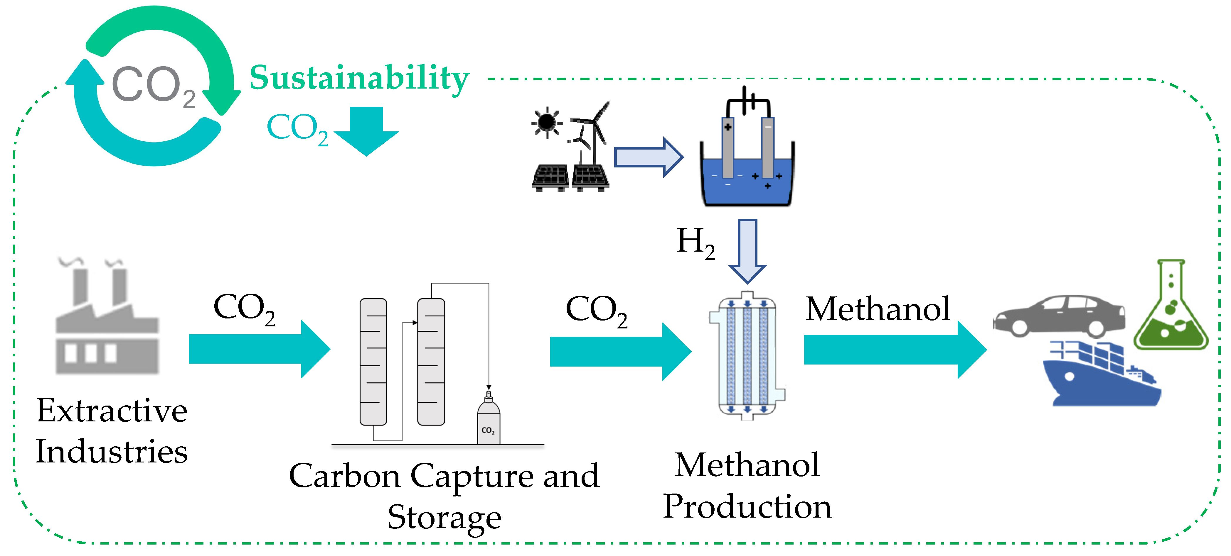
Table 1.
Main characteristics of operating CCS plants globally in 2021 [9].
Table 1.
Main characteristics of operating CCS plants globally in 2021 [9].
| CCS Plant | Location | Starting Date | Main Processes | Capacity (Mtpa CO2) |
|---|---|---|---|---|
| Terrell NG Processing Plant | United States | 1972 | NG Processing | 0.50 |
| Εnid Fertilizer | United States | 1982 | Fertilizer Production | 0.20 |
| Shute Creek Gas Processing Plant | United States | 1986 | NG Processing | 7.00 |
| MOL Szank field CO2 EOR | Hungary | 1992 | NG Processing | 0.16 |
| Sleipner CO2 Storage | Norway | 1996 | NG Processing | 1.00 |
| Great Plains Synfuels Plant & Weyburn-Midale | United States | 2000 | Synthetic NG | 3.00 |
| Core Energy CO2-EOR | United States | 2003 | NG Processing | 0.35 |
| Sinopec Zhongyuan CCUS | China | 2006 | Chemical Production | 0.12 |
| Snøhvit CO2 Storage | Norway | 2008 | NG Processing | 0.70 |
| Arkalon CO2 Compression Facility | United States | 2009 | Ethanol Production | 0.29 |
| Century Plant | United States | 2010 | NG Processing | 5.00 |
| Petrobras Santos Basin Pre-Salt Oil Field CCS | Brazil | 2011 | NG Processing | 4.60 |
| Bonanza BioEnergy CCUS EOR | United States | 2012 | Ethanol Production | 0.10 |
| Coffeyville Gasification Plant | United States | 2013 | Fertilizer Production | 0.90 |
| Air Products Steam Methane Reformer | United States | 2013 | Hydrogen Production | 1.00 |
| PCS Nitrogen | United States | 2013 | Fertilizer Production | 0.30 |
| Boundary Dam 3 CCUS Facility | Canada | 2014 | Power Generation | 1.00 |
| Quest | Canada | 2015 | Hydrogen Production | 1.20 |
| Uthmaniyah CO2-EOR Demonstration | Saudi Arabia | 2015 | NG Processing | 0.80 |
| Karamay Dunhua Oil Technology CCUS EOR | China | 2015 | Methanol Production | 0.10 |
| Abu Dhabi CCS | United Arab Emirates | 2016 | Iron And Steel Production | 0.80 |
| Illinois Industrial CCS | United States | 2017 | Ethanol Production | 1.00 |
| CNPC Jilin Oil Field CO2 EOR | China | 2018 | NG Processing | 0.60 |
| Gorgon Carbon Dioxide Injection | Australia | 2019 | NG Processing | 4.00 |
| Qatar LNG CCS | Qatar | 2019 | NG Processing | 2.20 |
| Alberta Carbon Trunk Line—North West Redwater Sturgeon Refinery CO2 Stream | Canada | 2020 | Hydrogen Production | 1.60 |
| Alberta Carbon Trunk Line with Nutrien CO2 Stream | Canada | 2020 | Fertilizer Production | 0.30 |
Table 2.
Capture efficiencies of various primary amine solvents in CCS systems.
| Solvent | CO2 Content (%) | Capture Efficiency (%) | Reference |
|---|---|---|---|
| 30 wt% MEA 40 wt% MEA | 6.6 vol | 90.0 86.9 | [18] |
| 30 wt% MEA | 14.2 | 90.0 | [19] |
| 13–27 wt% MEA 8–27 wt% DGA | 7 wt | 95.0 88.0 | [20] |
Table 3.
Capture efficiencies of various secondary and tertiary amine solvents in CCS systems.
| Solvent | CO2 Content (%) | Capture Efficiency (%) | Reference |
|---|---|---|---|
| DEA | 15 vol | 85.0 | [26] |
| MMEA EMEA | 15 | 92.0 92.4 | [25] |
| MDEA | 16.27 | 90.0 | [29] |
| MDEA/PZ | 12 vol | 90.0 | [30] |
Table 4.
Regeneration energy for innovative solvents.
| Solvent | CO2 Content (%) | Capture Efficiency (%) | Regeneration Energy (MJ/kg CO2) | Reference |
|---|---|---|---|---|
| MEA | - | 90 | 3.8 | [33] |
| Potassium taurate | 90 | 2.9 | ||
| 30% MEA | 12.8 | - | 4.5 | [34] |
| 30% SG | 5.7 | |||
| Potassium Glycinate/Sarcosinate + GBIG | 3.4 |
Table 5.
Performance of CMR reactors for WGS reaction.
| Membrane | H2O:CO Ratio | Temp. (°C) | Pressure (bar) | CO Conversion (%) | H2 Recovery (%) | H2 Purity (%) | Reference |
|---|---|---|---|---|---|---|---|
| Pd-based | 2.5:1 | 440 | 20 | 84.9 | 42.8 | 99.5 | [41] |
| Pd-based | 1.3:1 2:1 | 450 | 14.4 | 96.0 94.0 | 85.0 78.0 | - | [42] |
| Silica | - | 300 | 3.05 | 95–97.0 | 60.0 | 94 | [43] |
| Silica | 1:1 4:1 | 300 250 | - | 80.0 29.0 | - | - | [44] |
Table 6.
Performance of Cu-based catalysts for CO2 hydrogenation.
| Catalysts | H2:CO2 Ratio | Temperature (°C) | Pressure (bar) | CO2 Conversion (%) | MeOH Selectivity (%) | Catalyst Cost (€/kg cat.) | Reference |
|---|---|---|---|---|---|---|---|
| Cu/plate ZnO/Al2O3 | 2.2:1 | 270 280 270 280 | 45 | 10.9 12.0 15.5 14.7 | 72.7 71.6 64.5 63.3 | ~18.1 | [54] |
| 2.5:1 | |||||||
| CuO/ZnO/Al2O3 | 3:1 | 230 | 1 75 | 3.1 11.9 | 5.3 47.1 | [55] | |
| Cu/ZnO/Al2O3 | 10:1 | 260 | 360 | 65.8 | 77.3 | [56,57] |
Table 7.
Performance of catalysts for RWGS reaction.
| Catalyst | H2:CO2 Ratio | Temperature (°C) | CO2 Conversion (%) | CO Selectivity (%) | Catalyst Cost (€/kg cat.) | Reference |
|---|---|---|---|---|---|---|
| Cu/ZnO/Al2O3 Ru-Cu/ZnO/Al2O3 | 4:1 | 500 | 17.0 46.0 | 100 | ~18.1 | [57,63] |
| Pt/Al2O3 | 3:2.1 | 500 300 | 34.0 6.0 39.0 15.0 | 100 | 6520 | [64,65] |
| Pt/TiO2 | 500 300 | - | ||||
| Pt/TiO2 | 3:1 | 600 | 56.0 | 100 | - | [66] |
| Ni/Ce0.75Zr0.25O2 | 3:1 | 700 | 62.5 | 99.5 | - | [67] |
Table 8.
Effect of CO2:CO ratio in the production of MeOH for various catalysts.
| Catalyst | CO2:CO Ratio | Temperature (°C) | Carbon Conversion to MeOH (%) | Catalyst Cost (€/kg cat.) | Reference |
|---|---|---|---|---|---|
| Cu/ZnO-based | 2:28 | 250 | 69.7 | - | [68] |
| No CO | 9.7 | - | |||
| CuO/ZnO/Al2O3 | 1:9 | 250 | >50 | 18.1 | [57,69] |
| No CO | <20 |
Table 9.
Global warming potential of CO2 to MeOH conversion processes.
| CO2 to MeOH Conversion Processes | Global Warming Potential [kg CO2 eq/kg MeOH] | Life Cycle Identification | Reference |
|---|---|---|---|
| Coal gasification conversion | 17.7 | 1 kg MeOH production ReCiPe midpoint impact assessment | [78] |
| CO2 hydrogenation | 10.7 | ||
| Coke coking conversion | 2.90 | ||
| Photocatalytic conversion | 2.28 | ||
| CO2 hydrogenation (nuclear and solar thermal energy) | 1.67 | ||
| Amine-based CCS + CO2 hydrogenation | 1.05 | 1000 kg CCU products IPCC, 2013 | [79] |
| Production from syngas | 2.002 | ||
| Production from NG | ~0.9 | 1 kg MeOH production ecoinvent 3.1 | [80] |
| Direct air capture + CO2 hydrogenation | ~0.5 | ||
| No direct air capture + CO2 hydrogenation | <0 |
Disclaimer/Publisher’s Note: The statements, opinions and data contained in all publications are solely those of the individual author(s) and contributor(s) and not of MDPI and/or the editor(s). MDPI and/or the editor(s) disclaim responsibility for any injury to people or property resulting from any ideas, methods, instructions or products referred to in the content. |
© 2023 by the authors. Licensee MDPI, Basel, Switzerland. This article is an open access article distributed under the terms and conditions of the Creative Commons Attribution (CC BY) license (https://creativecommons.org/licenses/by/4.0/).
Share and Cite
MDPI and ACS Style
Peppas, A.; Kottaridis, S.; Politi, C.; Angelopoulos, P.M. Carbon Capture Utilisation and Storage in Extractive Industries for Methanol Production. Eng 2023, 4, 480-506. https://doi.org/10.3390/eng4010029
AMA Style
Peppas A, Kottaridis S, Politi C, Angelopoulos PM. Carbon Capture Utilisation and Storage in Extractive Industries for Methanol Production. Eng. 2023; 4(1):480-506. https://doi.org/10.3390/eng4010029
Chicago/Turabian StylePeppas, Antonis, Sotiris Kottaridis, Chrysa Politi, and Panagiotis M. Angelopoulos. 2023. "Carbon Capture Utilisation and Storage in Extractive Industries for Methanol Production" Eng 4, no. 1: 480-506. https://doi.org/10.3390/eng4010029