Pre-Operative Modeling of Transcatheter Mitral Valve Replacement in a Surgical Heart Valve Bioprosthesis


1
Department of Engineering, Viale delle Scienze, Ed.8, University of Palermo, 90128 Palermo, Italy
2
Department for the Treatment and Study of Cardiothoracic Diseases and Cardiothoracic Transplantation, IRCCS-ISMETT, via Tricomi n.5, 90127 Palermo, Italy
*
Author to whom correspondence should be addressed.
Prosthesis 2020, 2(1), 39-45; https://doi.org/10.3390/prosthesis2010004
Submission received: 27 February 2020
/
Revised: 9 March 2020
/
Accepted: 17 March 2020
/
Published: 20 March 2020
(This article belongs to the Section Bioengineering and Biomaterials)
Abstract
:Obstruction of the left ventricular outflow tract (LVOT) is a common complication of transcatheter mitral valve replacement (TMVR). This procedure can determine an elongation of an LVOT (namely, the neo-LVOT), ultimately portending hemodynamic impairment and patient death. This study aimed to understand the biomechanical implications of LVOT obstruction in a patient who underwent TMVR using a transcatheter heart valve (THV) to repair a failed bioprosthetic heart valve. We first reconstructed the heart anatomy and the bioprosthetic heart valve to virtually implant a computer-aided-design (CAD) model of THV and evaluate the neo-LVOT area. A numerical simulation of THV deployment was then developed to assess the anchorage of the THV to the bioprosthetic heart valve as well as the resulting Von Mises stress at the mitral annulus and the contract pressure among implanted bioprostheses. Quantification of neo-LVOT and THV deployment may facilitate more accurate predictions of the LVOT obstruction in TMVR and help clinicians in the optimal choice of the THV size.
1. Introduction
The evolution of catheter-based structural interventions has given patients less invasive alternatives to surgery; however, the current generation of transcatheter heart valves (THV) is not specifically designed for mitral position implantation and has an intrinsic geometry that may make mitral implantation suboptimal [1,2]. Indeed, while the term “transcatheter mitral valve replacement” (TMVR) is often used for the implantation of a dedicated transcatheter mitral valve in a native mitral anatomy, aortic transcatheter heart valves (THVs) are frequently used for transcatheter valve replacement in degenerated bioprosthetic mitral valves (i.e., valve-in-valve) [3,4]. However, one of the main problems of TMVR for a valve-in-valve procedure is the obstruction of the left ventricular outflow tract (LVOT) [5]. Specifically, the implanted THV can generate a protrusion of the THV wall into the left ventricle that can inhibit the blood flow from circulating in the distal ascending aorta. A small outflow tract geometry will create a region of turbulent flow distal to the narrowing, causing a large drop in pressure beneath the aortic valve and ultimately determining sub-aortic stenosis when the residual LVOT cross-sectional area, also known as neo-LVOT, is about 185 mm2 [6]. The main consequence of LVOT obstruction is the presence of complications for the patients that require further intervention or another therapeutic strategy.
Pre-procedural cardiac computed tomography angiography (CTA) is the main tool to estimate the anatomical suitability of the bioprosthesis for TMVR and quantify the neo-LVOT area after TMVR. Clinicians cannot account for computer simulations to pre-operatively plan the optimal deployment of THV in the mitral valve and therefore evaluate the obstruction into LVOT.
In recent years, many studies on computer simulation of the valve dynamics have been reported to provide valuable information on the functional analysis of native and THV as well as the relationship between mechanical stresses and disease progression [7,8,9,10,11]. Numerical simulations are also being used for the initial optimization and design of THV before the prototypes are built, and expensive experimental and animal evaluations have been conducted [12,13]. This can potentially reduce the time-to-market application of THV in clinical practice. The validation of simulation results is still an important issue to rapidly transfer the application of computer simulation in daily clinical practice to help clinicians in their clinical decision-making process.
In this study, we present the computational modeling of TMVR in a patient with a failed bioprosthetic heart valve. Specifically, we first segmented the heart anatomy of the patient including the presence of the Edwards Carpentier bioprosthetic heart valve using the medical imaging software Mimics (Materialise, Belgium). The Edwards Sapien 3 Ultra THV was then simulated to compute the neo-LVOT. A numerical analysis of the THV deployment is presented.
2. Material and Methods
2.1. Anatomic Reconstruction
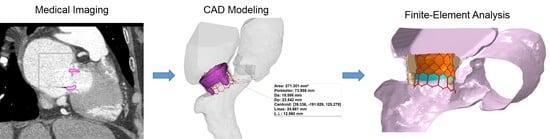
The patient case was a 74-year-old man presenting mitral valve failure of a previously treated bioprosthetic heart valve. CTA imaging was performed for this patient using a 64 detector-row CT scanner. Volumetric CT images in standard DICOM format were imported in Mimics to reconstruct the left ventricle, left atrium, and aortic root anatomy in terms of the spatial position and dimension by applying different gray values and multiple masks based on different Hounsfield unit thresholds. Segmentation was performed by semi-automatic thresholding operation followed by manual mask editing and morphological operation including cropping, erosion, and smoothing, as done previously by our group [14,15,16,17,18]. The bioprosthetic heart valve was distinctly reconstructed using a different mask. Figure 1 shows the heart anatomy as reconstructed from CTA images, while Figure 2 shows the reconstruction of the surgical bioprosthetic heart valve and annular dimension.
The geometrical model of THV was acquired with a high-resolution micro-CT scanner as described in our previous study [15]. The computer-aided-design model (CAD) of THV was imported as STL file in Mimics, and the THV was then positioned. The framework of basic steps of CAD modeling for neo-LVOT quantification is based on the approach developed by Blanke and collaborators [6]. These consisted of the segmentation of the mitral annulus, an assessment of the mitral trajectory, the virtual positioning of THV, the generation of the neo-LVOT centerline, and the quantification of neo-LVOT area.
2.2. Computational Modeling
The computational approach consisted of a finite-element analysis of THV deployment in the failed bioprosthetic heart valve. Both the heart anatomy and the bioprosthesis were respectively meshed with triangular shell and tetrahedral elements using ICEM software (ANSYS v.18, ANSYS, Inc., USA). Bioprosthetic valve leaflets were modeled using a general 3D parametric geometry of the native aortic valve and meshed with structured solid elements [19]. Nearly 60,000 structured-hexahedral solid elements with reduced integration and hourglass control (C3D8R) were used to discretize the metallic THV frame. As stents are loaded dominantly in bending, the fully integrated linear hexahedron element (C3D8) is not suited for the S3 THV analysis, so we used the reduced integration (C3D8R) with only one integration point at the center of the element. This C3D8R is inexpensive and has strain-free hourglass modes when loaded in bending. We used four elements through the S3 stent thickness to mitigate potential problems. Hourglass control is easy to use with relatively low artificial energy. After crimping of the device, the sealing skirt was modeled closing cell geometries with several surfaces build at mid-thickness of the THV frame. These surfaces representing the sealing skirt were discretized with triangular shell elements and a uniform thickness of 0.1 mm. The balloon model developed here was based on the Edwards Novaflex delivery system, which was photographed at the know scale. The balloon’s geometrical profile was realized in Rhinoceros (McNeil, USA) by revolution around the axis to create the balloon surface. The latter had a thickness of 0.1 mm and was meshed with membrane elements (M3D4) to reduce computational cost.
For the sake of simplicity, the heart was modeled as a linear-elastic material with a thickness of 4 mm and a density (D) of 1060 kg/m3. For the S3 Ultra, Von Mises plasticity and isotropic hardening were adopted to model the cobalt-chromium alloy frame [20], while an elasto-plastic stress-strain model was used for the polyethylene terephthalate material of the sealing skirt [21,22]. The aortic and bioprosthetic valve leaflets as well as the balloon were modeled with linear-elastic material properties (D = 1060kg/m3). Table 1 summarizes material parameters for each component of TMVR simulation.
Numerical analysis was performed in the ABAQUS/Explicit solver to account for a non-linear problem including large deformation and complex contacts [23,24]. The THV was crimped by a rigid dodecahedral surface gradually moved along the radial direction from the initial device diameter (i.e., 23 and 26) to the final diameter of 4.5 mm. This surface was meshed using 1500 structured-quadrilateral surface elements with reduced integration and a material density of 7000 kg/m3. A frictionless contact was defined between the crimping surface and the S3 Ultra, while tie contact conditions were used to fix the skirt surfaces to the THV frame. Balloon deflation was simulated through radial displacement of a cylindrical crimper and by constraining distal ends in all directions. The deformed configuration of the S3 Ultra THV was placed on the deflated balloon, and the assembly was then imported in the heart model. Both frictionless and “hard” normal behavior contact conditions were adopted for the interaction between S3 Ultra and balloon. For the expansion, the fluid-cavity-based model was employed to warrant a more realistic volume-controlled inflation and account for the over-expansion done during clinical procedures. Fluid-cavity material properties were manually calibrated by several simulations to ensure that the fluid filling volume leads to the nominal diameter expansion of the S3 Ultra [15]. As boundary conditions, distal ends of the left atrium and ascending aorta were fixed in all directions, while the expandable balloon was allowed to rotate during inflation.
3. Results and Discussion
Figure 3 shows the relative position of THV in the heart anatomy as done according to the clinical guideline and cardiologist’s suggestion. The optimal implantation height of the THV on the bioprosthetic heart valve was with 1/3 of the height in the left ventricle. We found that the area of the neo-LVOT is about 271 mm2, and this value is quite higher than current clinical guidelines for TMVR. Indeed, we show that the neo-LVOT area is higher than the clinical cut-off of 100 mm2 [1], which is considered a predictor of adverse outcomes related to neo-LVOT. Bioprosthetic valve leaflets longer than the implanted THV can also lead to prolapse into the neo-LVOT or infolding into the THV. The risk of life-threatening neo-LVOT obstruction is exaggerated when the aortic and mitral annular planes are acutely angulated rather than parallel, when the interventricular septum bulges toward the LVOT and when the implant extends or flares into the left ventricle.
Figure 4A shows the deformed shape of TMVR as deployed on the bioprosthetic heart valve after numerical simulation. A good fixation of THV on the bioprosthetic heart valve can be observed, and this discourages the presence of a paravalvular leak after the implantation [25]. Figure 4B shows the obstruction induced by the THV in a plane orthogonal to the aortic root. This could be the blood flow pumped by the left ventricle to the distal ascending aorta and other vessels. Finally, the map of Von Mises stress of the heart is shown as an indicator of the stress at the mitral valve annulus (see Figure 5A). Contact pressure between the bioprosthetic heart valve and the deployed THV demonstrated that the bioprosthesis serves as the anchor zone for the THV.
There are several limitations in this study, including the numerical assumption and material description. Frictionless and “hard” contact conditions were adopted due to the lack of knowledge of the friction coefficient and to warrant the normal direction during simulation. These assumptions can influence the resulting Von Mises stress distribution of the S3 device, although this study was mainly focused on the deformed shape of the deployed S3 THV rather than the resulting stress distribution. Although stress distributions at the mitral valve annulus were in agreement with those reported for the simulation of the transcatheter aortic valve implantation by our group [15] and those of other groups [20,25,26,27,28,29], the heart and mitral valve annulus structure is complex and characterized by a heterogeneous, hyperplastic, and anisotropic material with limited knowledge of material descriptors and constitutive behavior.
4. Conclusions
The patient-specific approach developed here has allowed us to elucidate the biomechanical implications of the neo-LVOT as determined by a prolonged THV to treat a failed bioprosthetic heart valve. Moreover, the approach can help clinicians in the optimal choice of the THV size by the pre-operative planning of a TMVR procedure. This is particularly relevant in TMVR, where LVOT obstruction is associated with a high rate of procedural adverse events. The simulation of THV deployment was based on finite-element analyses inspired by the modeling of transcatheter aortic valve implantation and includes the presence of the expandable balloon and the fluid-cavity approach for a faithful replicate of the clinical procedure. There are areas for improvements in our modeling framework, and further validation of our results are also warranted to confirm the efficacy of TMVR in patients with less suitable left ventricular anatomy.
Author Contributions
Conceptualization: S.P.; data curation: C.G.; formal analysis: S.P.; methodology: S.P. and C.G.; resources: C.G.; software: S.P.; validation: C.G.; writing—original draft: S.P.; writing—review & editing: C.G. All authors have read and agreed to the published version of the manuscript.
Funding
This research received no external funding.
Conflicts of Interest
The authors declare that there is no conflict of interest.
References
- Yoon, S.H.; Bleiziffer, S.; Latib, A.; Eschenbach, L.; Ancona, M.; Vincent, F.; Kim, W.K.; Unbehaum, A.; Asami, M.; Dhoble, A.; et al. Predictors of Left Ventricular Outflow Tract Obstruction After Transcatheter Mitral Valve Replacement. JACC Cardiovasc. Interv. 2019, 12, 182–193. [Google Scholar] [CrossRef] [PubMed]
- Alsidawi, S.; Eleid, M.F.; Rihal, C.S.; Nkomo, V.T.; Pislaru, S. Significant LVOT obstruction after mitral valve in ring procedure. Eur. Heart J. Cardiovasc. Imaging 2015, 16, 1389. [Google Scholar] [CrossRef] [PubMed] [Green Version]
- Yoon, S.H.; Whisenant, B.K.; Bleiziffer, S.; Delgado, V.; Schofer, N.; Eschenbach, L.; Fujita, B.; Sharma, R.; Ancona, M.; Yzeiraj, E.; et al. Transcatheter Mitral Valve Replacement for Degenerated Bioprosthetic Valves and Failed Annuloplasty Rings. J. Am. Coll. Cardiol. 2017, 70, 1121–1131. [Google Scholar] [CrossRef] [PubMed]
- Leipsic, J.; Blanke, P. Predicting Left Ventricular Outflow Tract Obstruction After Transcatheter Mitral Valve Replacement: From Theory to Evidence. JACC Cardiovasc. Interv. 2019, 12, 194–195. [Google Scholar] [CrossRef]
- Wang, D.D.; Eng, M.; Greenbaum, A.; Myers, E.; Forbes, M.; Pantelic, M.; Song, T.; Nelson, C.; Divine, G.; Taylor, A.; et al. Predicting LVOT Obstruction After TMVR. JACC Cardiovasc. Imaging 2016, 9, 1349–1352. [Google Scholar] [CrossRef]
- Blanke, P.; Naoum, C.; Dvir, D.; Bapat, V.; Ong, K.; Muller, D.; Cheung, A.; Ye, J.; Min, J.K.; Piazza, N.; et al. Predicting LVOT Obstruction in Transcatheter Mitral Valve Implantation: Concept of the Neo-LVOT. JACC Cardiovasc. Imaging 2017, 10, 482–485. [Google Scholar] [CrossRef]
- Chandran, K.B. Role of Computational Simulations in Heart Valve Dynamics and Design of Valvular Prostheses. Cardiovasc. Eng. Technol. 2010, 1, 18–38. [Google Scholar] [CrossRef] [Green Version]
- Aggarwal, A.; Aguilar, V.S.; Lee, C.H.; Ferrari, G.; Gorman, J.H.; Gorman, R.C.; Sacks, M.S. Patient-Specific Modeling of Heart Valves: From Image to Simulation. Funct. Imaging Model. Heart Int. Workshop FIMH Proc. 2013, 7945, 141–149. [Google Scholar] [CrossRef]
- Sacks, M.S.; Yoganathan, A.P. Heart valve function: A biomechanical perspective. Philos. Trans. R. Soc. Lond. Ser. B Biol. Sci. 2007, 362, 1369–1391. [Google Scholar] [CrossRef] [Green Version]
- Rabbah, J.P.; Saikrishnan, N.; Siefert, A.W.; Santhanakrishnan, A.; Yoganathan, A.P. Mechanics of healthy and functionally diseased mitral valves: A critical review. J. Biomech. Eng. 2013, 135, 021007. [Google Scholar] [CrossRef]
- Sacks, M.; Drach, A.; Lee, C.H.; Khalighi, A.; Rego, B.; Zhang, W.; Ayoub, S.; Yoganathan, A.; Gorman, R.C.; Gorman Iii, J.H. On the simulation of mitral valve function in health, disease, and treatment. J. Biomech. Eng. 2019. [Google Scholar] [CrossRef] [PubMed]
- Zakerzadeh, R.; Hsu, M.C.; Sacks, M.S. Computational methods for the aortic heart valve and its replacements. Expert Rev. Med. Devices 2017, 14, 849–866. [Google Scholar] [CrossRef] [PubMed]
- Khalighi, A.H.; Rego, B.V.; Drach, A.; Gorman, R.C.; Gorman, J.H., 3rd; Sacks, M.S. Development of a Functionally Equivalent Model of the Mitral Valve Chordae Tendineae Through Topology Optimization. Ann. Biomed. Eng. 2019, 47, 60–74. [Google Scholar] [CrossRef] [PubMed]
- D’Ancona, G.; Amaducci, A.; Rinaudo, A.; Pasta, S.; Follis, F.; Pilato, M.; Baglini, R. Hemodynamic Predictors of a Penetrating Atherosclerotic Ulcer Rupture using Fluid-Structure Interaction Analysis. ICVTS 2013, 17, 576–578. [Google Scholar]
- Pasta, S.; Cannata, S.; Gentile, G.; Di Giuseppe, M.; Cosentino, F.; Pasta, F.; Agnese, V.; Bellavia, D.; Raffa, G.M.; Pilato, M.; et al. Simulation study of transcatheter heart valve implantation in patients with stenotic bicuspid aortic valve. Med. Biol. Eng. Comput. 2020. [Google Scholar] [CrossRef]
- Pasta, S.; Gentile, G.; Raffa, G.M.; Bellavia, D.; Chiarello, G.; Liotta, R.; Luca, A.; Scardulla, C.; Pilato, M. In Silico Shear and Intramural Stresses are Linked to Aortic Valve Morphology in Dilated Ascending Aorta. Eur. J. Vasc. Endovasc. Surg. 2017, in press. [Google Scholar] [CrossRef]
- Rinaudo, A.; D’Ancona, G.; Lee, J.J.; Pilato, G.; Amaducci, A.; Baglini, R.; Folli, C.; Pilato, M.; Pasta, S. Predicting Outcome of Aortic Dissection with Patent False Lumen by Computational Flow Analysis. Cardiovasc. Eng. Technol. 2014, 5, 176–188. [Google Scholar] [CrossRef]
- Pasta, S.; Agnese, V.; Di Giuseppe, M.; Gentile, G.; Raffa, G.M.; Bellavia, D.; Pilato, M. In Vivo Strain Analysis of Dilated Ascending Thoracic Aorta by ECG-Gated CT Angiographic Imaging. Ann. Biomed. Eng. 2017. [Google Scholar] [CrossRef]
- Shen, X.; Wang, T.; Cao, X.; Cai, L. The geometric model of the human mitral valve. PLoS ONE 2017, 12, e0183362. [Google Scholar] [CrossRef]
- Morganti, S.; Conti, M.; Aiello, M.; Valentini, A.; Mazzola, A.; Reali, A.; Auricchio, F. Simulation of transcatheter aortic valve implantation through patient-specific finite element analysis: Two clinical cases. J. Biomech. 2014, 47, 2547–2555. [Google Scholar] [CrossRef]
- Kleinstreuer, C.; Li, Z.; Basciano, C.A.; Seelecke, S.; Farber, M.A. Computational mechanics of Nitinol stent grafts. J. Biomech. 2008, 41, 2370–2378. [Google Scholar] [CrossRef] [PubMed]
- Rinaudo, A.; Raffa, G.M.; Scardulla, F.; Pilato, M.; Scardulla, C.; Pasta, S. Biomechanical implications of excessive endograft protrusion into the aortic arch after thoracic endovascular repair. Comput. Biol. Med. 2015, 66, 235–241. [Google Scholar] [CrossRef] [PubMed]
- Morlacchi, S.; Chiastra, C.; Gastaldi, D.; Pennati, G.; Dubini, G.; Migliavacca, F. Sequential structural and fluid dynamic numerical simulations of a stented bifurcated coronary artery. J. Biomech. Eng. 2011, 133, 121010. [Google Scholar] [CrossRef] [PubMed]
- Lee, J.J.; D’Ancona, G.; Amaducci, A.; Follis, F.; Pilato, M.; Pasta, S. Role of computational modeling in thoracic aortic pathology: A review. J. Card. Surg. 2014, 29, 653–662. [Google Scholar] [CrossRef]
- Lavon, K.; Marom, G.; Bianchi, M.; Halevi, R.; Hamdan, A.; Morany, A.; Raanani, E.; Bluestein, D.; Haj-Ali, R. Biomechanical modeling of transcatheter aortic valve replacement in a stenotic bicuspid aortic valve: Deployments and paravalvular leakage. Med. Biol. Eng. Comput. 2019, 57, 2129–2143. [Google Scholar] [CrossRef]
- Luraghi, G.; Migliavacca, F.; Garcia-Gonzalez, A.; Chiastra, C.; Rossi, A.; Cao, D.; Stefanini, G.; Rodriguez Matas, J.F. On the Modeling of Patient-Specific Transcatheter Aortic Valve Replacement: A Fluid-Structure Interaction Approach. Cardiovasc. Eng. Technol. 2019, 10, 437–455. [Google Scholar] [CrossRef]
- Bianchi, M.; Marom, G.; Ghosh, R.P.; Rotman, O.M.; Parikh, P.; Gruberg, L.; Bluestein, D. Patient-specific simulation of transcatheter aortic valve replacement: Impact of deployment options on paravalvular leakage. Biomech. Model. Mechanobiol. 2019, 18, 435–451. [Google Scholar] [CrossRef]
- Auricchio, F.; Conti, M.; Morganti, S.; Reali, A. Simulation of transcatheter aortic valve implantation: A patient-specific finite element approach. Comput. Methods Biomech. Biomed. Eng. 2014, 17, 1347–1357. [Google Scholar] [CrossRef]
- Finotello, A.; Morganti, S.; Auricchio, F. Finite element analysis of TAVI: Impact of native aortic root computational modeling strategies on simulation outcomes. Med. Eng. Phys. 2017, 47, 2–12. [Google Scholar] [CrossRef]
Figure 1.
CTA images showing the axial, sagittal, and coronal view as well as the 3D heart anatomy after segmentation.
Figure 1.
CTA images showing the axial, sagittal, and coronal view as well as the 3D heart anatomy after segmentation.

Figure 2.
3D segmentation of the bioprosthetic heart valve and dimension of the mitral valve annulus.
Figure 2.
3D segmentation of the bioprosthetic heart valve and dimension of the mitral valve annulus.

Figure 3.
3D model of the THV as virtually implanted in the heart valve bioprosthesis and dimension of the mitral valve annulus.
Figure 3.
3D model of the THV as virtually implanted in the heart valve bioprosthesis and dimension of the mitral valve annulus.

Figure 4.
(A) The deformed shape of the deployed THV as obtained from numerical simulation and (B) a view from the aortic root showing the neo-LVOT obstruction.
Figure 4.
(A) The deformed shape of the deployed THV as obtained from numerical simulation and (B) a view from the aortic root showing the neo-LVOT obstruction.

Figure 5.
(A) A map of Von Mises stress of the heart anatomy and (B) a map of contact pressure between the THV and the bioprosthetic heart valve.
Figure 5.
(A) A map of Von Mises stress of the heart anatomy and (B) a map of contact pressure between the THV and the bioprosthetic heart valve.


Table 1.
Material parameters adopted for each component of TMVR simulation; E = Young modulus; ν = Poisson coefficient; σy = yield stress; σult = ultimate tensile stress; εp = plastic strain; μ = viscosity; D = density.
Table 1.
Material parameters adopted for each component of TMVR simulation; E = Young modulus; ν = Poisson coefficient; σy = yield stress; σult = ultimate tensile stress; εp = plastic strain; μ = viscosity; D = density.
| E(MPa) | ν | σ y (MPa) | σult (MPa) | εp | μ (Pa s) | D (kg/m3) | Element Number (thousand) | |
|---|---|---|---|---|---|---|---|---|
| Heart | 4 | 0.49 | 1,060 | 65.6–68.5 | ||||
| S3 Ultra | 233 x103 | 0.35 | 414 | 930 | 0.45 | 8,000 | 59.2 | |
| Sealing Skirt | 55 | 0.49 | 6.6 | 6.6 | 0.6 | 8,000 | 3.5–3.7 | |
| Bioprosthesis | 8 | 0.45 | 1,060 | 10.5–12.5 | ||||
| Balloon | 600 | 0.3 | 1,060 | 62.8 | ||||
| Fluid | 3.7 × 10⁻³ | 1,060 | 301.1 |
© 2020 by the authors. Licensee MDPI, Basel, Switzerland. This article is an open access article distributed under the terms and conditions of the Creative Commons Attribution (CC BY) license (http://creativecommons.org/licenses/by/4.0/).
Share and Cite
MDPI and ACS Style
Pasta, S.; Gandolfo, C. Pre-Operative Modeling of Transcatheter Mitral Valve Replacement in a Surgical Heart Valve Bioprosthesis. Prosthesis 2020, 2, 39-45. https://doi.org/10.3390/prosthesis2010004
AMA Style
Pasta S, Gandolfo C. Pre-Operative Modeling of Transcatheter Mitral Valve Replacement in a Surgical Heart Valve Bioprosthesis. Prosthesis. 2020; 2(1):39-45. https://doi.org/10.3390/prosthesis2010004
Chicago/Turabian StylePasta, Salvatore, and Caterina Gandolfo. 2020. "Pre-Operative Modeling of Transcatheter Mitral Valve Replacement in a Surgical Heart Valve Bioprosthesis" Prosthesis 2, no. 1: 39-45. https://doi.org/10.3390/prosthesis2010004