1. Introduction
Robotic cotton harvesting is a promising technology with the potential to improve harvesting efficiency, preserve cotton fiber quality, reduce yield losses, and promote sustainable cotton production [
1,
2]. However, despite researchers’ continuous efforts aimed at its development, cotton harvesting robots are not yet available commercially [
3,
4]. Like other harvesting robots, cotton harvesting robots rely on four major subsystems: sensing, planning, navigating, and manipulating. The sensing system detects and localizes obstacles and cotton bolls. The planning system processes sensor data to calculate an optimized path to reach the target. The navigating system guides the robot towards the target. The manipulating system consists of actuators and end-effectors to perform the task of cotton picking.
The control systems, navigation algorithm, and objection detection algorithms utilized in various agricultural and non-agricultural robots [
5,
6,
7,
8,
9,
10,
11,
12,
13] can also be adapted for cotton harvesting robots. Several research articles have focused on distinct sub-components of a robotic cotton harvesting system, such as the development of a cotton boll detection model [
14,
15,
16,
17,
18,
19], navigation and path planning algorithms [
20,
21,
22,
23,
24,
25], and end-effector designs [
26,
27,
28,
29,
30]. However, few articles have comprehensively addressed all components of robotic harvesting systems and evaluated their combined performance in cotton fields.
Fue et al. [
31] developed a cotton harvesting robot consisting of a center-articulated hydrostatic rover and a 2-axis Cartesian manipulator equipped with a small roller having several retracting tines as an end-effector and a vacuum system to transport cotton bolls. The rover employed a YOLOv3-tiny model (performance metrics not reported) and a stereo camera for cotton boll detection. In field test, the rover achieved a cycle time of 38 s and action success rate of 78.5% using one-boll picking with a time approach. Similarly, Gharakhani et al. [
28] developed a prototype robotic cotton harvester with a Cartesian-type robotic arm with three degrees of freedom and a custom three-fingered pinned belt end-effector. The study utilized a YOLOv4-tiny network with a precision of 0.95, a recall of 0.93, and an
[email protected] of 0.95 for cotton boll detection. In laboratory settings, they achieved a picking ratio of 72% of seed cotton with an average cycle time of 8.8 s per boll. Other robotic cotton harvesters, like CHAP HUSKY [
32] and Green Robot Machinery [
33], have not explicitly reported their harvesting performance yet. CHAP HUSKY was a proof-of-concept of a cotton harvesting robot, which had a single vacuum suction port as an end-effector positioned where most cotton bolls were expected. It lacked a cotton boll detection system. Green Robot Machinery, a startup company in India, has been developing an autonomous robotic arm with an end-effector consisting of three small rollers with tines, all mounted on a semi-autonomous electric farm vehicle. This system includes a stereo camera for cotton boll detection and a 3-degree-of-freedom robotic arm with an end-effector and a vacuum suction system to transfer picked cotton to the collecting bin.
Except for CHAP HUSKEY, all the aforementioned robotic cotton harvesting systems are consistently designed and operated based on the approach of detecting individual cotton bolls and harvesting them one at a time. These cotton harvesting systems often have slow harvesting times per boll due to the extended time taken by actuators to approach and retract for picking individual cotton bolls, as well as due to the limited computational speed of embedded computers in the robots. With slow harvesting speed and a low picking ratio, these robotic cotton harvesters are not yet feasible for deployment in the fields.
With the aim of making robotic cotton harvesting faster and more efficient, Thapa et al. [
34] introduced a novel approach in 2022: harvesting multiple cotton bolls at a time. Based on this approach, they designed an end-effector with a roller containing several tines and a pair of guiding bars equipped on a 2-axis Cartesian manipulator to gather multiple cotton bolls together at the end-effector while the robot moves down the row. They tested the end-effector’s harvesting performance manually adjusting the end-effector height. Multiple passes in each row were made at different levels, and without a cotton detection model. In the field test, they achieved a cycle time of 5.5 s per boll, with a picking ratio of 40.7%. This harvesting time is significantly faster than other robotic harvesting systems but requires significant improvement in the picking ratio.
The aim of this study was to improve the harvesting performance of the robot used in Thapa et al. [
34]. The end-effector was modified with a wider and longer roller to increase the percentage of the cotton plant being harvested. Additionally, a pullback reel was added to assist in holding cotton plants upright while the robot harvests down a row. A vision-based cotton detection model using YOLOv4 [
35] was implemented, and a new cotton boll clustering algorithm was developed using hierarchical agglomerative clustering to group detected cotton bolls. A harvesting algorithm was set up to harvest cotton clusters in multiple passes. A Proportional–Integral–Derivative Controller (PID) was implemented to adjust the end-effector height according to the targeted cotton cluster height. For simplicity, a straight-line path planning algorithm was implemented. Finally, the robotic cotton harvesting system was integrated onto the same robotic platform used in Thapa et al. [
34], incorporating the modified end-effector, pullback reel, cotton detection model, cotton clustering algorithm, and straight-line navigation algorithm. The robot’s cotton-harvesting performance was assessed in terms of the picking ratio and harvesting time per boll in the laboratory and field settings. Finally, the performance was compared with that of Thapa et al. [
34] and other robotic cotton harvesting systems.
This study provides a comprehensive insight into robotic cotton harvesting based on the multi-boll harvesting at a time approach, demonstrating that this method is significantly faster than the other approach of picking one boll at time. This emphasizes the potential of this method for future robotic cotton harvesting technology.
2. Materials and Methods
2.1. Robotic Platform
The robotic platform employed in this study was the Small Red Rover, equipped with electric 4-wheel Ackerman-steering, as shown in
Figure 1. The robot measured 123 cm in length, 76 cm in width, and 116 cm in height, and it navigated between crop rows in the field. The rover had four wheels, each powered by a 250 W Pride Mobility wheelchair motor (Pride Mobility, Exeter, PA, USA). A linear servo (HDA8-50, ServoCity, Winfield, KS, USA) was connected to the front wheels for steering. The rover was equipped with Cartesian-type robotic arms with two degrees of freedom: the
x-axis (horizontal) for left and right movement, and the
z-axis (vertical) for up and down motion. The
y-axis degree of freedom is achieved through the rover’s forward and backward movement. These arms are situated at the front side of the rover, with a cotton harvesting end-effector attached to the right end of the
x-axis arm. A vacuum hose connects the end-effector to a vacuum canister, which is positioned at the top-front section of the rover and serves as the collection point for the harvested cotton bolls. A stopper board equipped with Pullback Reel (custom-built, fingered roller, driven by a 12 DC geared motortor—more details provided in
Section 2.7) was attached to the right side of the rover making a gap of 15 cm from the end-effector to the stopper board. The function of the stopper board and the pullback reel was to avoid cotton plants falling sideways and keep them upright while harvesting down the row.
2.2. Sensors
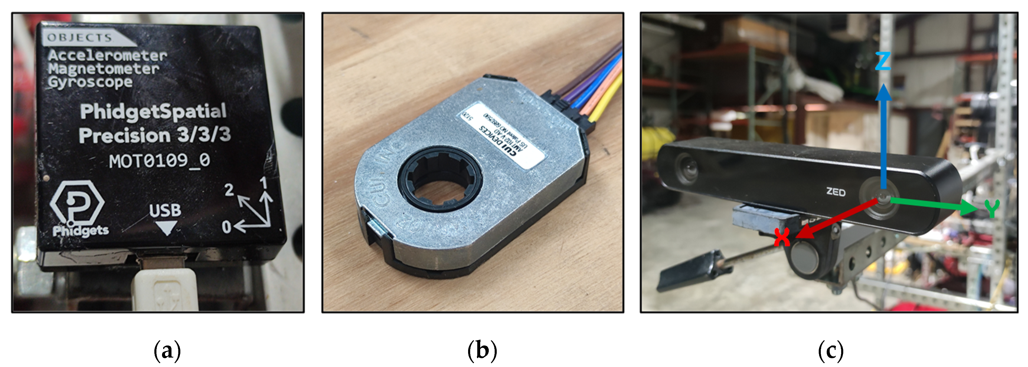
Although the rover had a GNSS module, this study utilized only two Inertial Measurement Units (IMUs), two back wheel encoders, and a ZED2 stereo-camera (shown in
Figure 2a–c). The positions of the sensors installed on the rover are shown in
Figure 1.
The rover’s orientation was monitored using two IMUs (PhidgetSpatial Precision 3/3/3 high-resolution, MOT0109_0, Phidgets Inc., Calgary, AB, Canada), each equipped with a 3-axis accelerometer, 3-axis gyroscope, and 3-axis compass to accurately determine the rover’s positioning (shown
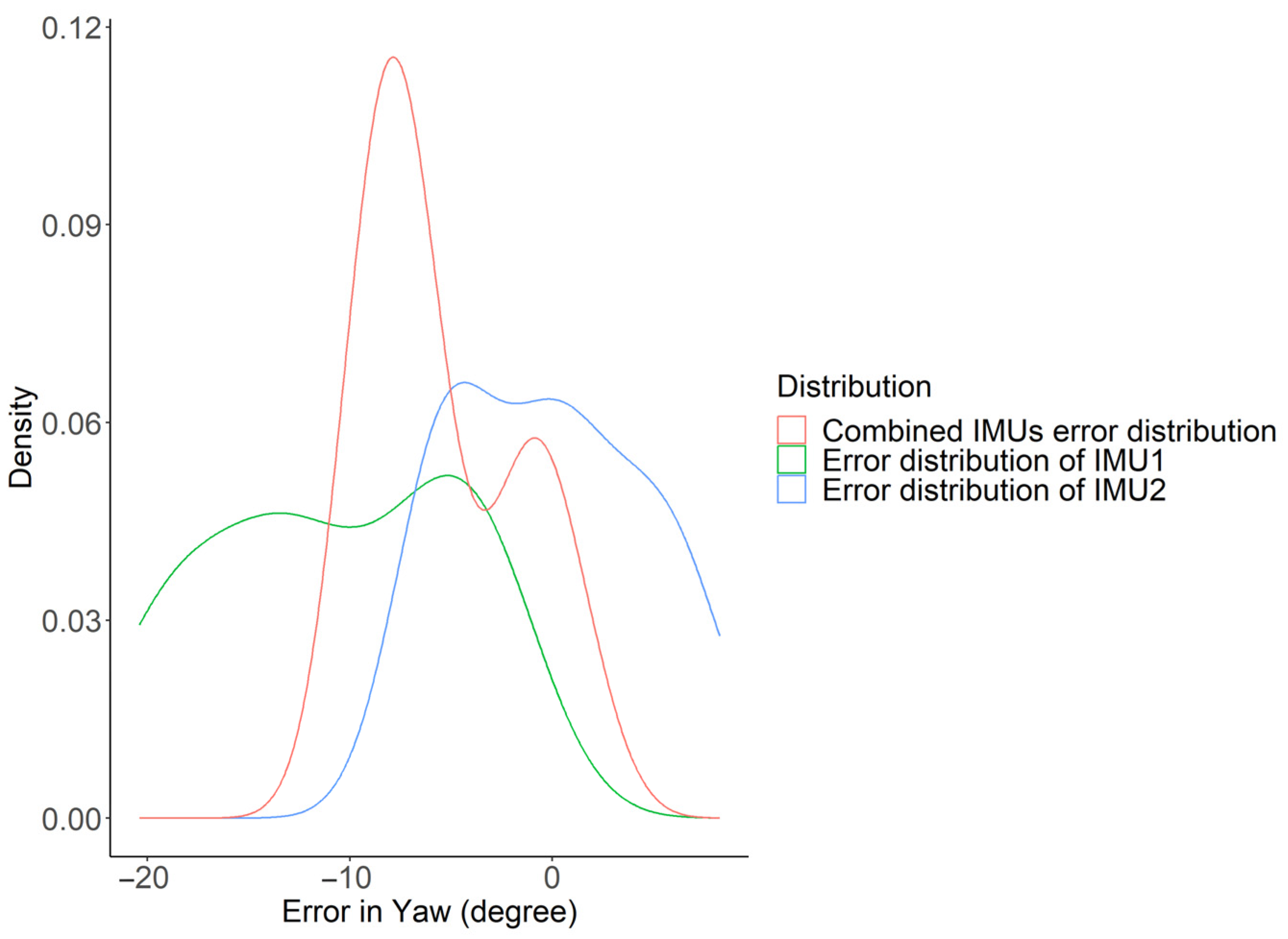
Figure 2a). The IMUs measured the change in yaw of the rover and were fused to produce an accurate measurement. The distributions of the IMUs’ errors are shown in
Figure 3. The first IMU had a wider error distribution with a mean error of −10.69° in yaw change and a standard deviation of 6.13°. The second IMU’s error distribution was comparatively narrower and more accurate than the first, with a mean error of −0.161° in yaw change and a standard deviation of 4.70°. The combined IMUs had a narrower error distribution than the individual ones, with an average error of −5.42° in yaw change and a standard deviation of 3.75°. Combining the two IMUs resulted in a narrower error distribution with a reduced standard deviation.
Each of the two back wheels was connected to a quadrature rotary encoder (CUI AMT 102, CUI Devices, Lake Oswego, OR, USA) to provide feedback on how far the wheels had rotated (
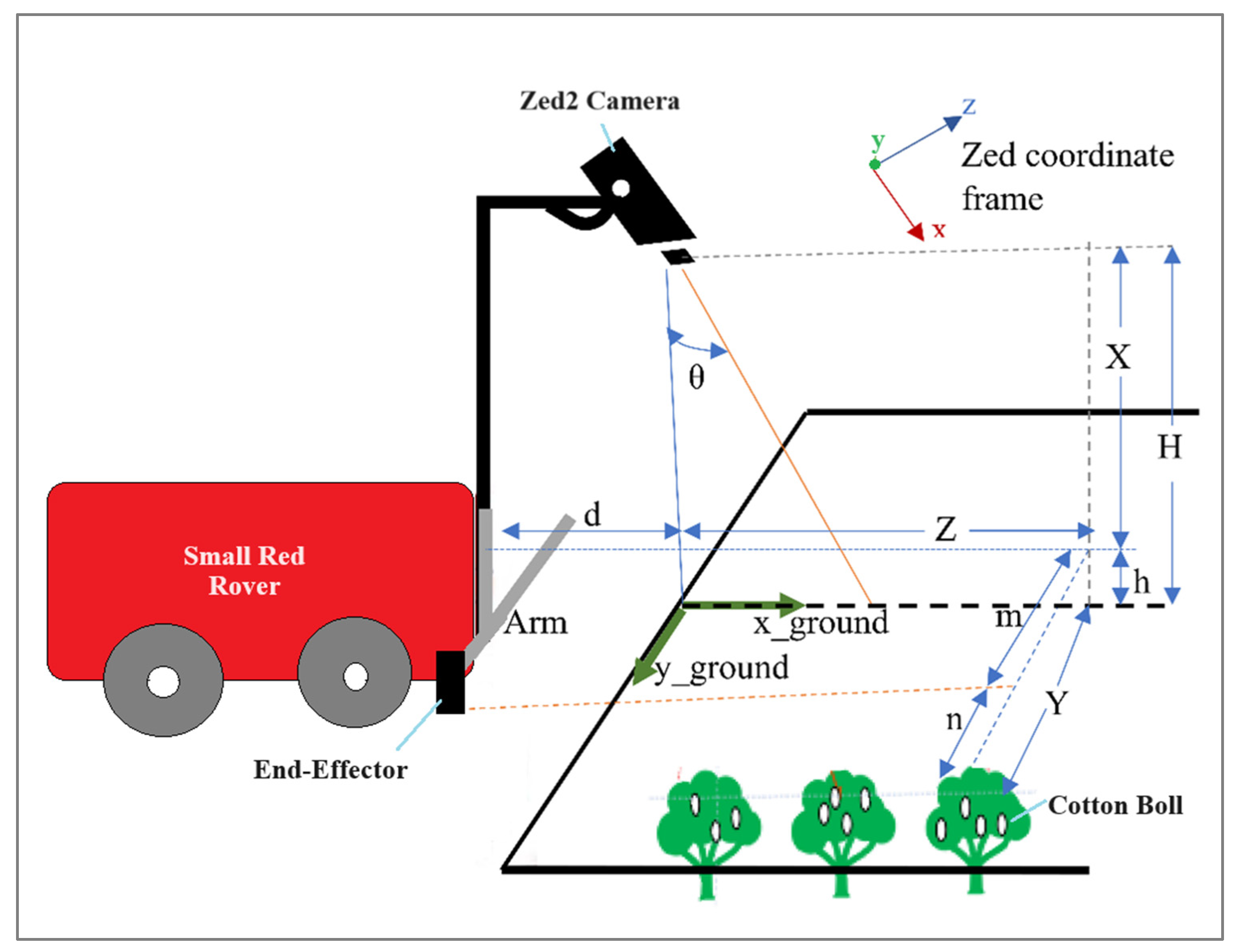
Figure 2b). A Zed2 stereo-camera (Stereo labs Inc., San Francisco, CA, USA) was mounted facing toward the ground, at the central line of the rover, at a height of H = 134 cm and d = 65 cm ahead of the robotic arm’s plane, and at a θ = 20° angle about
y-axis of the camera’s coordinate frame. This camera featured two image sensors, enabling the capture of standard RGB images, depth images, and 3D point clouds. The camera also had internal IMUs for tracking its orientation, but it was not implemented to monitor the rover’s orientation because implementing two external IMUs provided more consistent values, as well as easier calibration and sensor fusion. The camera was used for detecting cotton bolls and determining the 3D coordinates of the detected cotton bolls relative to the camera’s coordinate system (as shown in
Figure 2c and
Figure 4). The camera published ROS topics for RGB images and point clouds, which were subscribed to by the cotton detection node from the embedded computer. The Zed2 camera published a 3D point cloud containing (x, y, z) coordinates that represented the center of the detected cotton boll from the camera’s reference coordinate. The camera was tilted at an angle of θ = 20° along the
y-axis in the xz-plane (as shown in
Figure 4).
The true perpendicular distances were obtained using the rotation matrix by y as follows:
the perpendicular distances (X, Y, Z) are obtained by
If H represents the height of camera from the ground, d represents the distance between the arm and the camera along the rover’s central line, and m represents the distance between the end-effector and the camera along the side of the rover, then the following distances are calculated as follows:
This study only used the height (h) of cotton bolls as an input variable to divide detected cotton bolls into clusters. For each cluster, the total lint was correlated with the sum of the area of bounding boxes in that cluster. The end-effector approached the target cluster that had the maximum sum of the bounding boxes’ area.
2.3. Master Robot Controller
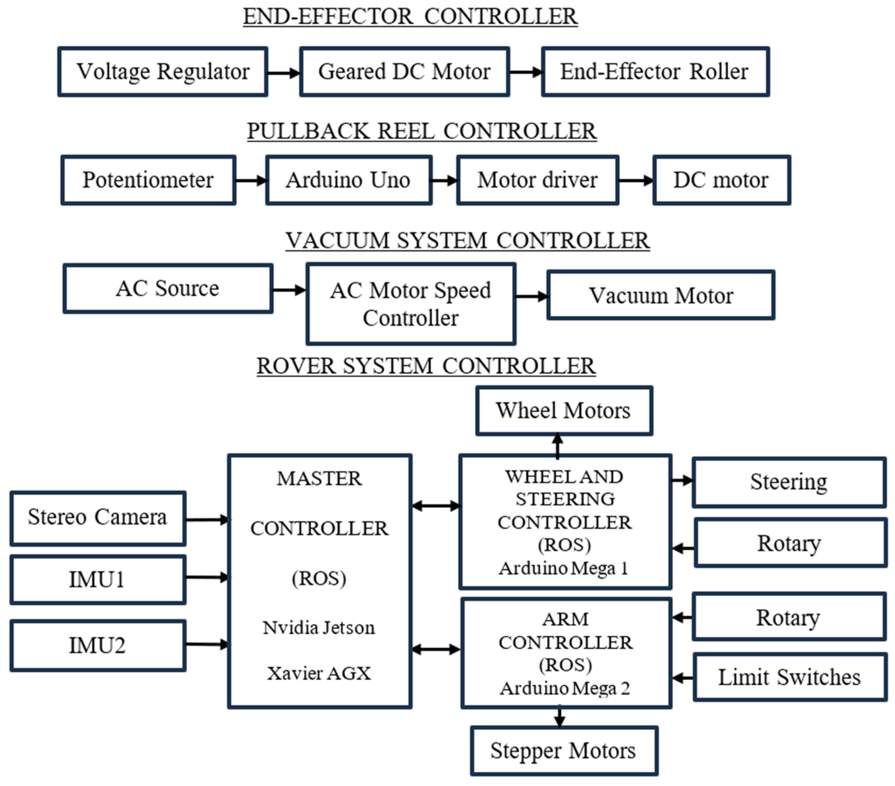
The rover featured four primary controllers (as shown in
Figure 5), responsible for overseeing all the sensors and actuators integrated into the rover. These controllers included a master controller responsible for coordinating all robot activities, a rover controller dedicated to navigation tasks, and an arm controller designed for manipulation purposes. Additionally, there were three other independent controllers: the end-effector controller, the pullback reel controller, and the vacuum system controller.
The central processing unit of the robot was an Nvidia Jetson Xavier AGX embedded computer (Nvidia Corporation, Santa Clara, CA, USA), featuring an 8-core ARM v8.2 64-bit CPU, 32 GB of RAM, and a 512-core Volta GPU with tensor cores. It provided the necessary computational power for the development and deployment of comprehensive AI-driven robotic applications while consuming minimal power (less than 30 watts). The computer performed various tasks such as receiving and interpreting sensors data like RGB images & point clouds from the stereo camera and IMUs, running deep learning models for object detection, straight line path planning, and managing Arduino Mega microcontrollers (Arduino LLC, Somerville, MA, USA) connected directly to sensors and actuators by transmitting commands and receiving sensor data. Communication between the computer and other components occurred through the Robotic Operating System (ROS-Noetic) [
36].
2.4. Rover Controller
To control the driving and steering of the rover, an Arduino Mega 1 microcontroller was used, as shown in
Figure 5. The controller communicated with the embedded computer using ROS. The rover employed Ackerman steering geometry to track its position, orientation, and velocity. The front wheels were steered using a linear servo (HDA8-50, ServoCity, Winfield, KS, USA). For manual control of the rover, an IRIS+ RC transmitter (3D Robotics, Berkeley, CA, USA) and FrSky X8R receiver (FrSky Electronic Co., Ltd., Shenzhen, China) were connected to the Arduino Mega 1.
A PID (Proportional, Integral, and Derivative) controller [
37] was implemented to maintain the desired velocity of the rover. This controller consistently computes the disparity between an intended reference value and a measured parameter, subsequently adjusting the control output by considering three pre-configured gains: proportional, integral, and derivative. The output of the PID controller sends the command to the rover’s motor divers to reach the desired target (in this case, velocity). If the difference or error between the current value and the desired value is e(t), the motor command u(t) is calculated as
where constants
,
, and
are proportional, integral, and derivative gain, respectively. To maintain the rover’s desired speed, the error signal
is calculated as the difference between the set point (which is the number of wheel encoder pulses required to travel a certain distance) and the actual number pulses reading from the wheel encoder. The PID controller works to minimize this error signal. The manual tuning technique was adopted to determine the value for these PID gains. First, the
value was increased until the rover exhibited oscillations with neutral stability, while keeping Ki and
values to zero. Then,
was increased until the rover oscillated around the setpoint. Finally,
was adjusted until the system settled at the given setpoint quickly.
2.5. Arm Controller
The robotic manipulator comprised a 2D cartesian system consisting of two linear rails (Igus drylin
® belt drive, ZAW-1040 horizontally oriented, and ZLW-1040 vertically oriented) driven by two Igus drylin
® NEMA 17 stepper motors (Igus Inc., East Providence, RI, USA). These motors were controlled by two SureStep STP-DRV-6575 stepper drivers (AutomationDirect, Cumming, GA, USA) and featured internal rotary encoders to track the position of the rails. The arms were controlled by an Arduino Mega 2 microcontroller (as show in
Figure 5), which communicated with the embedded computer via ROS. The master controller published the arm setpoints, to which the arm controller subscribed. Simultaneously, the arm controller published the arm position topics, to which the master controller subscribed. The arm controller implemented the PID controller to achieve the desired arm position. In this study, the vertical arm and forward rover movement were only used to reach the targeted cluster of cotton bolls. The master controller published the centroidal height of a cluster of cotton bolls, to which the arm controller subscribed it as vertical arm setpoint. The horizontal arm was set a fixed distance from the central line of cotton row. The forward movement of the rover brought the end-effector to the targeted centroidal point.
2.6. End-Effector and Its Control
The End-effector (version 2) used in this study was an improved version of the end-effector (version 1) used in [
34].
Table 1 shows the design changes from version 1 to version 2. The working mechanism of the end-effector was very similar to the end-effector used in [
31,
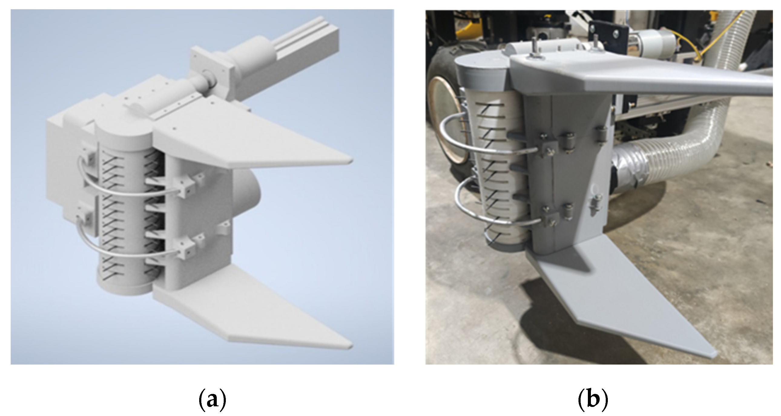
33]. It consisted of a roller (24.5 cm long, 7.62 cm diameter, Polylactic acid PLA material) with fourteen tine rings, each having four tines (4.8 cm long from the center, 0.183 cm diameter, steel ASTM A229 material). A metal bevel gear (10 mm face width, 1.5 Module, 3:1 speed ration, carbon steel material) was attached to the roller and driven by a metal pinion gear (10 mm face width.1.5 module, 3:1 speed ratio, carbon steel material) coupled with a DC motor (XD-60GA775, 24 V, 35 W, 500 RPM, 4.7 Nm stall torque, Shandong Xinda Motor, Shandong, China). A new set of upper and lower guides with 10° angles was incorporated into the end-effector, aiding in guiding and gathering multiple cotton bolls towards the roller tines. Additionally, two aluminum rings were added to protect the tines from encountering the main stem of the cotton plant, thereby preventing damage. The CAD model and the fabricated assembly of the end-effector are shown in
Figure 6. Its detailed drawings are in
Supplementary Material (Figure S1).
The end-effector was mounted on the right side of the horizontal arm of the rover. The roller of the end-effector was set to rotate in a counter-clockwise direction. When a cotton boll encounters the roller tines, it either gets stripped off or only the fiber gets pulled inside the end-effector’s casing, from which a vacuum system transports the harvested bolls to the collecting chamber. The end-effector controller was an independent unit (as shown in
Figure 5), which had an end-effector geared DC motor powered by a 24 V DC voltage regulator. A switch was implemented in between the end-effector motor and the power supply, which was turned on and off at the start and end of the harvesting process manually.
2.7. Pullback Reel and Its Controller
To enhance the cotton harvesting process and improve the interaction between the end-effector and the cotton bolls, a vertical Pullback Reel has been integrated at the stop board (as shown in
Figure 7). This reel plays a crucial role in gently pulling back the cotton plants as the rover moves down the row. This action helps the plants remain upright and properly positioned when the end-effector encounters them. The reel was equipped with fifteen metal fingers (three fingers in five vertical shafts each of length 22 cm, each finger of length 6.8 cm), created using 3D printing technology. These fingers were designed to grab plant stalks, providing the necessary support for pulling the plants backward. The reel had a diameter of 20 cm and was placed 31 cm above the ground.
The Reel’s rotation was powered by a DC geared motor (BRINGSMART, DC12V16RPM, with a no load current of 350 mA, rated speed of 14 RPM, rated torque of 25 kg.cm, rated current of 1.6 A, gear ration of 1:5, and rated power of 19.2 W, BRINGSMART, Jinzhou, China), controlled by an independent Arduino Uno (as shown in
Figure 5) and a motor driver. A potentiometer was connected to the Arduino Uno to regulate the speed of the pullback reel. After several preliminary tests, 11 RPM was found to be suitable for the reel. The Arduino Uno was configured to maintain the reel’s speed throughout the harvesting process. Detailed drawings are included in
Supplementary Material (Figure S1).
2.8. Vacuum Conveying System
To transport harvested cotton from the end-effector to the collecting chamber, a vacuum system was used. The vacuum system was a CRAFTSMAN model (Stanley Black & Decker, New Britain, CT, USA)) with the following specifications: 120 V AC power supply, 850 watts of power, an airflow rate of 85 CFM (cubic feet per minute), and a sealed suction pressure of 12.9 kPa. A 182.9 cm (6 ft) long vacuum hose (flexible, clear polyvinyl chloride (PVC) material) with a diameter of 7.62 cm (3-inch) was used to connect the end-effector and the collecting chamber. The collecting chamber was positioned at a height of 137 cm (4.5 ft) as shown in
Figure 1. An independent AC motor speed controller (as shown in
Figure 5) was employed to adjust the vacuum motor to the desired speed.
2.9. Cotton Detection Model and Clustering Algorithm
YOLOv3 [
38], YOLOv4 [
35], and YOLOv4-tiny detection models were trained to detect cotton bolls in the field using a total of 3530 annotated images, out of which, 90% were used for training and 10% were used for testing. A majority of the annotated images were used from the study [
31], which contained original and augmented images. Some augmented images were filtered out and some new images were added to the cotton image dataset.
In terms of precision, YOLOv4 performed the best (shown in
Table 2), getting 6 frames per second (FPS) on the embedded computer, Jetson Xavier AGX. YOLOv3 got slightly lower precision metrics while achieving 7 FPS on the embedded computer. The lightweight YOLOv4-tiny was approximately 37.1% less precise than YOLOv4, while performing 2× faster than YOLOv4 on the embedded computer. As the algorithm used in this study to detect cotton bolls and divide them into clusters did not require higher FPS, YOLOv4 was selected for the cotton detection model.
Figure 8a shows the detection of cotton bolls using the YOLOv4 model.
The cotton detection model processed RGB images from the Zed2 stereo-camera, as shown in
Figure 8a, and sent the point clouds corresponding to the detected cotton bolls to a clustering algorithm, specifically the hierarchical agglomerative clustering algorithm [
39]. This algorithm divided the detected cotton bolls into clusters based on their height, as shown in
Figure 8b. In this representation, different colored circles represent different detected cotton bolls, with the size of the circles indicating the area of bounding box. Circles of the same color fall within the same cluster, and the cross marks represent the centroidal heights of individual clusters. The distribution of the circles illustrates the distances of the detected cotton bolls from the central-front line of the rover.
Figure 8a shows the detected cotton bolls, while
Figure 8b displays the distribution and clustering of the detected cotton bolls. In this case, the clustering algorithm divided the detected cotton bolls into three clusters represented by yellow, green, and purple circles, with the three cross marks denoting the centroidal heights of the individual clusters.
The number of clusters determined by the clustering algorithm relies on both the height of detected cotton bolls and the selected maximum distance threshold, which, in this case, was set to 30 cm. Cotton bolls within 30 cm of each other fall into the same cluster. The maximum distance threshold was chosen because the end-effector’s guide panels had 31 cm wide openings which could accommodate a cluster of cotton bolls whose size was 30 cm or less. The cluster with the highest area of bounding boxes was chosen as the target cluster to harvest. The clustering algorithm then sent the centroidal height of the target cluster as the setpoint height of the end-effector for harvesting.
The image frame obtained from the Zed2 stereo-camera was 1280 by 720 resolution. Targeted and untargeted cotton bolls were included in the frame. To concentrate on detecting cotton bolls of a desired location and determining clusters of the region only, a frame masking (rectangular, corner1: (450, 200) and corner2: (750, 600)) algorithm was implemented, which detected cotton bolls within a 75 cm × 108 cm window, 40 cm ahead of the end-effector, as shown in
Figure 9. This 40 cm of distance between the end-effector and the cotton cluster detecting window was selected so that the vertical arm could have enough time to raise or lower the end-effector to reach the centroidal setpoint height of the detected cluster of cotton.
2.10. Navigation in Cotton Fields
For simplicity, the rover was confined to moving in a straight line between rows of cotton fields. It navigated by following the straight path, employing a modified Dynamic Window Approach (DWA) path planning algorithm. This navigation section of work was adapted from Mwitta [
40]. The DWA algorithm is designed to determine optimal collision-free velocities for the robot’s navigation while considering the robot’s kinematics. DWA considers three key parameters for optimization. The first parameter is ‘Heading’, which measures how closely the robot’s current direction aligns with the targeted goal location. The second parameter is ‘Obstacle Distance’, which calculates the distance to the nearest obstacle along the trajectory. The third parameter is the forward velocity of the robot, with the algorithm aiming to select the highest permissible velocity for efficient movement. In this study, the robot exclusively followed a straight line, and obstacle avoidance was not a concern. Therefore, only the ‘Heading’ and ‘Velocity’ parameters were used to optimize the algorithm. The robot’s localization was achieved by monitoring the wheel encoder readings for position and IMUs for orientation. The DWA algorithm generated linear and angular velocities for the robot’s navigation based on its pose and the target goal along the straight line.
2.11. Overall Algorithm of the Robotic Cotton Harvesting
The overall harvesting algorithm for the rover is depicted in the flowchart (
Figure 10). At the start of the harvesting process, the Zed2 camera, end-effector motor, pullback reel motor, vacuum conveying system, and straight-line navigation algorithm were initialized. The end-effector motor, pullback reel, and vacuum convey system operated continuously and independently throughout the harvesting process, and they were manually turned off at the end of the harvest. Once the rover was initiated with the straight-line navigation algorithm, it autonomously moved in a straight line with an average velocity of 0.10 m/s until it was manually stopped. It was important for the rover to be aligned straight with the row of cotton plants at the beginning, as there was no feedback implementation to adjust the rover’s orientation based on the row direction. The Zed2 camera continuously streamed 1280p × 720p 15FPS RGB images along with point clouds. The cotton detection model, along with the hierarchical Agglomerative clustering algorithm, detected cotton bolls falling within the masking rectangle (as shown in
Figure 9). These bolls were divided into clusters, and their centroidal height was calculated. The detection model and clustering algorithm operated continuously, detecting, clustering, and determining the centroidal height of the best cluster (the cluster with the maximum sum of the area of bounding boxes, correlating with the cluster with the maximum number of cotton lint) at a rate of 4–5 FPS. While the target centroidal height was determined at that rate, it served as the setpoint height for the vertical robotic arm at 0.2 m distance intervals as the rover moved forward. In this manner, the robotic cotton harvester autonomously picked the cotton. After harvesting a row, the rover was set up again as previously described for the next row. At the conclusion of the harvesting process, all components were shut down manually.
2.12. Experimental Setups
Lab experiments and field experiments were conducted to assess the performance of the integrated robotic cotton harvesting system. The lab experiments were setup at Engineering Annex building, Tifton campus, University of Georgia, (31.475455° N, 83.528381° W), where three rows (each 152.4 cm (5 ft) long) of defoliated cotton plants were held upright using metal bars and clamps as shown in
Figure 11a. Similarly, for field tests, four rows (each of 304.8 cm (10 ft) long) of defoliated cotton plants were taken from the cotton field (31.4719165° N, 83.5279990° W) at Tifton campus, University of Georgia (as shown in
Figure 11b). Cotton was planted in the field at 2–3 seed/foot at 101.6 cm (40 inch) row spacing. In lab tests, the cotton plants were taken from the same field and those were set at two plants/foot.
In both the lab and field tests, each row underwent harvesting in four passes by the rover. During the 1st pass, cotton bolls from the left side of the row were harvested. In the 2nd pass, harvesting was conducted on the right side of the row. The 3rd pass saw the harvesting of cotton bolls from the left side of the row once again, and in the 4th pass, cotton bolls were harvested from the right side of the row, completing the harvesting cycle.
Before each observation, the total number of cotton bolls present in the row was counted. The rover was configured to move in a straight line along the row. The end-effector motor was activated with a 24 V DC supply, resulting in a roller speed of 180 RPM. The pullback reel’s motor was powered by a 12 V DC supply, rotating counterclockwise at 11.3 RPM. The vacuum conveying system was activated using a 100 V AC supply (regulated by a voltage regulator, ZOWZEA NHT-4000W, Shanghai Shouni Electrical Technology Co., Ltd, Shanghai, China), creating a suction pressure of 9.046 kPa (1.312 psi), an air velocity of 21.72 m/s, an airflow rate of 3.64 cubic meter per minute (128.63 CFM), and consuming approximately 725 W. RGB images and point cloud data were continuously streamed, and the cotton detection and clustering algorithms were loaded. The horizontal arm was positioned so that the end-effector’s frontal side was 48 cm away from the rover’s central line and had a 14 cm gap from the stopper board. With all systems set up for harvesting, autonomous mode was enabled, and the rover initiated forward movement. The vertical arm adjusted itself to match the centroidal height of the cotton cluster at 0.2 m intervals. This same procedure was followed for each pass and observation. For each pass, the time taken to harvest the cotton was recorded, and the harvested cotton was collected in separate bags. Dropped cotton bolls and unpicked cotton bolls from each row were also collected in separate containers.
Finally, the weights of seeded cotton bolls, both with and without burrs and branches, were recorded for each pass of every observation during both the lab and field tests. The harvesting performance of the integrated robotic harvesting rover was evaluated in terms of picking ratio and picking time per boll, following the methodology used in previous studies [
27,
34]. The picking ratio was determined by dividing the total weight of picked seeded cotton by the total weight of seeded cotton in the row (picked + unpicked + dropped). Harvesting time per boll was calculated by dividing the total time taken for four passes in a row by the total number of harvested cotton bolls for that row. The rover was manually turned and aligned straight with the harvesting row using the remote controller (RC transmitter) between each pass. The time taken for turning and aligning the rover was not considered in the harvesting time calculation.
3. Results
The raw data obtained from the lab and field tests of the integrated multi-boll robotic cotton harvester in the year 2023 are presented in
Appendix A (
Table A1 and
Table A2). The harvesting performance in terms of the picking ratio and picking time per boll for each row in the lab and field tests was calculated from the raw data and is presented in
Table 3. The table also includes the harvesting performance data for Version 1 robot tested by Thapa et al. [
34] in 2022 for the comparison purposes.
In the 2023 lab test, the integrated multi-boll robotic cotton harvester achieved an average picking ratio of 57.1%, with a standard deviation of 8.7%. In terms of harvesting speed, it achieved an average picking time of 2.5 s per boll, with a standard deviation of 0.45 s. In the field test, the robotic harvester achieved an average picking ratio of 56.0%, with a standard deviation of 6.2%, and it achieved an average picking time of 3.0 s per boll, with a standard deviation of 0.56 s. From the boxplot and T-test shown in
Figure 12a,b, the robotic harvester’s picking ratio and picking time per boll in the lab and field tests were not significantly different.
The Version 1 robot, as tested by Thapa et al. [
34] in 2022, achieved an average picking ration of 40.7% (SD 4.2) with the average picking time of 5.5 s (SD 1.97) per boll in the field. The harvesting performance of Version 1 robot are also included in
Table 3. Upon comparing the average picking ratio of the integrated robotic cotton harvester in the 2023 field test with that of the Version 1 robot tested by Thapa et al. [
34] in the 2022 field test, the integrated robotic cotton harvester developed in this study achieved a significantly higher picking ratio than the Version 1 robot (as depicted by
Figure 12c). Similarly, the integrated robotic cotton harvester achieved a significantly faster picking time per boll than the Version 1 robot (as represented by
Figure 12d). Overall, the integrated robotic cotton harvesting system was able to increase the picking ratio 16% more and reduce the average picking time per boll by about 46% (approximately 1.8 times faster picking time per boll) compared to the Version 1 robot.
While conducting lab tests of the robotic harvester, we observed that adding an inclined plane to the stopper board could potentially enhance harvesting performance by guiding cotton plants toward the end-effector. Therefore, following the lab tests, we formed a sheet metal into an inclined guide and added it to the stopper board, as shown in
Figure 13a,b.
4. Discussion
When comparing the performance of this integrated robotic harvesting system with previous version of the end-effector [
34], it is evident that the new system did not demonstrate improved harvesting performance in the lab setting. However, during field tests, this version of the harvesting system showed significant improvements. The robotic harvester had only one end-effector harvesting one side of a row in one pass. Implementing two end-effectors to harvest cotton from either side of the row simultaneously in one pass could potentially reduce the picking time per boll to nearly half the time achieved in this study.
The stripping mechanism of the end-effector resulted in the removal of some branches and burs during harvesting, leading to an average of 27.3% (SD 2.17) foreign materials (burrs and branches) in the lab tests. In the field tests, an average of 30.6% (SD 1.61) foreign materials were present in the harvested cotton.
Figure 13c illustrates the foreign materials found in the harvested cotton. These foreign materials also caused another issue: the blockage of the vacuum hose inlet and outlet, as shown in
Figure 13d,e. The design of the vacuum canister inlet port and the end-effector’s outlet port did not effectively handle these foreign materials. Replacing the end-effector’s stripping mechanism with a barbed spindle type of picking mechanism could help reduce the percentage of foreign materials in the harvested cotton. Additionally, the issue of vacuum hose blockage could be mitigated by properly designing the attachment of vacuum hoses to the inlet and outlet ports.
During both the lab and field tests, an average of 21.4% (SD 6.68) of seeded cotton bolls were inadvertently dropped during harvesting. This was likely due to the presence of only one end-effector on one side of the row and the use of a stopper board, which increased the likelihood of dropping cotton bolls with brittle branches. The brittleness of the stalks could be due to delayed harvest after defoliation. The tests were conducted around three weeks after defoliation. The dropping of cotton bolls due to brittle branches could be avoided by harvesting more closely aligned with defoliation timing. Another approach to mitigating these losses could involve employing two end-effectors on both sides of the cotton row. Alternatively, a new end-effector design could be developed to collect the dropped cotton bolls before they reach the ground, potentially leading to an improvement in the picking ratio.
5. Conclusions
In this study, a robotic multi-boll cotton harvester was developed, and its harvesting performance was tested. The end-effector used in the study [
34] was modified by designing longer, wider, and more powerful roller-tines, which were then fabricated. To enhance harvesting efficiency, a pullback reel with several fingers was designed to pull the cotton plant backward while the rover moved forward during the row harvest. The pullback reel was positioned on the stopper board, preventing cotton plants from falling towards the ground. To streamline the harvesting process, a pair of guide panels were incorporated at the top and bottom of the end-effector to collect multiple cotton bolls and direct them towards the roller. Additionally, a pair of aluminum rings were added at the front of the end-effector to protect the roller tines from the main stems of the cotton plants. Cotton boll detection and clustering were achieved through the implementation of the YOLOv4 cotton detection model and the Hierarchical Agglomerative clustering algorithm. A Zed2 stereo camera provided RGB images and point clouds to the detection model for accurate cotton detection and localization. The rover’s movement was managed using a modified Dynamic Window Approach (DWA) path planning algorithm, which facilitated straight-line movement. To transport harvested cotton bolls from the end-effector to the collecting chamber, a vacuum conveying system was employed.
After integrating all these sub-systems into the Small Red Rover platform, lab and field experiments were conducted to evaluate the harvesting performance of the developed system. In the lab tests, an average picking ratio of 57.1% (SD 8.7) was achieved, with an average picking time per boll of 2.5 s (SD 0.45). In the field tests, the average picking ratio was 56.0% (SD 6.16), and the average picking time per boll was 3.0 s. It is noteworthy that the performance of the robotic harvesting system in the lab setting did not show improvement over the previous version of the end-effector. However, in the field tests, the robotic harvesting system demonstrated significant improvements, achieving an approximately 16% higher picking ratio and reducing the picking time per boll by about 46%.
The primary objective of this study was to integrate the sub-components of a robotic cotton harvesting system and evaluate its harvesting performance, with a specific focus on the picking ratio and picking time per boll. The study’s results confirm the potential of a robotic cotton harvesting system designed to harvest multiple cotton bolls simultaneously to achieve significantly faster picking times. In fact, the robotic cotton harvesting system in this study outperformed other systems in terms of harvesting speed. To enhance the picking ratio, efforts should be directed toward reducing the dropping of cotton bolls during harvesting. One approach could involve using two end-effectors, one on each side of the row. Additionally, implementing a barbed spindle type of end-effector may help reduce the presence of foreign materials in the harvested cotton.


 ,
, 


