Tonal-Noise Assessment of Quadrotor-Type UAV Using Source-Mode Expansions


1
École Centrale de Lyon, Université de. Lyon, 36 Avenue Guy de Collongue, 69134 Écully, France
2
Department of Mechanical Engineering, Université de Sherbrooke, Sherbrooke, QC J1K 2R1, Canada
*
Author to whom correspondence should be addressed.
Acoustics 2020, 2(3), 674-690; https://doi.org/10.3390/acoustics2030036
Submission received: 8 August 2020
/
Revised: 3 September 2020
/
Accepted: 3 September 2020
/
Published: 17 September 2020
(This article belongs to the Special Issue Aeroacoustics of Turbomachines)
Abstract
:The present work deals with the modeling of the aerodynamic sound generated by the propellers of small-size drones, taking into account the effects of horizontal forward flight with negative pitch and of installation on supporting struts. Analytical aeroacoustic formulations are used, dedicated to the loading noise. The fluctuating lift forces on the blades are expanded as circular distributions of acoustic dipoles, the radiated field of which is calculated by using the free-space Green’s function. This provides descriptions of the sound field, valid in the entire space. The stationary mean-flow distortions responsible for the lift fluctuations and at the origin of the sound are estimated from existing numerical flow simulations and from ad hoc models. Installation and forward-flight effects are found to generate much more sound than the steady loading on the blades associated with thrust. Therefore, the models are believed reliable fast-running tools that could be used for preliminary low-noise design through repeated parametric calculations, or for noise-impact estimates corresponding to prescribed urban traffic.
1. Introduction
Small-to-medium size classes of flying objects or vehicles are likely to become part of everyday life in cities in the near future, relying on distributed electric propulsion. This includes drones (RPA for Remotely Piloted Aircraft, or UAV/S for Unmanned Aerial Vehicles/Systems, etc.) for delivery or oversight, on the one hand, and urban air vehicles, on the other hand. The common features of both are the multiple propeller units used to power the machine and the associated rotating-blade noise. The urban use of UAVs will be managable at a large scale only if automated fleet control is made available to fulfill obvious safety constraints. The other condition is that the increased acoustic nuisance for inhabitants is kept to an acceptable level [1,2,3]. In this context, manufacturers and town planners will need to predict the expected noise exposure corresponding to prescribed traffic scenarios. Such a task requires simple prediction tools, able to provide realistic estimates at low computational cost. The present work is dealing with an analytical approach meeting this need. Strong simplifications must be accepted on both the geometry and the flow features, for mathematical tractability. Therefore, the approach provides expressions of the sound field that are approximate but all the same relevant in terms of decibels. It must be kept in mind that very accurate flow and noise predictions are only achievable with numerical simulation strategies, once all geometrical details and operational regimes are defined. For the moderate subsonic Mach numbers of interest, a practical approach succeeding in UAV noise prediction is the Lattice–Boltzmann Method (LBM), as already reported by, for instance, Nardari et al. [4] and Casalino et al. [5]. However, the price to pay for accuracy is a higher computational cost. Furthermore, repeated numerical simulations cannot be performed at the early design stage when some details of the blade geometry are still unspecified or when too many sets of parameters must be explored. In contrast, analytical calculations can be performed at this stage, essentially because the addressed mechanisms do not crucially involve all geometrical details. Analytical models are the best suited candidates to select a class of performant individuals in an optimization algorithm, prior to running numerical tools for the final design step. They are appropriate as well for impact studies.
The physics of rotating-blade noise has been thoroughly studied in the past decades for aeronautical propulsion systems, cooling units and low-speed fans used in Heating, Ventilation and Air Conditioning (HVAC). Though the basic mechanisms are the same for all technologies, application to urban air vehicles and drones is much more recent. It deserves specific attention because of the involved special architectural features. The present approach is illustrated on the drone configuration made of four co-planar free-field rotors and called quadrotor, but it could be applied as well to any multi-rotor architecture. The choice of quadrotors is motivated by the fact that they will probably be of most general use in the future. Furthermore, they involve key aspects of fundamental interest, such as relative side-flow induced by horizontal flight and possible synchronization of pairs of rotors.
Rotating-blade noise includes tonal noise at multiples of the blade-passing frequency (BPF, rotational frequency multiplied by the blade number B), if the rotor blades are equally spaced, and broadband noise. Tonal noise is attributed to the steady-state aerodynamics of the blades, on the one hand, and to periodic variations of the aerodynamics of the blades with the period of rotation, on the other hand. The latter find their origin in all deviations from pure axisymmetry of the flow through a rotor disk, referred to as stationary distortions. They are typically induced by lateral flight and by recirculations inherent to the operational regimes. They are also induced by mean-flow distortions around neighboring surfaces, which is known as the aerodynamic installation effect. Broadband noise is associated with the turbulence in the flow. It is not addressed in the present study because of the widely reported high emergence of the tonal noise (see for instance [4,6,7,8]). Moreover, tonal noise induces a much higher perceived nuisance. It is most often the part of the acoustic signature that makes a rotating-blade technology identified. Typically, for small-size drones, it is heard as somewhat similar to the buzz of flying insects. The tonal noise from drones can also be attributed to specific features associated with the electric driving. Additional noise of electromechanical origin and irregularities of the rotating speed are recognized as significant contributions, as pointed out by McKay and Kingan [9]. Apart from its generation, rotating-blade noise is also scattered by the main body and struts of a drone, which a priori modifies the radiating properties in the environment. This is called the acoustic installation effect. This topic has been addressed for instance by Jiang et al. [10], assuming point monopoles at the rotor centers instead of more realistic distributed and rotating sources. Electric-motor induced noise and sound scattering are not considered in the present study, focussed on the primary aerodynamic noise generation and radiation. Apart from source modeling issues, assessing the noise impact in the environment also involves realistic propagation models that are beyond the scope of the present study. This aspect is addressed for instance by Bian et al. [11] and Casalino et al. [5].
The physical understanding of rotating-blade noise and the basis for its mathematical modeling are provided by Ffowcs Williams and Hawkings’ formulation of the acoustic analogy [12,13,14], which leads to the recognition of three basic components:
- -
- thickness noise associated with fluid-displacement effects around moving blades;
- -
- loading noise generated by the steady and unsteady blade forces, essentially the lift;
- -
- flow noise due to flow inhomogeneities around the blades.
For subsonically rotating thin blades, loading noise most often dominates (see, for instance, Lighthill [15] or Goldstein [14], Chapter 3). More precisely, in a purely axisymmetric flow, steady-loading noise and thickness noise are the only expected contributions. They are intrinsic to the design of the blades and are directly related to thrust. As such, they should be always considered together, because possibly of the same order of magnitude, at least if all radiation angles are taken into account (see for instance sound predictions for the two-bladed propellers of the light aircraft reported by Dahan et al. [16]). Thickness noise is modified in non-axial flows. Yet, it is ignored in the present work, mainly because it cannot be analytically predicted if the precise shape of the blades is unknown. In contrast, unsteady-loading noise estimates with analytical models only require the blade chord and the velocity triangle as input data. They are only related to zero-averaged periodic lift fluctuations. Unsteady-loading noise dominates for thin blades at low speeds as soon as the flow is significantly distorted. For this reason the present study is mainly focussed on unsteady-loading noise associated with mean-flow distortions. It is aimed at comparing it to steady-loading noise, and at demonstrating that steady-state aerodynamics is not essential for acoustic predictions. Thickness noise and flow noise are discarded from the analysis. Comparing steady-loading noise and unsteady-loading noise is of major interest for a proper assessment of drone impact on the environment. Indeed, changes of operational conditions, such as transitions from hover to advancing flight, turning manoeuvers and so on, are associated with changes in the acoustic signature because of variations in the aerodynamic loads. From the standpoint of manufacturers, the ranking of steady-loading noise and unsteady-loading noise contributions is essential when looking for low-noise design rules. The usual basic design achieved to reach targeted aerodynamic performances in terms of thrust is insufficient because it is only related to steady-loading noise. If noise enters the optimisation strategy as a criterion, unsteady loads must be considered as well. Consequently, the present work addresses realistic model distortions encountered in typical drone architectures, such as described in [6,17]. Two distortions are retained, namely the side-flow induced by advancing flight and the potential distortion around the supporting struts of a rotor.
A short description of the quadrotor architecture is provided in Section 2. The background for analytical models of the tonal loading noise is then presented in Section 3. The forward-flight effect on the noise of a quadrotor is predicted in Section 3.3, ignoring the strut-induced installation effect. Then the potential-distortion noise due to the vicinity of a rotor to its supporting strut is addressed separately in Section 3.4, implicitly in hover configuration. This allows estimating both effects independently. The separation appears questionable because the flow features in forward flight differ with and without the blockage effect of the struts. Yet it has a great interest for manufacturers. Typically, the rotor-strut distance can be adjusted depending on whether the potential interaction takes over forward-flight effect or not, according to model predictions. Concluding remarks are finally made about the use of the models for noise-impact assessment.
2. Basic Aerodynamic Features of Quadrotors
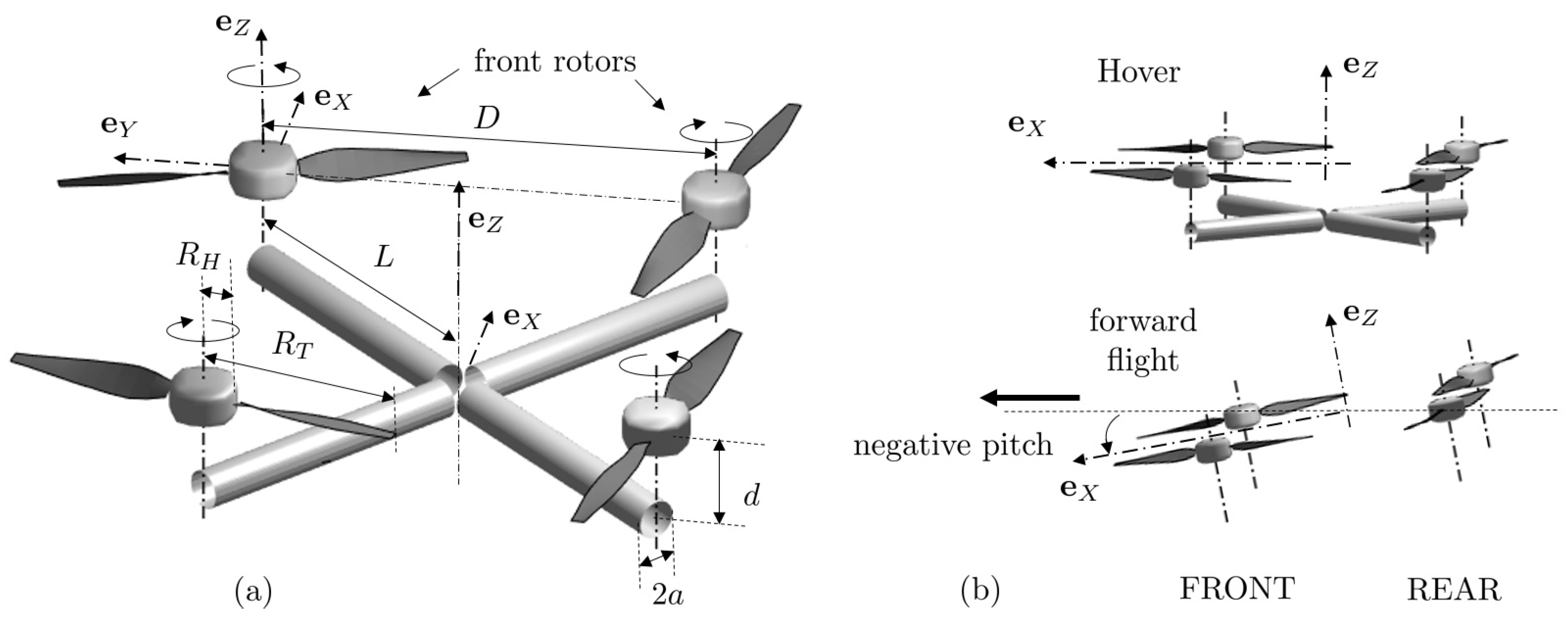
The basic architecture of a quadrotor is made of four co-planar rotors, the centers of which are at the corners of a square. This makes the blade-tip radius and either the rotor-to-rotor axis distance D or the center-to-rotor axis distance L first parameters of interest. Secondly, the rotors are installed on a frame, attached to a main body by radial struts. For a first insight into basic aeroacoustic properties, the struts can be assimilated to equivalent cylinders of circular cross-section, which defines as other key parameters the radius of the strut cross-section, a, and the distance between the strut axis and the mid-chord plane of the blades, d. The resulting generic arrangement is depicted in Figure 1. The rotors are assumed to radiate sound in free-field, which means that sound scattering by the struts is ignored. The struts are only accounted for by their potential flow distortion, as a possible source of sound, addressed in Section 3.4.
Two configurations are considered for the study. The configuration D1 is close to the well-documented drone Cyclone investigated by Misiorowski et al. [18] and to the one reported by Tinney and Sirohi [17]. The configuration D2 is more representative of the DJI Phantom II studied by Intaratep et al. [6], or of the Hubsan X4-Pro. Yet the values listed in Table 1 are rather indicative than aimed at exactly reproducing the aforementioned drones. They correspond to different technological options selected as test cases. The ratios and make weak and strong potential interactions expected for the configurations D1 and D2, respectively.
Two regimes are of major interest to assess the operation of a drone, namely hover and forward flight. Both are illustrated in Figure 1b. For the former, the four rotors have the same operating conditions and the major flow distortion is caused by the potential field of the struts. For the latter, two side-by-side front rotors aligned perpendicularly to the flight direction are assumed, which is referred to as the “cross” flight [18]. It is made possible by the “nose-down” attitude of the drone with negative pitch angle, achieved by making the two rear rotors run at higher rotational speed than the two front rotors. The first effect is that the series of BPF tones differ for both pairs of rotors. The possibly produced sound modulations are beyond the scope of the present work. Each pair can be considered separately when resorting to a frequency-domain analysis. On the other hand, two rotors with the same rotational speed a priori produce interferences at the same series of harmonic tones, at least if they are assumed synchronized. This is why, for both forward-flight and hover, in the following sections, the sound of a pair of interfering rotors is compared to that of a single rotor. This can help to estimate the benefit of imposing a phase shift between rotor controls for sound reduction. A perfect synchronization can be hard to achieve in practice but its potentiality must be assessed. Only the front-rotor pair is addressed in Section 3.3, for the sake of conciseness and because the primary aim is to demonstrate the feasibility of a methodology. A complete prediction could be obtained by linear superposition of separate predictions for both rotor pairs.
Going into detailed flow features as identified in numerical simulations, the vicinity of multiple rotors and the presence of a main body in the induced downward flow result in some specific recirculations, expectedly acting as additional noise sources. Typically, Yoon et al. [19] investigated the effect of rotor-to-rotor spacing in hover flight for a large vehicle with high-speed rotors. For spacings smaller than a rotor diameter, they observed some upward flow in the central area of the quadrotor, including localized vortical patterns that can be chopped as a concentrated inlet distortion by the blades. This was recognized as the origin of high-frequency pressure waves whereas only low-frequency waves were generated for spacings larger than one rotor diameter. Similar simulations reported by Ventura Diaz and Yoon [20] exhibit the same feature for a smaller and lower-speed quadrotor. Such vortical filaments are expected to generate impulsive lift variations at the blade tips, known to be efficient sources of sound at higher BPF harmonics. A similar mechanism occurs on ring fans used for car-engine cooling for instance [21]. Again for conciseness, and because of the lack of simple models for their kinematic description, recirculation vortices are not considered in the present study. They could be added in the analysis as complementary topics in a future work.
3. Prediction of Tonal Loading Noise
3.1. General Formulation
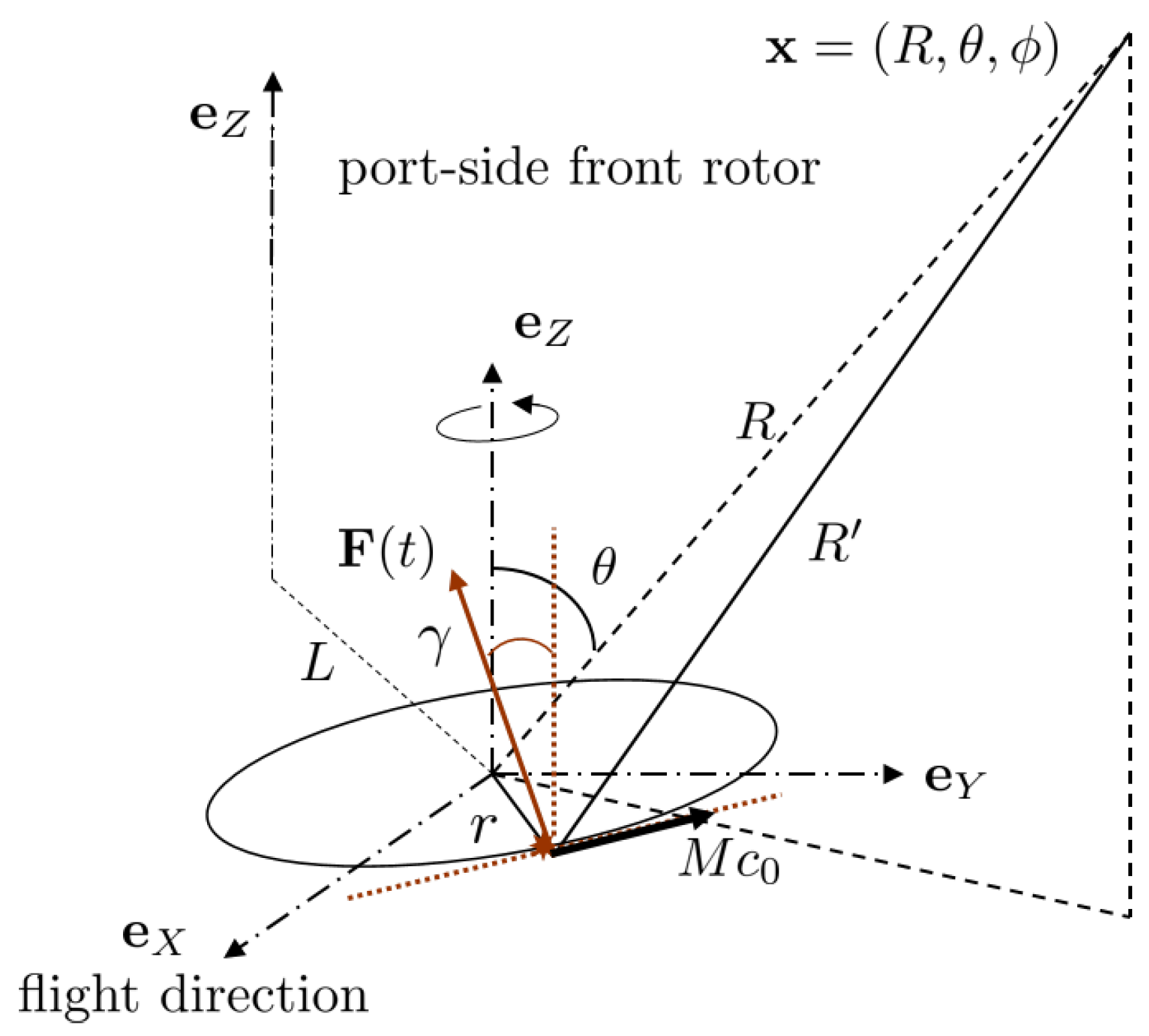
The tonal noise from subsonic open rotors is usually expressed in the frequency domain by the complex-valued sound-pressure amplitude at the harmonic of the angular BPF produced by a blade element of radius r at an arbitrary observation point . Introducing the wavenumber , an expression for this quantity valid everywhere in space reads [22]
with
stands for the exact distance of the element to the observer (see Figure 2). The factors are the complex-valued coefficients of the Fourier series of the periodic force on the blade element acting as an equivalent rotating acoustic dipole. They are called blade-loading harmonics (BLH). is the angle of the sectional dipole/force with respect to a parallel to the axis, or equivalently the blade angle at radius r with respect to the rotational plane. The convention is used for monochromatic waves. A single term of the sum defines a free-field radiation mode. Each mode of order n for a given radius r can be equivalently reproduced by a continuous circular distribution of stationary and phased dipoles at the same radius, provided that:
- -
- the angle of the dipoles is the same value as for the actual fluctuating lift;
- -
- the angular frequency of the stationary dipoles is ;
- -
- the dipole strength at the azimuth along the circle is defined as .
Figure 2.
Source and observer coordinates in the individual reference frame of a rotor. Similar coordinates are defined for other rotors, with both possible directions of rotation.
Figure 2.
Source and observer coordinates in the individual reference frame of a rotor. Similar coordinates are defined for other rotors, with both possible directions of rotation.

Once the circle is discretized for practical implementation and all BLH determined, the radiated sound field is obtained at any point. This mathematical identity is required when studying the scattering by surrounding surfaces, for instance [22,23]. It is used in the present work instead of Equation (1) to compute the free field at arbitrary finite distance, for a better physical insight into the combined radiated fields of a pair of rotors. Anyway, the direct implementation of Equation (1) would also require a numerical treatment of the factors.
3.2. Far-Field Formulation
The acoustic and geometrical far-field condition is fulfilled as soon as the distance of the observer is large when compared to both the characteristic wavelengths of the radiated sound and the diameter of the rotors, or in the present case the typical extent of the quadrotor. The aforementioned expression, Equation (1), is simplified as (for details of the formalism, see also references [13,14])
The radiation efficiency of each mode is emphasized by the Bessel function acting as a weighting factor on the BLH. It is worth noting that if denotes the tangential, kinematic Mach number. The mean value of the sectional blade force is referred to as the steady loading, to be distinguished from all other BLH that result from the operation of the blades through a steady-state but azimuthally distorted mean flow. It must be stressed again that is intrinsic to the blade design. It is the only contributor to the thrust whereas all other coefficient are produced as a result of the distortions and have no direct effect on the aerodynamic performances. In that sense there is no obvious relationship between aerodynamic efficiency and tonal noise in the general case. The question of whether or not the mean force actually contributes to the sound is a key issue. Indeed if it is so, noise reduction can be achieved only through an optimization procedure including the constraint of constant thrust. In contrast, if the noise is attributed to higher-order BLH, sound reduction can be achieved by reducing the distortions as far as possible.
The far-field pressure attributed to steady-loading noise only reduces to the expression
in which the product is directly related to the thrust provided that an additional on-axis projection is considered.
In Equations (1)–(3) the factors refer to sectional integrated forces acting as equivalent point dipoles. This makes sense as long as the chord lengths are acoustically compact, namely much smaller than the wavelengths of interest. This condition is fulfilled for most small-size drone propeller blade sections and taken for granted in the present work.
3.3. Steady-Loading Noise and Forward-Flight Induced Unsteady-Loading Noise
Horizontal flight of a drone at small, negative pitch angle is addressed in this section as responsible for the onset of BLH and for the associated sound generation. Its effect when compared to hover is to involve a non-zero lateral fluid motion in the plane of rotation combined with an axial fluid motion normal to this plane. In absence of accurate prediction of the lift variations on a blade section, a crude estimate is provided by assuming a uniform oblique fluid motion through the rotor disk, with the angle as shown in Figure 1b and the velocity . The latter is equal to the advancing speed and of opposite direction.
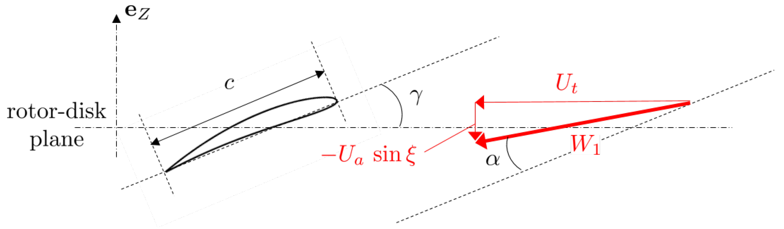
The blade cross-section of radius r is assumed a flat-plate of chord c inclined by the angle with respect to the plane of rotation (rotor disk), parallel to the chord line of the true cross-section profile, as shown in Figure 3. If the flight is assumed along the positive coordinate X ( axis) for a counterclockwise rotating rotor, and if the considered blade element is on this axis at the origin of time, the instantaneous oncoming tangential and axial flow speeds on the cross-section are and , respectively. This leads to expressions for the relative speed at rotor inlet and the associated angle of attack as
noting that the relative spanwise velocity component does not enter the problem.
A cruder analysis assuming a negligible pitch angle would lead to and , providing a first estimate of the fluctuations when the actual pitch angle is unknown. At very low frequencies, the lift variations induced on the blade section can be assessed from a quasi-steady approximation and from the relation between angle of attack and lift coefficient . Based on the theoretical value of Cauchy’s potential theory [24] and assimilating the airfoil to a flat plate, the instantaneous sectional lift simply reads
where c and ℓ are the chord and span of the considered blade segment, and is the density of air. Partly because the advancing ratio is small in practice, the time variations of the lift are close to sinusoidal. This is confirmed by deriving the differential
with
As a result, the onset of the dominant BLH orders is expected, with weaker amplitudes at orders . To check that point, estimates of the coefficients of the Fourier series of , not shown for conciseness, have been calculated from the definition
The mean value associated with steady-loading noise was found typically between 7 and 10 times higher than the BLH amplitudes , whereas higher harmonics were negligible. This crude approximation probably overestimates the relative contribution of steady-loading noise because it ignores the mean-flow gradients, in particular the induced axial flow in the vicinity of the rotor disc. Yet it provides an easy way of comparing the orders of magnitude of steady-loading and unsteady-loading noise.
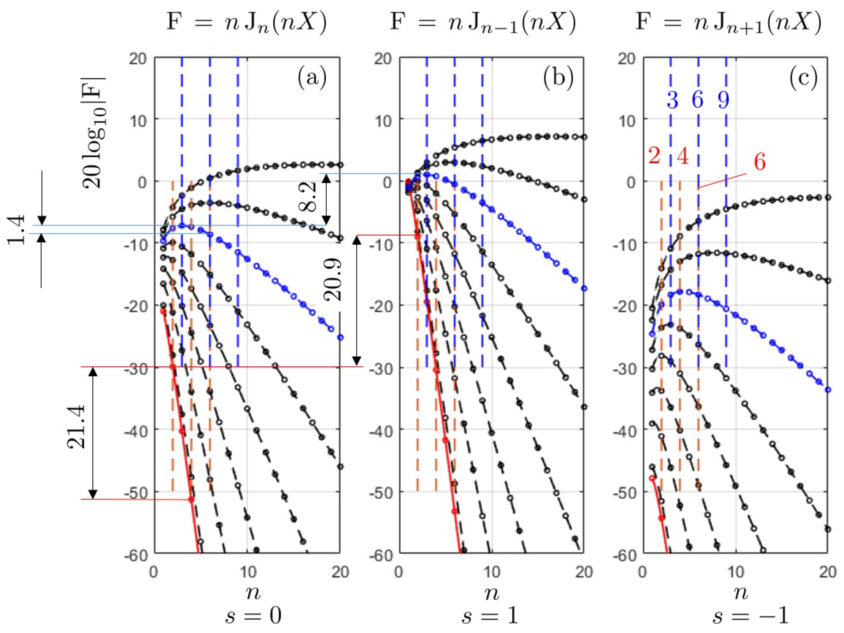
Equation (2) states that steady-loading noise is associated with the radiation-efficiency factor , with and , plotted in Figure 4a as a function of n in equivalent decibels. The factor is an increasing function of X. It is clear that this noise is poorly radiating at low blade-tip Mach numbers for quite large numbers of blades. Yet it becomes significant at higher Mach numbers and/or for small blade numbers, especially if flow distortions are small. As explained above, operation with non-zero lateral flow primarily generates the blade-loading harmonics of orders that trigger the Bessel functions as efficiency factors. These two are also plotted in Figure 4b,c to illustrate the discussion. is to multiply by the steady force on the considered blade segment, whereas the other two are to multiply by the BLH and , both having the same order of magnitude. The first outcome from the figure is that the factor can be neglected, whereas the factor must be considered because it exceeds that of the steady loading, especially at low Mach numbers at the BPF. The drone D1 addressed by Misiorowski et al. [18] corresponds to the indicative value reported as the red data in Figure 4. In this case, the weighting factor of the BLH is 20.9 dB higher than that of the steady load at the BPF. As a result, unsteady-loading noise is expected to exceed steady-loading noise at that frequency as soon as the lift variations reach about 16% of the steady lift. Strictly speaking, the steady-loading possibly radiates a noticeable sound at the blade-tip Mach number of 0.18 and for a two-bladed rotor. This is emphasized by the red dots in Figure 4a. However, the rate of decrease is so fast that the radiation efficiency at 2PBF is already 21.4 dB lower than at the BPF. This suggests that, in practice, steady-loading noise is probably overwhelmed by unsteady-loading noise from the second tone to higher harmonics, even with quite moderate distortions.
For comparison, different parameters corresponding to the quadrotor vehicle analyzed with flow computations by Yoon et al. [19] can also be assessed from the same Bessel-function plots. The blade number in the reference is and the blade-tip Mach number about 0.7. Only values of n that are multiples of 3 and the three curves for are selected in this case. They are shown in blue in the figure. Now the rate of decrease of the curves is much slower. The relatively large values of the function make steady-loading noise expected as a very significant contribution, for several BPF harmonics. Typically the decrease is only of 1.4 dB between the BPF and 2BPF, and about 7 dB between the BPF and 4BPF. Furthermore the weighting factor acting on the BLH of order is 8.2 dB higher than the factor . This stresses that for the same rate of unsteady loading the higher speed corresponds to a smaller difference of radiation efficiency between steady-loading noise and unsteady-loading noise.
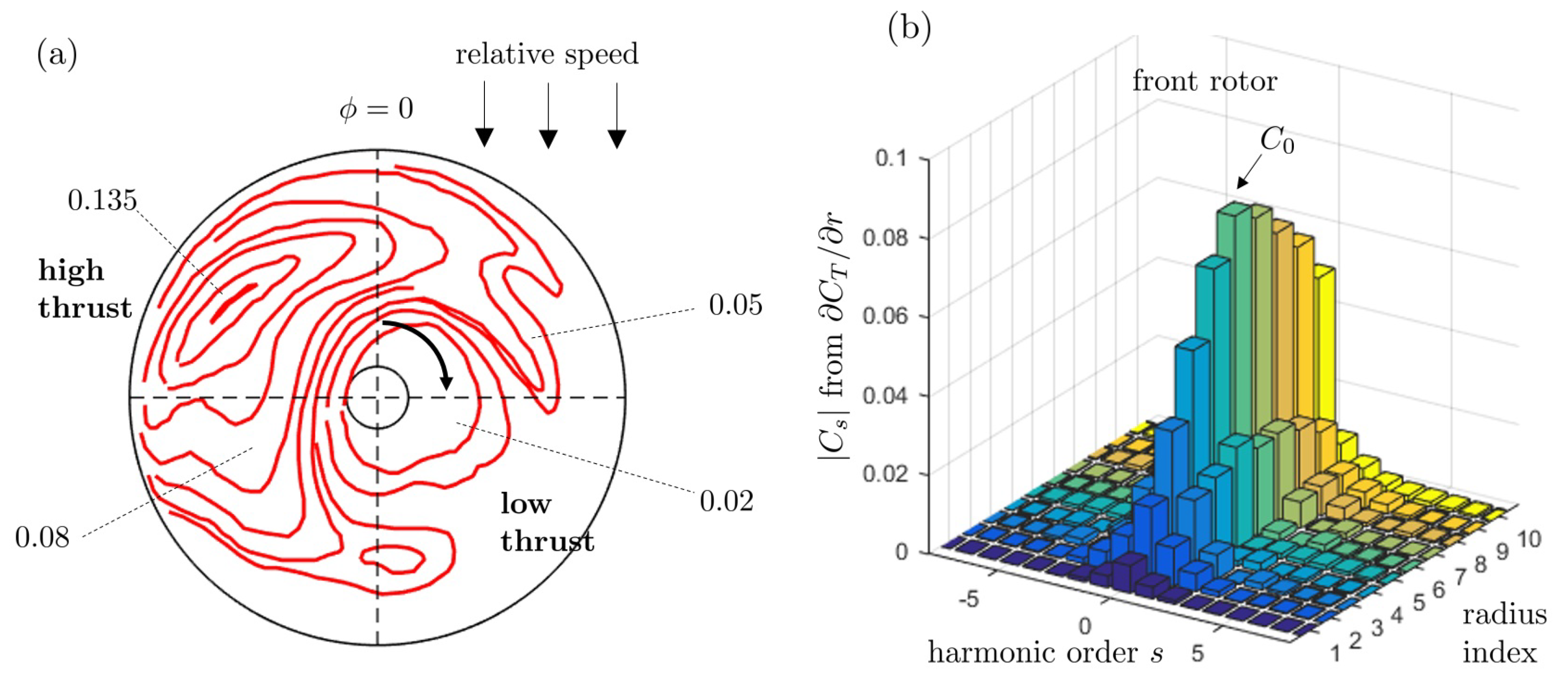
In fact, the true forward flight of a quadrotor produces more complex flow and lift fluctuations, with different BLH amplitudes and orders. This is why attention is paid now to computed flow results on a real drone configuration, and the way they can be used for more accurate sound predictions. The quadrotor investigated by Misiorowski et al. [18] is selected as an example because all required parameters can be found in the reference. The configuration, approximately defined as D1 in Table 1 and shown in Figure 1b, includes the full quadrotor but neither the struts nor the main body of the drone. Therefore the flow blockage and the associated distortions are ignored, which means that only unsteady loads caused by the oblique relative flow are captured. Results from an incompressible Detached-Eddy Simulation were obtained for an advancing flight speed of 10 m/s and a pitch angle of . Iso-contours of the sectional thrust coefficient (per unit span) in the rotor plane as computed in the reference are roughly reproduced in Figure 5a, for the starboard front rotor only. Though a similar analysis could be performed for the rear rotor, it is not essential for the present purpose. Indeed the test is essentially aimed at ranking steady-loading noise and unsteady-loading noise for a rotor in side-flow, on the one hand, and both rear and front rotors have similar qualitative flow features, on the other hand [18]. The view is from above and the rotor is spinning clockwise. The symmetric-image distribution would hold for the portside rotor spinning counterclockwise. The indicative values provided in the figure point high-thrust and low-thrust areas over the rotor disk, corresponding to the advancing and retreating blades, respectively. This is responsible for substantial lift variations on the blades and associated unsteady-loading noise. Indeed, angular variations on the disk correspond to time variations on the blades. Circular cuts of the isocountour-map for ten evenly spaced radii , , have been considered to compute the Fourier coefficients of the sectional lift, thus the BLH, according to the definition
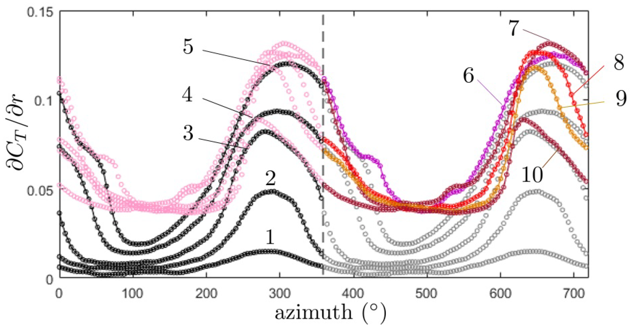
In this operation the angle is followed in the clockwise direction to be in accordance with the time correspondance. The discrete spectrum of the coefficients is displayed as a bar-graph in Figure 5b. corresponds to the averaged thrust of each blade segment, thus the source of the steady-loading noise. The bar-graph evidences thrust harmonics of orders ± 1 of about 20% to 30% of the mean thrust, which makes unsteady-loading noise an efficient contribution. This is substantially more than the aforementioned rough estimates based on the quasi-steady approximation. Therefore, the latter could be used to infer the minimum level of BLH expected in forward flight, in absence of more accurate information about the flow. Anyway, the results confirm the recognition of the modes ± 1 as the typical signature of forward flight. Two periods of the unwrapped angular profiles of the sectional lift at the ten extraction radii are plotted in Figure 6 for completeness. The profiles of the inner area (cuts 1 to 5) are plotted in black and gray; they exhibit a monotonic increase. The profiles of the outer area (cuts 6 to 10) are plotted in pink and colors; they have a substantial plateau of nearly equal minimum values. The maximum lift is found at the cuts 6 and 7. These profiles depart substantially from the quasi-sinusoidal shape expected from the simple analysis based on Equation (6). This is mainly attributed to the aerodynamic coupling between the four rotors and to the detailed features of the induced axial flows, ignored in the analytical model but reproduced in the numerical simulation.
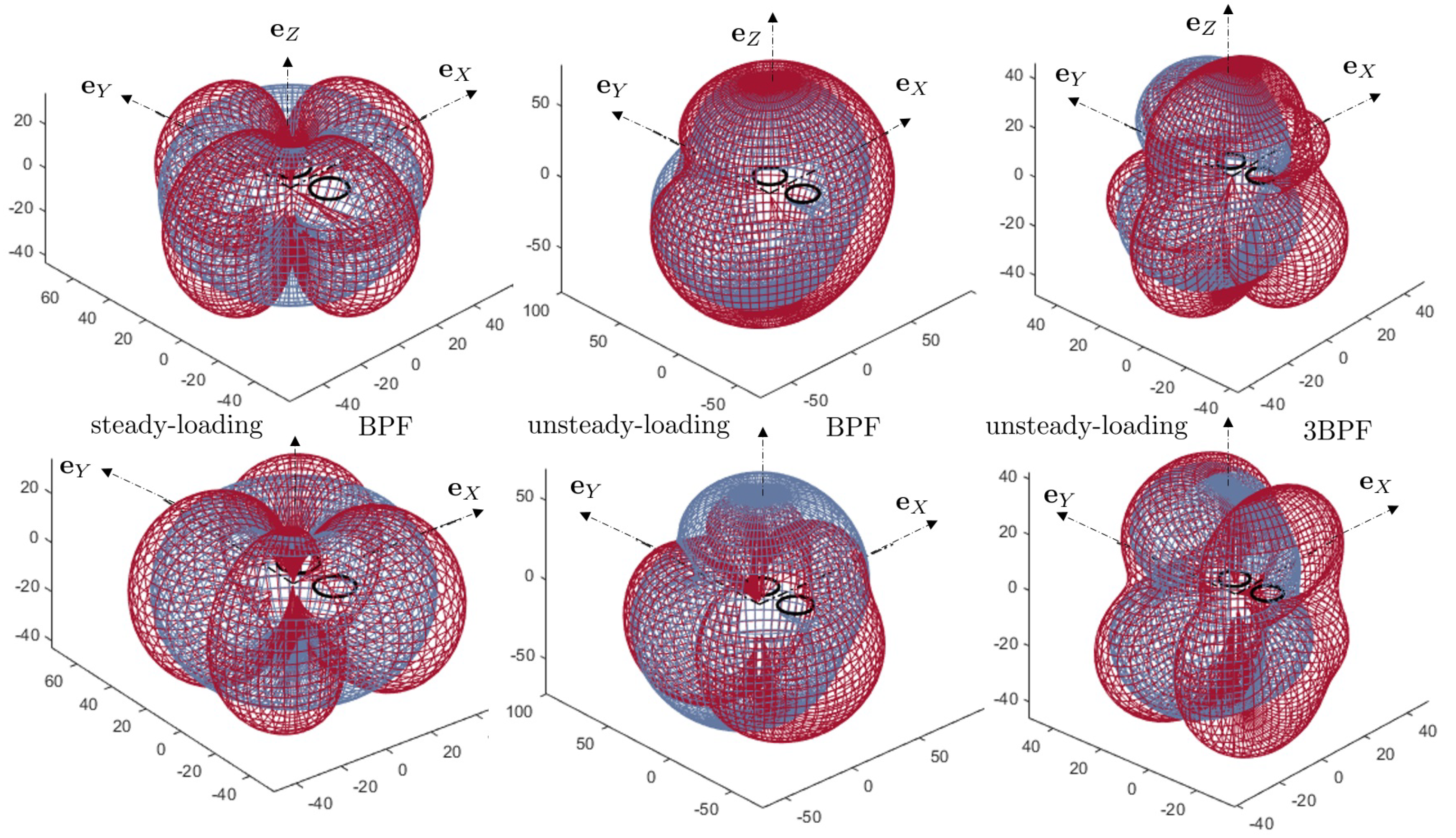
Typical sound predictions made with the present analytical model are reported in Figure 7 in terms of three-dimensional directivity patterns. They are based on a source-mode expansion at the ten aforementioned radii, fed with the complex-valued blade-loading harmonics associated with the bar-graph in Figure 5b. The radius of the observation sphere is 10 , with origin at the quadrotor center-point. Therefore, the observer is in the acoustic far field, in the sense that the distance multiplied by is larger than the wavelength at the BPF, around 150 Hz, but not in the geometric far-field with respect to the general dimensions of the quadrotor. Yet, the basic directivity lobes are already well structured. All radii are taken into account and only the pair of contrarotating front rotors is considered. Indeed, the aft rotors radiate at different frequencies because of their different rotational speed. The test is primarily aimed at comparing the relative amplitudes of the acoustic signatures of the steady loading on the blades and of the lift fluctuations due to forward motion with negative pitch angle. Furthermore, both rotors are synchronized in the test with a zero phase shift (upper plots) and with a phase shift of half a blade passage (lower plots). In the first case, both rotor configurations are symmetric images of each other with respect to the vertical mid-plane of the quadrotor, as well as their isolated acoustic fields. In the second case, any blade-tip passage of one rotor at the minimum distance of both tip circles takes place between two passages of the other rotor. The directivity diagrams are plotted as interpenetrating meshed surfaces for a better illustration of the differences between the sound field of a single rotor and that of the pair of rotors. They exhibit main lobes separated by extinction angles.
The directivity at the BPF is shown for the steady-loading noise only in the left plots and for the total noise in the middle plots. Obviously, the former is much lower than the latter, except at angles approaching . Steady-loading noise therefore contributes to the horizontal radiation for normal operating conditions. It could contribute, for instance, to the sound received on building walls during urban operations. In other directions, the sound is essentially attributed to unsteady loads on the blades. The amplitude of steady-loading noise decreases dramatically at higher harmonics. This is why only the total-noise directivity, almost equal to that of the unsteady-loading noise, is shown for the harmonic 3BPF in the right plots; it exhibits a larger number of lobes as an effect of higher non-compactness. A general feature of the tonal noise of a single rotor in arbitrary distortion is the dominant radiation around the rotational axis, associated with the symmetric mode fed with the BLH . Unlike steady-loading noise, unsteady-loading noise preferentially radiates vertically. The synchronization with zero phasing reinforces the sound around the vertical plane with respect to what the radiation of a single rotor would be. In contrast, the half-blade passage phasing leads to the cancellation of the sound in the vertical plane aligned with the forward flight direction for odd harmonic orders, as expected, at the price of a more efficient radiation at oblique angles. The outcomes of those sample results are twofold. Firstly, thrust and forward-flight associated contributions to the total sound have different radiating properties. Secondly, the former is significant only at lowest frequencies. By virtue of the weaker loudness at low frequencies in terms of the A-weighted decibels, unsteady-loading noise clearly dominates. Yet, in view of the test case reported in Figure 7, and apart from the different directivity patterns, steady-loading noise at the BPF is only about 10 dB below unsteady-loading noise. This suggests that it could dominate in hover, at least if no other mean-flow distortion is considered. However, such distortions can also be generated by supporting struts, as discussed in Section 3.4.
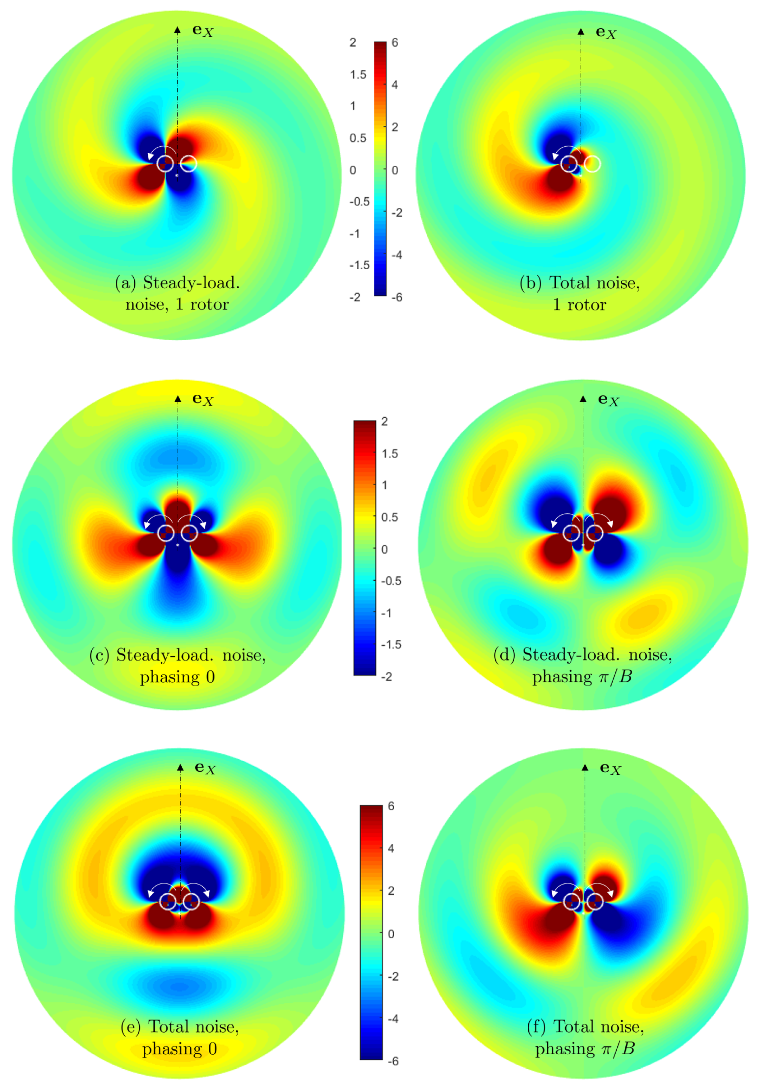
For a complementary view of basic interference features of the sound field, maps of the instantaneous acoustic pressure in the rotor plane and in the neighborhood of the pair of rotors are shown in Figure 8. Over-pressures and under-pressures are shown in red and blue, respectively, green corresponding to the undisturbed static pressure. Arbitrary but comparable color scales are used, in the range for steady-loading noise and in the range for the total noise. Only the BPF is illustrated, for conciseness. The first two sub-plots illustrate the radiation of the port-side rotor only (the rotors are featured as white circles) for the steady-loading noise in Figure 8a and the total noise in Figure 8b. The expected mode 2 , with clearly formed spiral branches, is recognized in the first case. A mode complex pattern is found in the second case, with a dominant mode fed by the BLH of order . Steady-loading noise maps of the pair of rotors are shown for zero phasing and half-blade passage phasing in Figure 8c,d, respectively. In the case of zero phasing, the rotors are perfect symmetric images of each other, as well as the associated wavefront patterns. Therefore, the map is again symmetric with respect to the axis. In the case of half-blade passage phasing, the sound pressure is zero at any time along the axis, with out-of-phase pressure fluctuations on both sides of the axis. In both cases, the four lobes seen on the directivity diagrams in Figure 7 (left side) are already formed at quite short distances from the center of the quadrotor, with local distortions in the very vicinity of the rotors. Finally, similar maps are plotted for the total noise in Figure 8e,f, with, again, symmetry in the case of zero phasing, and cancellation in the vertical plane aligned with the flight direction in the case of half-blade passage phasing. Qualitatively, in view of the color scales, the amplitude of the total noise is about three times higher than that of the steady-loading noise.
3.4. Generic Potential-Interaction Noise Model
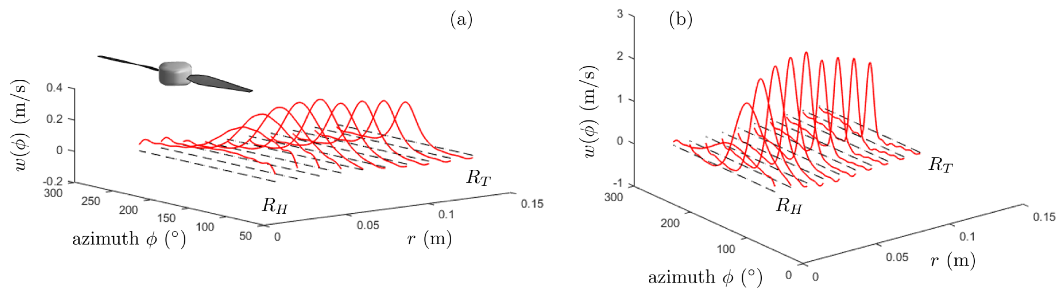
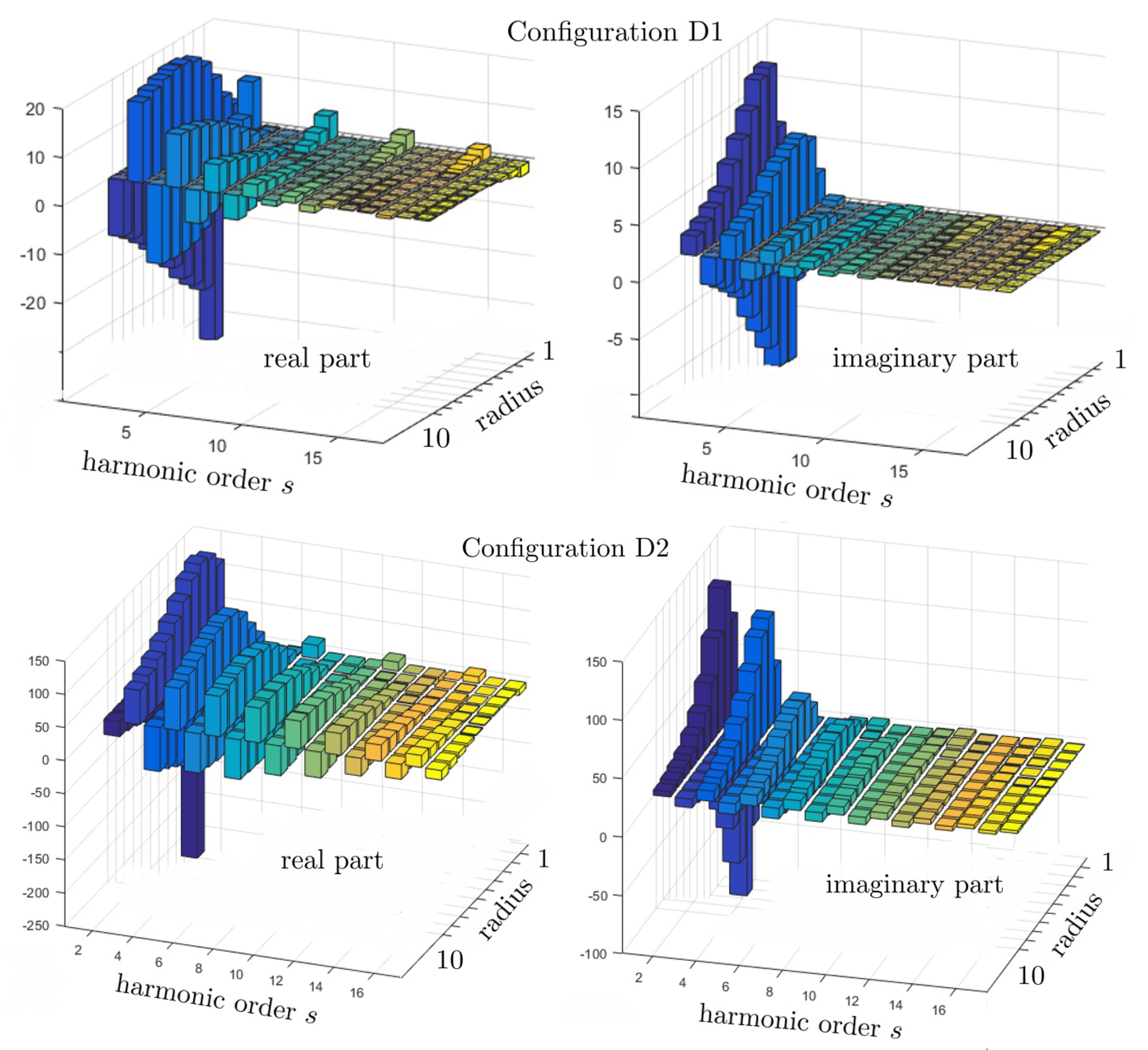
A single rotor-strut system of a drone is similar to the technology of the tail rotor of a helicopter. Indeed, the transmission shaft radially positionned just downstream of the rotor for the latter plays the same obstruction role as the strut for the former. A strong tonal noise is generated in this case, for which an analytical model has been proposed by Roger et al. [23,25], as follows. The distorted flow around any shaft cross-section is assimilated to the two-dimensional potential flow around a circle [26]. Exact analytical expressions are deduced for the Fourier coefficients of the upwash (velocity fluctuation normal to the chord) experienced by the blades when crossing the distortion periodically, by complex-residue calculations. The expressions, not reproduced here for conciseness, have been implemented for a single rotor in both cases D1 and D2, assuming that the relative flow downstream of the blades is aligned with the local chord line, for simplicity. This defines the angle of the flow relative to the strut, of speed , accordingly. The results for the angular upwash profiles at the 10 radii previously defined are reported in Figure 9 and those for the associated Fourier coefficients in Figure 10. Repeated predictions previously performed with the exact analytical solution confirmed the relevance of an empirical best fit proposed by Roger and Kucukcoskun [23]. According to this fit, the complex-valued distortion harmonics are approximated as
where are adjustable parameters, functions of the configuration. The empirical fit allows estimating the BLH in any architecture for which a propeller operates in close vicinity of a radial strut or arm once the latter is assimilated to an equivalent cylinder of circular cross-section. In the present application, the simplified expression, Equation (8), has been found to deviate from the exact results for very attenuated distortion profiles, and to be quite relevant for pronounced ones. It agrees qualitatively with the alternately positive and negative values illustrated in Figure 10, especially for the configuration D2. Therefore, it could become the basis of a simplified formulation for extensive impact studies, provided that the coefficients are tuned beforehand on some typical test cases. Such an investigation is beyond the scope of the present work.
In configuration D1, the strut is quite thin and far away below the rotor disk, leading to a priori negligible potential distortion at the rotor position. Indeed, the equivalent radius a is of about and the interaction distance of about . The corresponding weak upwash is illustrated in Figure 9a. In contrast, configuration D2 features quite thick struts at shorter interaction distance, which generate a strong potential distortion. The corresponding upwash plotted in Figure 9b is about 10 times larger. The azimuthally averaged value of the upwash contributing to the thrust-associated coefficient of Section 3.3 is not considered in the present prediction only aimed at assessing unsteady-loading noise. Furthermore, the decrease of the amplitude with the harmonic order s is slightly faster in configuration D1.
In view of the chordwise compactness of the blades (chord length smaller than the acoustic wavelengths) and of the moderate Mach numbers (about 0.2), the sectional BLH can be approximately inferred from Sears’ theory, leading to the expression , where stands for the classical Sears’ function [14] and c for the chord length of the blades at the radius r.
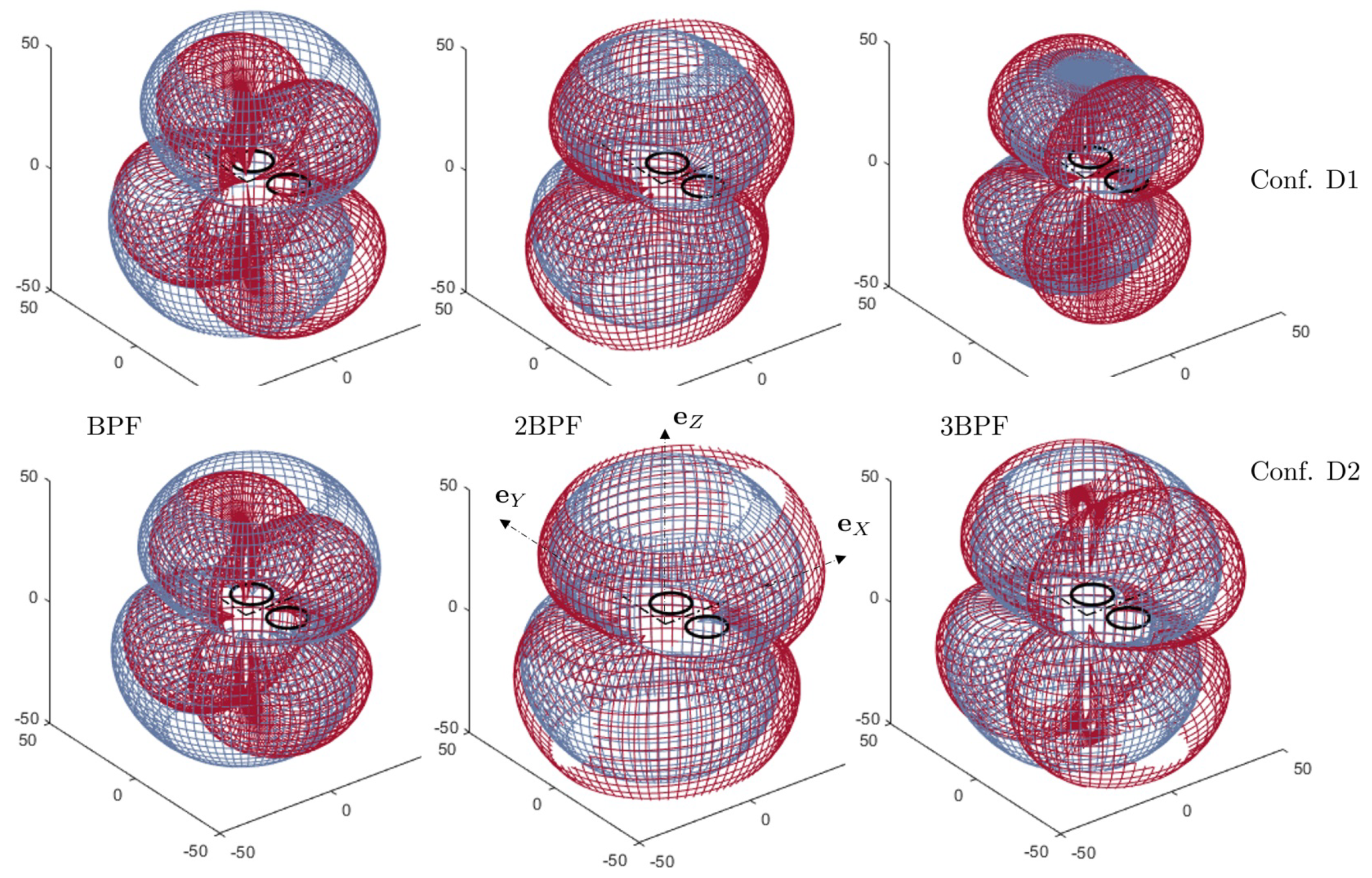
Typical directivity patterns of potential-interaction noise as deduced from the upwash profiles in Figure 9 are shown in Figure 11, for configurations D1 and D2 at the same rotational speed of 4058 rpm. Both differ in terms of amplitudes. Unexpectedly, the sound at the BPF is of similar level in both cases, in spite of the much closer obstruction caused by the struts in configuration D2. In fact, the larger size in configuration D1 balances the weaker distortion. The difference in radiated noise is more pronounced at higher BPF harmonics, especially at 3BPF for which configuration D2 is much louder, as expected from its general design. A shorter rotor-strut distance induces stronger and more impulsive lift variations on the blades, thus a lower decrease of the BLH envelope, which also makes more sound expected at higher BPF harmonics.
Because both the potential distortion and the forward-flight effect generate BLH of all orders, they have similar radiating features. For a single rotor, the sound is again mainly radiated vertically, with a minimum around the rotational plane. Synchronization with zero phasing reinforces this trend, whereas half-blade passage phasing forces radiation at oblique directions and leads to sound cancellation in the vertical plane aligned with the flight direction.
4. Conclusions
The simple results obtained in this work with a set of realistic parameters indicate that the tonal noise from small-size quadrotors in operation is essentially generated by periodic blade forces due to forward flight and/or installation effects. In particular, they raise the possible occurrence of penalizing potential-interaction noise in case of too close proximity of a rotor with its supporting strut. Steady-loading noise associated with thrust contributes in horizontal directions for normal operating conditions, only at the lowest frequencies. In contrast, unsteady-loading noise radiates preferentially around the vertical axis, except if this radiation is cancelled by virtue of a proper phasing between synchronized rotors. In this case, the dominant radiation is at oblique angles. These properties are key features to pay attention to when assessing noise in urban areas, depending on either the focus is on radiation towards the ground or radiation towards building walls. They suggest that substantial sound reduction could be achieved by optimizing the mounting of the rotors and controlling the flight speed. The proposed analytical models allow testing numerous scenarios in a short time, changing parameters such as rotor-strut distance, blade number, rotational speed and so on, but their need for input data remains a crucial point. For preliminary assessment, potential-interaction noise calculations assimilating a strut to a circular cylinder make sense, provided that an equivalent cross-section diameter is defined from the real geometry. Forward-flight induced noise estimates are also possible assuming the dominance of the BLH of orders with an amplitude of 25–30% of thrust in typical conditions. More accurate predictions require that the velocity disturbances are first determined from unsteady flow simulations. For instance, compressible Lattice–Boltzmann solvers are an attractive alternative from which the flow and the sound are predicted as a whole, but such unsteady computations are still computationally intensive and can only be performed on a small number of configurations.
The present results have been obtained by implementing a source-mode expansion which yields valid results in the entire space. Much faster estimates could be obtained resorting to a far-field approximation. However, the main advantage of the source-mode formalism is that it can also be used to provide inputs to any Green’s function tailored to a scattering body of simple geometry [27], or to any Helmholtz-equation solver. This allows to investigate, for instance, the masking or diffraction of propeller noise by corners of buildings, or its scattering by the main body of a drone, accounting for the true radiating properties of the sources. The approach could enable manufacturers to define low-noise architectures or operational procedures, and planners to estimate the environmental impact of an urban fleet of drones. Finally, an experimental validation could be performed on a database in which parameters such as pitch angle and advancing flight are rigorously controlled. Such a database would require extended tests and could be the matter for future work.
Author Contributions
Conceptualization, M.R. and S.M.; Formal analysis, M.R. and S.M.; Investigation, M.R. and S.M.; Methodology, M.R. and S.M.; Validation, M.R. and S.M.; Writing—review and editing, M.R. and S.M. All authors have read and agreed to the published version of the manuscript.
Funding
This research received no external funding.
Acknowledgments
This work was performed within the framework of the LABEX CeLyA (ANR-10-LABX-0060) of Université de Lyon, within the program Investissements d’Avenir (ANR-11-IDEX-0007) operated by the French National Research Agency (ANR). It was also partly supported by the French-Canadian Associate Laboratory CAC (Centre Acoustique Jacques Cartier).
Conflicts of Interest
The authors declare no conflict of interest.
References
- Papa, U.; Iannace, G.; Core, G.D.; Giordano, G. Sound power level and sound pressure level characterization of a small unmanned aircraft system during flight operations. Noise Vib. Worldw. 2017, 48, 67–74. [Google Scholar] [CrossRef]
- Christian, A.; Cabell, R. Initial Investigation into the Psychoacoustic Properties of Small Unmanned Aerial System Noise. In Proceedings of the 23rd AIAA/CEAS Aeroacoustics Conference, Denver, CO, USA, 5–9 June 2017. AIAA 2017-4051 paper. [Google Scholar]
- Vascik, P.D.; Hansman, R.J. Scaling Constraints for Urban Air Mobility Operations: Air Traffic Control, Ground Infrastructure, and Noise. In Proceedings of the 2018 Aviation Technology, Integration, and Operations Conference, Atlanta, GA, USA, 25–29 June 2018. AIAA 2018-3849 paper. [Google Scholar]
- Nardari, C.; Casalino, D.; Polidoro, F.; Coralic, V.; Brodie, J.; Lew, P. Numerical and Experimental Investigation of Flow Confinement Effects on UAV Rotor Noise. In Proceedings of the 25th AIAA/CEAS Aeroacoustics Conference, Delft, The Netherland, 20–23 May 2019. AIAA 2019-2497 paper. [Google Scholar]
- Casalino, D.; van der Velden, W.C.P.; Romani, G.; Gonzales-Martino, I. Aeroacoustic Analysis of Urban Air Operations using the LB/VLES Method. In Proceedings of the 25th AIAA/CEAS Aeroacoustics Conference, Delft, The Netherland, 20–23 May 2019. AIAA 2019-2662 paper. [Google Scholar]
- Intaratep, N.; Alexander, W.N.; Devenport, W.J.; Grace, S.M. Experimental Study of Quadcopter Acoustics and Performance at Static Thrust Conditions. In Proceedings of the 22nd AIAA/CEAS Aeroacoustics Conference, Lyon, France, 30 May–1 June 2016. AIAA 2016-2873 paper. [Google Scholar]
- Yauwenas, Y.; Fisher, J.; Moreau, D.; Doolan, C. The effect of inflow disturbance on drone propeller noise. In Proceedings of the 25th AIAA/CEAS Aeroacoustics Conference, Delft, The Netherland, 20–23 May 2019. AIAA 2019-2663 paper. [Google Scholar]
- Serré, R.; Gourdain, N.; Jardin, T.; Jacob, M.; Moschetta, J. Towards silent micro-air vehicles: Optimization of a low Reynolds number rotor in hover. Int. J. Aeroacoustics 2019, 18, 690–710. [Google Scholar] [CrossRef]
- McKay, R.S.; Kingan, M.J. Multirotor Unmanned Aerial System Propeller Noise Caused by Unsteady Blade Motion. In Proceedings of the 25th AIAA/CEAS Aeroacoustics Conference, Delft, The Netherland, 20–23 May 2019. AIAA 2019-2499 paper. [Google Scholar]
- Jiang, H.; Zhou, T.; Fattah, R.; Zhiang, X. Multi-rotor noise scattering by a drone fuselage. In Proceedings of the 25th AIAA/CEAS Aeroacoustics Conference, Delft, The Netherland, 20–23 May 2019. AIAA 2019-2586 paper. [Google Scholar]
- Bian, H.; Fattah, R.; Sun, Y.; Zhang, X. Noise prediction of drones in urban environments. In Proceedings of the 25th AIAA/CEAS Aeroacoustics Conference, Delft, The Netherland, 20–23 May 2019. AIAA 2019-2685 paper. [Google Scholar]
- Ffowcs Williams, J.E.; Hawkings, D.L. Sound Generation by Turbulence and Surfaces in Arbitrary Motion. Phil. Trans. R. Soc. A 1969, A264, 321–342. [Google Scholar]
- Ffowcs-Williams, J.E.; Hawkings, D.L. Theory relating to the noise of rotating machinery. J. Sound Vib. 1969, 10, 10–21. [Google Scholar] [CrossRef]
- Goldstein, M.E. Aeroacoustics; Mc Graw-Hill: New York, NY, USA, 1976. [Google Scholar]
- Lighthill, M.J. The Bakerian Lecture 1961, Sound generated aerodynamically. Proc. R. Soc. A Math. Phys. Eng. Sci. 1962, 267, 147–182. [Google Scholar]
- Dahan, C.; Avezard, L.; Guillien, G.; Malarmey, C.; Chombard, J. Propeller Light Aircraft Noise at Discrete Frequencies. J. Aircr. 1981, 18, 480–486. [Google Scholar] [CrossRef]
- Tinney, C.E.; Sirohi, J. Multirotor Drone Noise at Static Thrust. AIAA J. 2018, 56, 2816–2826. [Google Scholar] [CrossRef]
- Misiorowski, M.; Gandhi, F.; Oberai, A.A. A Computational Study on Rotor Interactional Effects for a Quadcopter in Edgewise Flight. AIAA J. 2019, 57, 5309–5319. [Google Scholar] [CrossRef] [Green Version]
- Yoon, S.; Lee, H.C.; Pulliam, T.H. Computational Analysis of Multi-Rotor Flows. In Proceedings of the 54th AIAA Aerospace Sciences Meeting, San Diego, CA, USA, 4–8 January 2016. AIAA 2016-0812 paper. [Google Scholar]
- Ventura Diaz, P.; Yoon, S. High-Fidelity Computational Aerodynamics of Multi-Rotor Unmanned Aerial Vehicles. In Proceedings of the AIAA SciTech Forum, Kissimmee, FL, USA, 8–12 January 2018. AIAA 2018-1266 paper. [Google Scholar]
- Moreau, S.; Sanjosé, M. Sub-harmonic broadband humps and tip noise in low-speed ring fans. J. Acoust. Soc. Am. 2016, 139, 118–127. [Google Scholar] [CrossRef] [PubMed]
- Roger, M.; Moreau, S. Aeroacoustic Installation Effects in Cooling Fan Systems Part 1: Scattering by Surrounding Surfaces. In Proceedings of the International Symposium on Transport Phenomena and Dynamics of Rotating Machinery, Honolulu, HI, USA, 17–22 February 2008. 2008-20222 paper. [Google Scholar]
- Roger, M.; Kucukcoskun, K. Near-and-Far Field Modeling of Advanced Tail-Rotor Noise Using Source-Mode Expansions. J. Sound Vib. 2019, 453, 328–354. [Google Scholar] [CrossRef]
- Anderson, J.D. Fundamentals of Aerodynamics; McGraw-Hill: New York, NY, USA, 2011. [Google Scholar]
- Roger, M.; Moreau, S.; Guédel, A. Vortex-shedding noise and potential-interaction noise modeling by a reversed sears’ problem. In Proceedings of the 12th AIAA/CEAS Aeroacoustics Conference, Cambridge, MA, USA, 8–10 May 2006. AIAA 2006-2607 paper. [Google Scholar]
- Batchelor, G.K. An Introduction to Fluid Dynamics; Cambridge University Press: Cambridge, UK, 2000. [Google Scholar]
- Roger, M.; Moreau, S.; Kucukcoskun, K. On sound scattering by rigid edges and wedges in a flow, with applications to high-lift device aeroacoustics. J. Sound Vib. 2016, 362, 252–275. [Google Scholar] [CrossRef]
Figure 1.
Generic quadrotor architecture with main geometrical parameters (a) and addressed test cases of hover (struts) and of forward flight (no strut) (b).
Figure 1.
Generic quadrotor architecture with main geometrical parameters (a) and addressed test cases of hover (struts) and of forward flight (no strut) (b).

Figure 3.
Idealized instantaneous velocity triangle for a blade cross-section in forward flight with negative pitch (red) and main definitions.
Figure 3.
Idealized instantaneous velocity triangle for a blade cross-section in forward flight with negative pitch (red) and main definitions.

Figure 4.
Weighting factors on the steady-loading noise (a) and on the low-order blade-loading harmonics of unsteady-loading noise and ((b) and (c), respectively). Values of by steps of 0.1 from 0.2 to 0.9. Value featured in red added as representative of the drone D1 (). Value highlighted in blue as representative of the quadrotor reported by Yoon et al. [19] (). Vertical dashed lines standing for the first three BPF orders .

Figure 5.
(a) Isocontours of the sectional thrust coefficient on a front rotor of the quadrotor D1 in forward flight, from [18]. Typical values given on the plot. (b) Modulus of the associated Fourier coefficients for ten circular cuts.
Figure 5.
(a) Isocontours of the sectional thrust coefficient on a front rotor of the quadrotor D1 in forward flight, from [18]. Typical values given on the plot. (b) Modulus of the associated Fourier coefficients for ten circular cuts.

Figure 6.
Two periods of the unwrapped angular profiles of sectional thrust for the 10 circular cuts in the map of Figure 5a (numbered on the plot). Inner and outer profiles highlighted on the left and right parts by black and colored markers, respectively, for clarity.
Figure 6.
Two periods of the unwrapped angular profiles of sectional thrust for the 10 circular cuts in the map of Figure 5a (numbered on the plot). Inner and outer profiles highlighted on the left and right parts by black and colored markers, respectively, for clarity.

Figure 7.
Three-dimensional directivity patterns of forward-flight noise, at from the quadrotor center. Single rotor (gray-blue) and pair of front rotors (dark red). Flight in the direction . Synchronized rotors with zero phasing (top) and half-blade passage phasing (bottom). Configuration D1, scales in arbitrary decibels.

Figure 8.
Computed instantaneous pressure maps of the steady-loading noise (a–d) and of the total noise (e,f), in the plane of the front rotors of configuration D1, at the BPF. (a,b) Single-rotor signature; (c,e) zero phasing; (d,f) half-blade passage phasing. Rotations indicated by arrows, flight direction along , tip-radius circles drawn in white.

Figure 9.
Azimuthal profiles of the upwash on the blades (normal to the chord) according to the potential-interaction model [25]. Configurations D1 (a) and D2 (b).
Figure 9.
Azimuthal profiles of the upwash on the blades (normal to the chord) according to the potential-interaction model [25]. Configurations D1 (a) and D2 (b).

Figure 10.
Bar-graphs of the upwash Fourier coefficients deduced from Figure 9, normalized by . Exact potential-interaction model [25]. Single two-bladed propeller, configurations D1 (top) and D2 (bottom).

Figure 11.
Three-dimensional directivity patterns of potential-interaction noise at from the quadrotor center. Single rotor (gray-blue) and pair of front rotors (dark red). Flight in the direction . Half-blade passage phasing synchronization. Configurations D1 (upper plots) and D2 (lower plots), same scales in arbitrary decibels.


Table 1.
Main parameters of the quadrotor configurations used as test cases. Drone D1 used in both Section 3.3 and Section 3.4, drone D2 used only in Section 3.4.
Table 1.
Main parameters of the quadrotor configurations used as test cases. Drone D1 used in both Section 3.3 and Section 3.4, drone D2 used only in Section 3.4.
| L (m) | D (m) | (m) | (m) | d (m) | a (m) | (rpm) | |
|---|---|---|---|---|---|---|---|
| drone D1 | 0.229 | 0.323 | 0.019 | 0.152 | 0.076 | 0.014 | 4058 |
| drone D2 | 0.177 | 0.250 | 0.01 | 0.083 | 0.025 | 0.012 | 4058 |
© 2020 by the authors. Licensee MDPI, Basel, Switzerland. This article is an open access article distributed under the terms and conditions of the Creative Commons Attribution (CC BY) license (http://creativecommons.org/licenses/by/4.0/).
Share and Cite
MDPI and ACS Style
Roger, M.; Moreau, S. Tonal-Noise Assessment of Quadrotor-Type UAV Using Source-Mode Expansions. Acoustics 2020, 2, 674-690. https://doi.org/10.3390/acoustics2030036
AMA Style
Roger M, Moreau S. Tonal-Noise Assessment of Quadrotor-Type UAV Using Source-Mode Expansions. Acoustics. 2020; 2(3):674-690. https://doi.org/10.3390/acoustics2030036
Chicago/Turabian StyleRoger, Michel, and Stéphane Moreau. 2020. "Tonal-Noise Assessment of Quadrotor-Type UAV Using Source-Mode Expansions" Acoustics 2, no. 3: 674-690. https://doi.org/10.3390/acoustics2030036