Article

Multiscale Study of Interactions Between Corrosion Products Layer Formed on Heritage Cu Objects and Organic Protection Treatments

by
Maëva L’héronde
1,2,
Muriel Bouttemy
2,
Florence Mercier-Bion
1,*,
Delphine Neff
1,
Emilande Apchain
1,
Arnaud Etcheberry
2 and
Philippe Dillmann
1
1
LAPA-IRAMAT, NIMBE, CEA, CNRS, Université Paris-Saclay, CEA Saclay, 91191 Gif-sur-Yvette, France
2
Institut Lavoisier de Versailles (ILV), Université de Versailles Saint-Quentin-en-Yvelines, Université Paris-Saclay, CNRS, 45 avenue des États-Unis, 78035 Versailles, France
*
Author to whom correspondence should be addressed.
Heritage 2019, 2(3), 2640-2651; https://doi.org/10.3390/heritage2030162
Submission received: 30 July 2019 / Revised: 27 August 2019 / Accepted: 28 August 2019 / Published: 16 September 2019
(This article belongs to the Special Issue Cultural Heritage—Science, Materials and Technologies)

Abstract

:
In the framework of the protection of copper objects exposed to atmospheric corrosion, different solutions are envisaged, among them carboxylate treatments (HC10). In this study, an analytical approach based on complementary techniques from micrometer to nanometer scale (μRS, SEM-EDS, SAM) is used to describe the properties of the corrosion products layer (CPL) and determine the penetration depth of the HC10 protection treatment inside the CPL of copper samples issued from the roof of the Saint Martin church in Metz. The CPL consists in a thick brochantite layer (20 to 50 μm), mainly composed of Cu4SO4(OH)6, on top of a thinner (1 to 5 μm thick) cuprite layer, Cu2O, acting as a natural corrosion barrier on the metal. Application of the organic treatment is implemented by immersing the corroded samples in HC10 solution, consistent with future requirements for large scale applications. Even for short-term duration (one minute), the HC10 treatment penetrates to the cuprite/brochantite interface, but Cu(C10)2 precipitate is only detected locally, whereas for a longer immersion of thirty minutes, it is present in higher proportions in the whole brochantite layer, filling the pores, up to the cuprite/brochantite interface. Cu(C10)2 acts as a second inner barrier and prevents liquid infiltration.

Graphical Abstract

1. Introduction

In the outdoor environment, copper cultural heritage objects undergo alterations caused by water and atmospheric pollution. The atmospheric corrosion of these objects leads to their physical and aesthetic modifications by the interaction of the environment with the patina. This superficial corrosion layer is finally an integral part of the object and has to be preserved. To protect the cultural heritage objects from the atmospheric corrosion, different types of treatments are used by the restorers: varnishes, waxes, and corrosion inhibitors [1]. The advantage of varnishes and waxes is that they do not significantly modify the surface appearance but are efficient. Indeed, such treatments create a physical barrier on the surface and thus prevent interactions between the atmosphere and the objects. However, varnishes have the disadvantage of being difficult to reprocess and waxes of having a bad hold in time. Concerning corrosion inhibitors, including benzotriazole (BTA) which is currently used for restoration, several studies have reported a possible toxicity of this type of inhibitor for the environment and, as well, for the restorers [2,3,4].
The search for new corrosion inhibiting treatments, non-toxic, is a major issue in the field of heritage. So, other types of corrosion inhibitors have emerged since several decades: Carboxylates, derivatives of fatty acids extracted from vegetable oils [5,6,7,8,9,10,11,12,13]. We have chosen to develop a protection treatment procedure using a carboxylate organic compound. The chemical formula of the carboxylic acids is CH3-(CH2)n-2-COOH, generally denoted by HCn, where n corresponds to the number of carbon atoms composing the aliphatic chain, n being equal to 10 in the present study (HC10). The inhibitory property of carboxylate solutions results from the reaction between the copper ions and the carboxylates which leads to the precipitation of metal carboxylates Cu(C10)2 (metal soaps) on the surface of the corrosion products layer (CPL). These metallic soaps act as surfactants due to the carboxylate part of the molecule providing a hydrophilic character, but have also hydrophobic properties, in relation with the aliphatic chain. Due to its hydrophobic character, this molecule may form a layer on the surface of the metal, and in this case avoid the penetration of water to the interface with the metal and slows down the corrosion of the copper object. To our knowledge, carboxylate treatments have been mainly studied on non-patinated copper objects. Such treatments have yet proven their efficiency in industry and non-corroded heritage objects (iron and copper) with the evidence of corrosion limitation for different metals (zinc, lead and iron) [5,6,7,8,9,10,11,12].
In recent studies [13], we have succeeded in implementing this type of treatment on corroded samples issued from heritage objects and have highlighted its effectiveness. Present work focuses on the determination of the optimal conditions of use of the carboxylate treatment (HC10) and particularly, the immersion time as a key factor. The fine determination of the depth penetration of the HC10 solution in the CPL and its interactions with the corrosion products are major issues. Indeed, the literature concerning the treatment of corroded metals by HC10 is not extensive, and especially, the CPL/HC10 layer interaction mechanism remains an open question. To bring new insights on this problematic, we have developed an analytical approach based on the complementary use of different techniques, with spatial resolution ranging from micrometer to nanometer scale: µRaman Spectroscopy (µRS), Scanning Electron Microscopy (SEM) with Energy Dispersive Spectroscopy (EDS) and Scanning Auger Microscopy (SAM). Such analytical strategy, combining more usual (OM, SEM-EDS, µRS, XRD…) and advanced characterization techniques (XPS, SIMS, PIXE, RBS…) using either conventional laboratory or particle accelerator sources has already been employed on Cu based and metallic artefacts to study the corrosion phenomena in various conditions such as sea water immersion, soils burying or air ageing [14,15,16] enabling to bring an accurate description of the corrosion layers and crucial information about the corrosion mechanism. This knowledge represents an undeniable added value to guide preservation and storage actions. This multi-technique approach is also a good practice to ensure the reliability of the chemical information obtained. Different studies have shown for example the instability of copper compounds under X-Ray irradiation [17] and so evidenced the difficulty to implement XPS without modifying the initial information about the oxidation degree. This specific question will be treated in more details in a future paper.
In the present study, analyses were realized on copper samples issued from the roof of the Saint Martin church in Metz, immersed during one and thirty min in the HC10 solution. We have decided to employ chemical analyses only for the determination of the spatial distribution of elements considering tracking elements representative of the different compounds present Cu, O, S for the CPL and C for the Cu(C10)2. In particular, SAM implementation, essential in our approach to reach the sub-micron scale, was a real challenge on treated samples containing organic compounds not really prone to be analyzed by a focused electron beam technique and in UHV. However, thanks to a tailored sample preparation protocol, significant information concerning the Cu(C10)2 formation could be evidenced bringing a better insight on its action against corrosion. Thanks to this multi-technique approach, CPL composition and structuration could be accurately determined, HC10 penetration studied and its inhibiting capabilities evaluated from 1 to 30 min. This represents an important knowledge for the development and optimization of future preservation strategies.

2. Materials and Methods
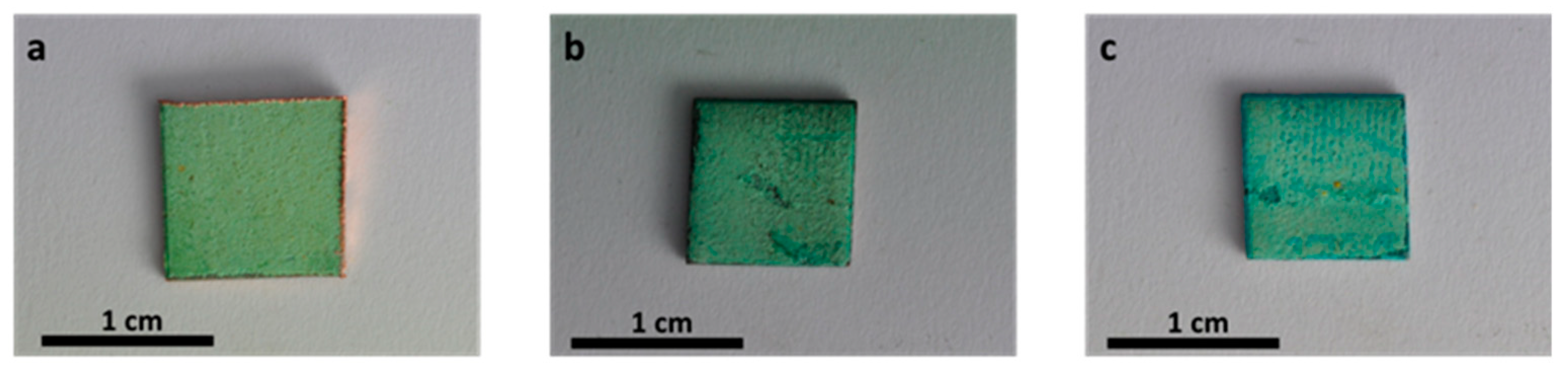
2.1. Samples

The samples were supplied by LRMH Laboratory (Laboratoire de Recherche des Monuments Historiques) and prepared in nearly 1 × 1 cm2 square pieces from the copper roof of Saint Martin church in Metz dated of 1877 that suffered long-term atmospheric corrosion, They consist of pure copper containing micrometric inclusions mostly composed of lead, arsenic, but also antimony, nickel and bismuth from SEM-EDS analyses. The side exposed to atmosphere was easily distinguishable by the characteristic pale green corrosion layer present on top. They were cleaned with ethanol and dried at ambient conditions to eliminate the surface contamination of the sample before proceeding to the organic treatment.

2.2. Carboxylate Protective Treatment

The protective treatment was realized by immersion in a HC10 solution in the laboratory. The solution was prepared by dissolving the decanoic acid HC10 in a mix of water and ethanol in 50/50 proportions in order to obtain a HC10 concentration of 30 g/L. Two dipping times were presently considered, a short time of one minute and a prolonged duration of thirty minutes. Samples were then dried at air for fifteen minutes before being introduced in the oven at 80 °C for the night both to dried the poral network efficiently and avoid any seepage during vacuuming samples but also to efficiently eliminate HC10 residues inside the porous network and make the samples compatible with vacuum and ultra-high vacuum requirement for SEM-EDS and SAM analyses.

2.3. Analyses Methodology

In order to observe the brochantite/cuprite/metal stratification and their corresponding interfaces, the samples were analyzed in cross-section using a multi-technique approach bringing complementary morphological and chemical information from nanometer to micrometer scale. First, optical microscopy and µRS experiments were realized before HC10 treatment to bring an overall description of the CPL layout in depth and determine the nature of the CPL. To facilitate analyses interpretation, polished surface was prepared as follows: Epoxy-resin embedding, cutting and surface polishing with SiC papers (180–4000) and diamond spray (1 μm) under deionized water. Then, for the study of the penetration of the HC10 treatment in the CPL, SEM-EDS and SAM techniques were used. EDS was employed to assess if Cu(C10)2 was present inside the CPL layer and identify areas of interest where SAM, with its high resolution (around 10 nanometer), could evidence the exact penetration depth of the HC10 solution. A different preparation mode was required for EDS and SAM elemental mappings, especially not to confuse the carbon arising from the resin with the one coming from the HC10 treatment and to minimize topographic artifacts. In this case, the samples were prepared without embedding, using a cross-section polisher tool (JEOL IB-09010CP) according to this protocol: a first mechanical polishing with SiC up to grade 4000 using the JEOL Handy Lap and a finishing stage to obtain a mirror-like surface by Ar+ ion abrasion for 3 h in tangential mode at 4 kV for 3 h (ion current = 65 µA). Thanks to those tailored sample preparations, samples could be analyzed without metallization or charge compensation.

2.4. Analytical Techniques

2.4.1. µRaman Spectroscopy (µRS)

µRS measurements were carried out via an Invia Reflex® spectrometer. The incident laser wavelength was of 532 nm and the laser power was filtered down to 0.1 mW. The beam diameter as well as the probed depth were of about 1 µm. The wavenumber resolution of the spectra was of 2 cm−1. The wavenumber calibration of the spectra was obtained from a silicon wafer on the 520.5 cm−1 peak. Acquisition and treatment of the spectra were realized with the software Wire 3.4®. The reference phases analyzed were commercial cuprite Cu2O from Sigma Aldrich and brochantite synthetized according to the procedure described by Kratschmer et al. [18]. The synthesis product was pure brochantite, as confirmed by the XRD diffractogram obtained by Apchain [13]. The Raman spectra are presented without smoothing or line fitting and normalized to help comparison along.

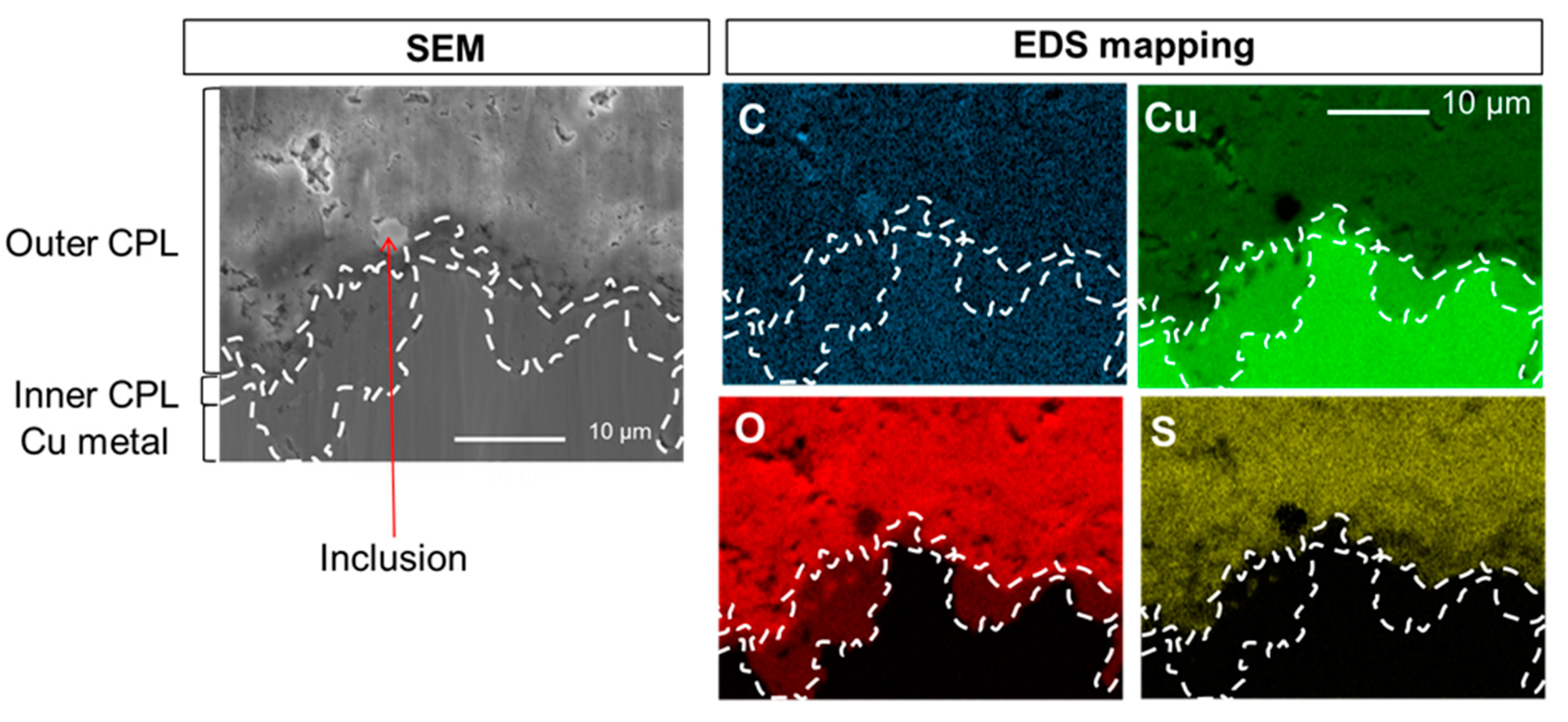
2.4.2. Scanning Electron Microscopy – Energy Dispersive Spectroscopy (SEM-EDS)

SEM micrographs in secondary electron mode and elemental analyses (EDS) were performed using a JEOL JSM 7001F microscope with a patented “in-lens” Schottky Field Emission Gun (FEG) equipped with an OXFORD Aztec EDS system. The experiments were realized with an incident electron beam of 15 kV accelerating voltage and a working distance of 10 mm between the incident beam and the sample surface. C, O, S Kα et Cu Lα lines were considered to realize the chemical maps. Constructor standard database was used for overall quantification when it was needed.

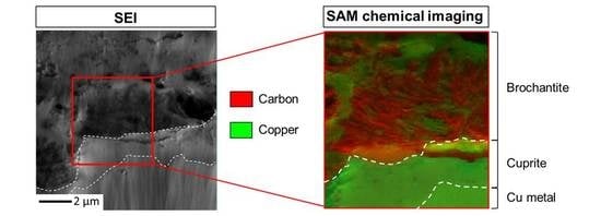
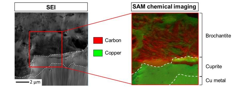
2.4.3. Scanning Auger Microscopy (SAM)

Auger characterizations were performed with a JEOL JAMP 9500F Auger nano-probe also equipped with a patented “in-lens” Schottky Field Emission Gun (FEG) and a hemispherical analyzer (HAS). The ultimate resolutions specified of this equipment are 3 nm (25 kV, 10 pA) for SEM and 8 nm (25 kV, 1 nA) for SAM. Experiments were carried out at 25 kV, 25 nA, tilt 40° leading to 12–15 nm spot size, the maximal analyzed depth being inferior to 4–5 nm. No charge compensation leading to peaks enlargement and energy shifts was used in experiments. In this study, SAM was employed to determine the spatial distribution of the elements inside the CPL with a nanoscale resolution. Local chemical analyses at the interfaces, with a direct access via cross-sections, are presently possible thanks to the inherent beam size of the technique and the quality of the cross-section obtained after ionic polishing, limiting roughness artifacts during SAM measurements. Samples were rapidly transferred to the introduction chamber of the spectrometer just after ion polishing to limit the carbon contamination and oxidation at the surface, detrimental for SAM analyses, which are extremely surface sensitive.

3. Results

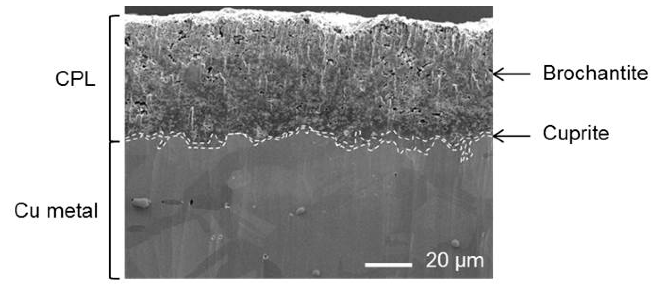
3.1. Nature and Depth Organization of the Corrosion Product Layer

Figure 1a presents the optical microscopy image obtained on the cross-section of a corroded copper sample issued from the roof of the Saint Martin church in Metz and the µRS mapping of the CPL in the selected region. On the optical image, the contrasts clearly enable to separate the CPL (dark contrast) from the copper substrate (light contrast) on which it has grown during air ageing. The CPL is also constituted of two different phases as shown by the two distinct dark contrasts at the metal/CPL interface and at the surface. The typical µRS spectrum evidenced for the inner layer corresponds to cuprite Cu2O through its main peak at 216 cm−1 attributed to the Cu-O bonding (Figure 1c). The characteristic spectrum of the outer layer is attributed to brochantite Cu4SO4(OH)6 well characterized by its main peak at 973 cm−1 corresponding to the symmetric stretching band S-O (Figure 1b). The typical µRS spectrum of the inner layer corresponds to cuprite Cu2O through its main peak at 216 cm−1 attributed to the Cu-O bonding (Figure 1c). The µRS mapping Figure 1a of cuprite (using the main peak at 216 cm−1) and brochantite (using the main peak at 973 cm−1) evidences that the entire inner layer (red) is composed of cuprite whereas the thicker outer layer (green) is only made of brochantite. Our observations are in agreement with the literature: these copper corrosion products have already been reported in studies related to the atmospheric corrosion of copper [19,20,21].
Figure 2 displays the large scale SEM image of the copper sample cross-section where the different phases of the CPL presented previously are even more visible and well preserved by the ion abrasion, pores, grains and inclusion are revealed. Inner cuprite layer of 5–10 µm thickness at the interface with the metal is rather compact although the brochantite outer layer of 20–50 µm thickness is much more porous.
The SEM-EDS elemental mappings of C, Cu, O and S at the CPL/metal interface region of the sample before HC10 immersion are presented on Figure 3. The different phases, metal, cuprite and brochantite, are evidenced on the cartographies and their spatial distribution is distinguishable thanks to the different elements intensities measured and the presence of probe elements. Thus, the presence of brochantite, Cu4SO4(OH)6, in the external part of the CPL is supported by the S mapping showing S is only detected in the outside part of the CPL. In accordance with the relative formula of the different layers, such as Cu, Cu2O and Cu4SO4(OH)6, the variable intensities on the Cu mapping are characteristic of metal (highest intensity), of cuprite (intermediate intensity) and of brochantite (weakest intensity). Conversely, the variable intensities on the O mapping are characteristic of metal (absence of intensity), of cuprite (intermediate intensity) and of brochantite (highest intensity). An inclusion composed of Pb and As is also visible. Even before HC10 treatment, the C, which will be the probe element of HC10 is detected. Here, this C is inherent to the adventitious superficial contamination deposited on the surface in contact with the atmosphere during the transfer from the CP to the SEM. This carbon contamination is rather homogeneous and mainly mimics the topography, the inclusion is harder and higher and appears in a lighter contrast on contrary to the pores. Note that C sticking slightly differs on the CPL (around 12 at.%) and the metal (around 25 at.%) as already observed by SAM but constant in both areas. This C map presents then the background noise which will be present on all the EDS C maps and thus the detection limit of the Cu(C10)2. These results also guarantee that no other carboxylate compounds are detected.

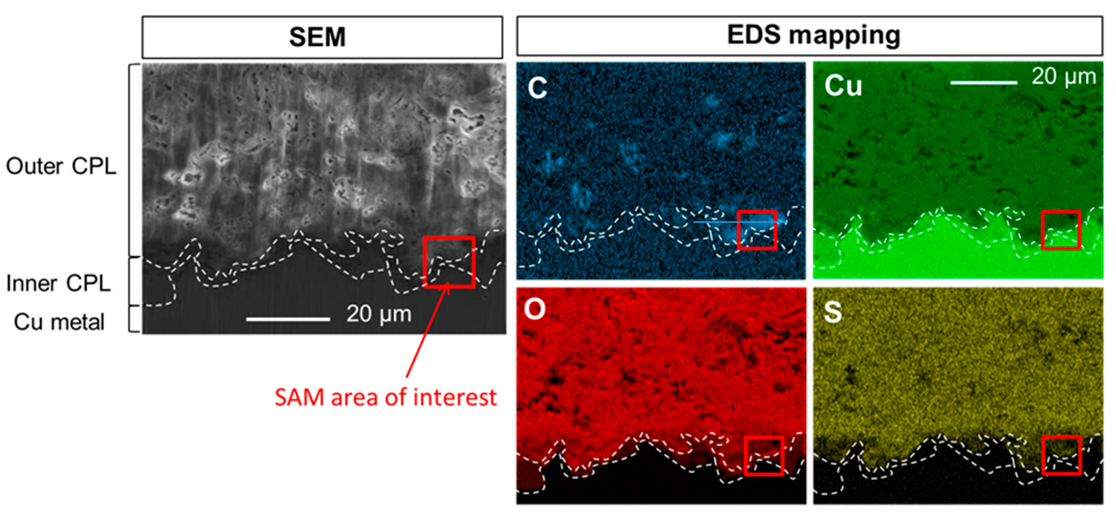
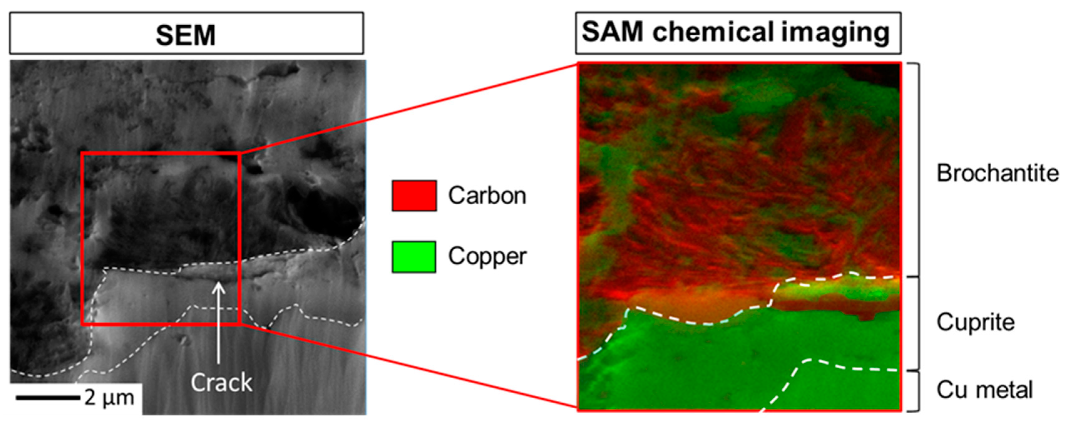
3.2. Penetration of the Carboxylate Treatment in the Corrosion Product Layer

In this study, the penetration of the carboxylate treatment in the corrosion product layer was studied for two immersion times: one minute and thirty minutes. Figure 4 shows pictures of the surface of the samples without immersion and after an immersion of one and thirty minutes in in HC10.
The results obtained for the longer immersion time are presented first as the trends are more pronounced.

3.2.1. Immersion Time in HC10 Solution: Thirty Minutes

First, the SEM-EDS elemental mappings of C, Cu, O and S at the CPL/metal interface region of the sample after 30 min in HC10 solution are shown on Figure 5. As for the sample studied previously, the different CPL layers are clearly identified (dotted lines). Focusing on C, the map presents more visible heterogeneities with higher intensities (until almost 50 at.%) than the one measured on the map before treatment. This clearly evidences C incorporation in specific zones of the brochantite layer, porous, but not in the cuprite layer. To clearly identify whether the HC10 treatment may start penetrating in the cuprite layer, SAM is used to reach chemical information at the nanometer scale and finely determine the Cu(C10)2 formation. Indeed, with EDS, we have succeeded in separating the different phases, delimited by the dotted lines on the maps Figure 5, but with this technique the elemental distribution and especially the one of C for our concern is only accessible at the micrometer scale. A region of interest to realize SAM is identified from EDS mapping (11 µm per 11 µm) and illustrated by the red square on Figure 5.
Figure 6 displays the corresponding magnified SEM image of the region of interest Figure 5, the SAM chemical mapping area of 5.3 µm per 4.9 µm and the overlapping of C and Cu SAM images (C in red and Cu in green) in this area presenting the intensities variation of the C-KLL (263 eV) and Cu-LMM (914 eV) Auger lines. To facilitate the tracking of C within the CPL, the interfaces metal/cuprite and cuprite/brochantite are also indicated by dotted lines on these images. Interpretation of SAM chemical images is simplified when the data acquisition is performed on flat surfaces, enabling to get rid of topography artifacts on the intensities collection (higher intensities in height) and ensure that the intensities variation are only linked to composition modulations. Here, the ion polishing drastically limits such roughness artifacts, and C localization is mainly evidenced in porous areas of the brochantite, not perfectly flat due to this texturation, and the crack observed inside the cuprite on the right side. Auger characterization confirms at the nanometer scale (1pixel ~ 10 nm) what is observed by SEM-EDS at the micrometer scale: carbon is accumulated inside the brochantite pores and the HC10 treatment stops at the cuprite/brochantite interface.

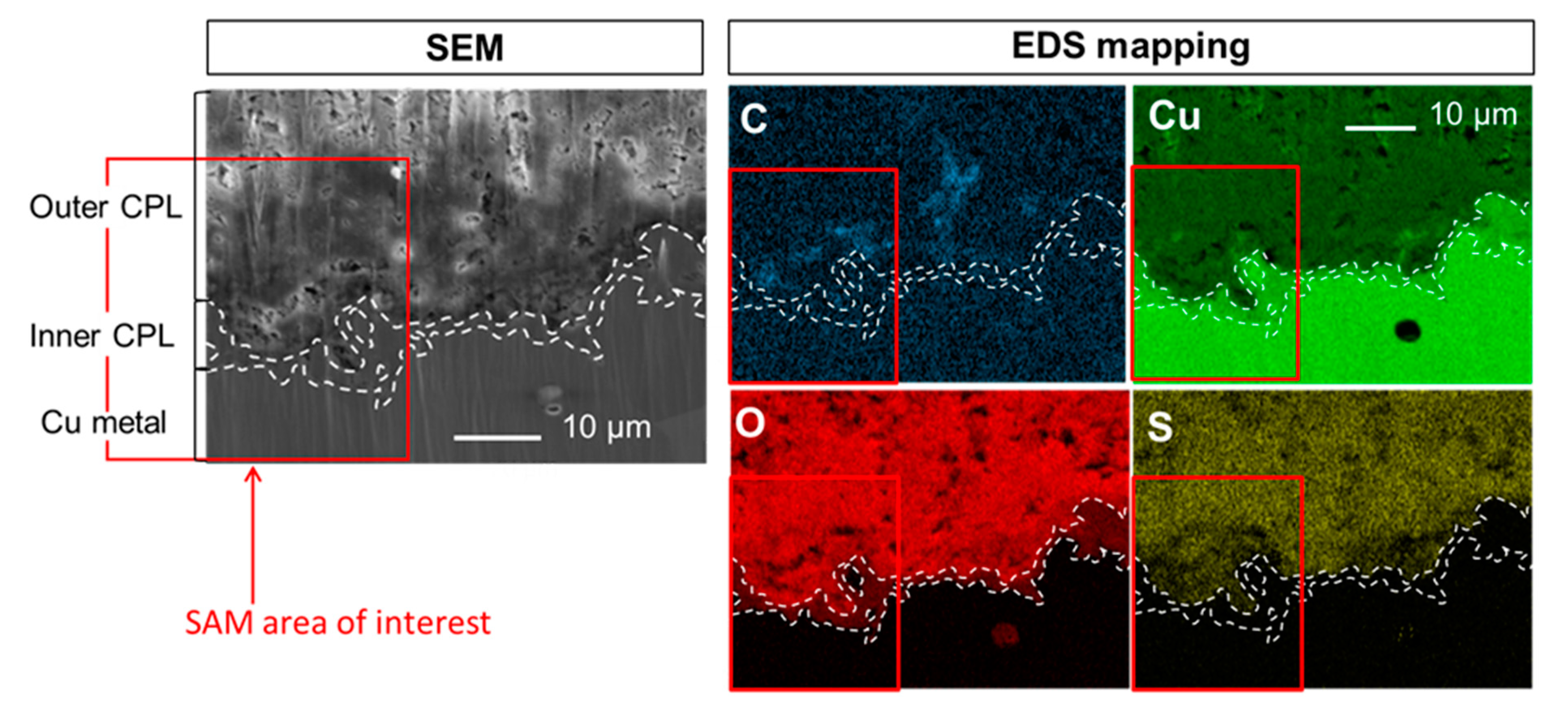
3.2.2. Immersion Time in HC10 Solution: One Minute

Shorter treatment duration has also been studied to investigate the penetration kinetic of HC10 solution, and so, optimize the procedure. The SEM-EDS elemental mappings of C, Cu, O and S in the CPL of the sample after its immersion in HC10 for one minute are displayed on Figure 7. The CPL layers are still clearly identified (dotted lines) and the C seems to be only detected in the brochantite layer. However, it seems less abundant than in the case of the immersed sample for thirty minutes. The red square corresponds to the selected region of interest of 29 µm per 29 µm for complementary SAM fine characterization.
Figure 8 shows the corresponding magnified SE image of the square zone Figure 7, the area for SAM cartography analyses (13.3 µm per 2.2 µm) and the overlapping of C and Cu chemical images (Cu in green and C in red) in this area. The interfaces metal/cuprite and cuprite/brochantite are also indicated on these images (dotted lines). As for the immersion time of thirty minutes, C is only seen in the brochantite layer, principally in the porous parts and stops once again at the brochantite/cuprite interface. This result indicates that the HC10 treatment infiltration is fast, but, after one minute, only partial since conversely to the 30 min dipping C is more locally detected inside the brochantite and at the brochantite/cuprite interface.

4. Discussion

The analytical methodology employed in this paper highlights the complementarity of the analysis techniques chosen, enabling to bring an accurate morphological and chemical characterization of the penetration depth of HC10 treatment in the CPL on copper metal. All the techniques selected present spatial resolutions adapted to the direct analysis on cross-sections, preventing using depth profiling techniques. This brings the advantage to take account for the complex brochantite/cuprite and cuprite/metal interfaces inherent to the irregular CPL growth at the Cu surface (different thicknesses, pores distribution, initial metal surface irregularities, corrosion process…). Thanks to the combine use of µRS, SEM-EDS and SAM, the nature of the CPL and its depth organization can be identified and the HC10 treatment localization can be determined from the micrometer to the nanometer scale. The benefit of the specific cross-section surface preparation by ionic polishing is evidenced since it perfectly reveals the microstructure and interfaces without requiring the use of epoxy resin, that would get into the porous layer of brochantite during the polishing step and hinder the interpretation of the chemical mappings of carbon in CPL whose origin could either be HC10 or resin. In addition, topographical artifacts can be satisfactorily limited. As mentioned in the introduction, such methodological approach, combining complementary techniques for a complete characterization, has already been employed to study the corrosion mechanism of many Cu based artefacts bringing key information for the safeguard [18,19,21]. This paper is another illustration of its real added-value also for the development of new preservation strategies based on the use of innovative corrosion inhibitors presenting lower toxicity.
The results evidence that the corrosion product layer of the copper samples issued from the roof of Saint Martin church in Metz is composed of an inner layer consisting of cuprite covered by a thicker and a more porous outer layer of brochantite, as previously reported in [13]. This two-layer structure is common for copper corrosion and is found in various studies dealing with the atmospheric corrosion of this metal [18,22,23,24]. The presence of an outer sulfur layer of brochantite (Cu4SO4(OH)6) is characteristic of an exhibition in the outdoor environment. Indeed, the formation of the CPL occurs in two stages: the corrosion of copper metal which leads to the precipitation of cuprite (Cu2O) and, when the layer of cuprite is stabilized in thickness [22], the formation of a layer of Cu(II) depending on species present in the atmosphere and in the aqueous film on the surface of the object [18,19,25,26,27,28]. In standard atmospheric conditions Cu(II) ions react with SO2 and SO4 ions present in the atmosphere [29] and a brochantite layer is formed on top of the cuprite one.
Concerning the penetration of the HC10 treatment in the CPL, for the two immersion times studied, one and thirty minutes, SEM-EDS and SAM demonstrate that the treatment is concentrated in the pores of the brochantite layer and is blocked at the brochantite/cuprite interface, without clear evidence of diffusion in the cuprite layer. The treatment duration of the sample has an effect on the HC10 penetration in the CPL as for the immersion time of one minute, the HC10 distribution is more local than for the immersion time of thirty minutes where the treatment is distributed in the whole layer of brochantite. The fact that the HC10 treatment stops at the cuprite/brochantite interface raises the question of the inhibition effect of the HC10 but also of the permeability of the cuprite layer.
Many studies suggest the existence of protective properties of the inner layer of cuprite [22,30,31,32]. This “barrier” effect of the cuprite layer has been put forward previously by the stabilization of the thickness of the cuprite layer over time [22]. We have also demonstrated elsewhere [13], on the base of observations of the copper corrosion by different techniques (optical microscopy, SEM), the lack of microscopic porosity of the cuprite layer compared for instance to the much more porous brochantite outer layer. In addition, for copper samples treated by immersion in HC10 solutions, µRS has evidenced the absence of the main peak characteristic of Cu(C10)2 in cuprite layers whereas it was visible in brochantite layers. Furthermore, the HC10 reacts with corrosion products to form Cu(C10)2, suggesting that the HC10 treatment penetration must be related not only to the porosity properties of cuprite but also to the low reactivity properties of cuprite with HC10 which probably don’t dissolve so easily even in local acidic conditions. From our expertise and the state of the art in the bibliography, the cuprite layer nature influences the treatment efficiency by hindering the penetration of the HC10 treatment. Present results demonstrate that the treatment does not reach the cuprite/metal interface where the anodic reaction governing the corrosion process occurs but the cuprite layer itself, due to its low porosity and chemical reactivity, prevent corrosion phenomenon by forming a protective barrier on the metal. However, as cuprite dissolution may nonetheless occur in some cases, the use of an additional chemical treatment ensures an efficient protection of the object whatever the circumstances.
Finally, these results bring a deeper knowledge on the interaction mechanism between CPL and HC10 corrosion inhibitor, demonstrating that HC10 solution penetrates rapidly inside the brochantite layer (less than 1 min to reach the brochantite/cuprite interface), by means of the numerous pores, leading to the progressive formation of Cu(C10)2 inside the pores. After 30 min, the main part of the pores seems to contain organic precipitate and Cu(C10)2 is also clearly detected at the brochantite/cuprite interface where the HC10 is stopped. Indeed, the inner cuprite layer appears free from Cu(C10)2. This emphasizes the natural barrier effect of the inner cuprite layer, compact and stable, on top of the metal. This also opens interesting perspectives for the protection of copper objects, the major issue concerning the interaction of inhibitors with brochantite to stabilize this layer and prevent infiltration. Different wet organic treatments can be envisaged, to selectively interact with brochantite and form a “second barrier layer” on top of the native cuprite one, while conserving the aesthetic aspect of this outer layer. Due to the ease of use, fast reaction and non-toxicity of these treatments, unlike waxes, varnishes and benzotriazole-type corrosion inhibitors, we show that this type of carboxylate treatment could be used on Cu heritage objects a larger scale. New developments are ongoing as well as ageing studies.

5. Conclusions

An approach based on the use of complementary analytical methods from micrometer to nanometer scale (μRS, SEM-EDS, SAM) is developed in this study to describe the properties of the CPL and the penetration of the carboxylate (HC10) treatment in the CPL of copper samples issued from the roof of Saint Martin church in Metz exposed to atmospheric corrosion. The CPL of the samples consists of a thin layer (1 to 5 μm thick) of cuprite Cu2O on the surface of the metal, followed by a second thicker layer (20 to 50 μm), mainly composed of Cu4SO4(OH)6 (brochantite). The short-term immersion tests (one minute) with HC10 shows that the protection treatment penetrates to the cuprite/brochantite interface but is only detected locally, whereas for a longer immersion time of thirty minutes it is present in the whole brochantite layer, especially in porous regions, and also up to the cuprite/brochantite interface where it appears blocked. In present conditions, the cuprite layer is by consequence not impacted by the carboxylate treatment and these results evidence at the same time the protective properties of this inner layer for the metallic Cu beyond. This indicates also that HC10 selectively interacts with brochantite, where Cu(C10)2 precipitates inside the pores and interstices limiting and preventing further liquid infiltration and corrosion phenomenon. The upper part of the CPL acts as an additional barrier layer, reinforcing the protective action of the inner cuprite layer. These results enable to better understand the HC10/CPL interaction and evidence that the use of organic inhibitor is an interesting route to consider for conservation and preservation issues, less toxic and with possible large scale application.

Author Contributions

Conceptualization, M.B., F.M.-B., D.N., E.A. and M.L.; methodology, M.B., F.M.-B., M.L. and E.A.; software, M.B., F.M.-B., M.L., E.A. and D.N.; validation, M.B., F.M.-B., M.L., E.A. and D.N.; formal analysis, F.M.-B., E.A., M.B., M.L.; investigation, M.B., F.M.-B., M.L., E.A. and D.N.; resources, D.N., P.D., A.E., M.B., and E.A.; data curation, M.L., E.A., M.B. and F.M.-B.; writing—original draft preparation, F.M.-B.; writing—review and editing, F.M.-B., M.B., M.L, D.N. and E.A.; visualization, M.B., F.M.-B., M.L., E.A., D.N., A.E and P.D.; supervision, F.M.-B., M.B., M.L., E.A. and D.N.; project administration, D.N., P.D. and E.A.; funding acquisition, D.N., P.D. and E.A.

Acknowledgments

The authors wish to thank Annick Texier and Aurélia Azéma of the Laboratoire de Recherche sur les Monuments Historiques (LRMH) for providing us the samples from the roof of Saint Martin church in Metz. This work was carried out thanks to a financial support of Fondation des Sciences du Patrimoine.

Conflicts of Interest

The authors declare no conflict of interest.

References

  1. Cano, E.; Lafuente, D. Corrosion inhibitors for the preservation of metallic heritage artefacts. In Corrosion and Conservation of Cultural Heritage Metallic Artefacts; European Federation of Corrosion (EFC) Series; Dillmann, P., Watkinson, D.E., Angelini, E., Adriaens, A., Eds.; Woodhead Publishing: Sawston/Cambridge, UK, 2013; pp. 570–594. [Google Scholar]
  2. Wu, X.; Chou, N.; Lupher, D.; Davis, L.C. Benzotriazoles: Toxicity and Degradation. In Proceedings of the 13th Annual Conference on Hazardous Waste Research, Snowbird, Utah, 19–21 May 1998; pp. 374–382. [Google Scholar]
  3. Pillard, D.; Cornell, J.; Dufresne, D.; Hernandez, M. Toxicity of Benzotriole and Benzotriazole Derivatives to three Aquatic Species. Water Res. 2001, 35, 557–560. [Google Scholar] [CrossRef]
  4. Kim, J.-W.; Chang, K.-H.; Isobe, T.; Tanabe, S. Acute toxicity of benzotriazole ultraviolet stabilizers on freshwater crustacean (Daphnia pulex). J. Toxicol. Sci. 2011, 36, 247–251. [Google Scholar] [CrossRef] [PubMed] [Green Version]
  5. Rocca, E.; Bertrand, G.; Rapin, C.; Labrune, J.C. Inhibition of copper aqueous corrosion by non-toxic linear sodium heptanoate: Mechanism and ECAFM study. J. Electroanal. Chem. 2001, 503, 133–140. [Google Scholar] [CrossRef]
  6. Rocca, E.; Steinmetz, J. Inhibition of lead corrosion with saturated linear aliphatic chain monocarboxylates of sodium. Corros. Sci. 2001, 43, 891–902. [Google Scholar] [CrossRef]
  7. Rocca, E.; Mirambet, F. Corrosion inhibitors for metallic artefacts: Temporary protection. In Corrosion of Metallic Heritage Artefacts; European Federation of Corrosion (EFC) Series; Dillmann, P., Béranger, G., Piccardo, P., Matthiesen, H., Eds.; Woodhead Publishing: Sawston/Cambridge, UK, 2007; pp. 308–334. [Google Scholar]
  8. Rocca, E.; Mirambet, F. Des savons métalliques pour la protection du patrimoine: Sodium carboxylates used to protect metallic artefacts. L’actualité Chim. 2007, 312–313, 65–70. [Google Scholar]
  9. Mirambet, F.; Reguer, S.; Rocca, E.; Hollner, S.; Testemale, D. A complementary set of electrochemical and X-ray synchrotron techniques to determine the passivation mechanism of iron treated in a new corrosion inhibitor solution specifically developed for the preservation of metallic artefacts. Appl. Phys. A Mater. Sci. Process. 2010, 99, 341–349. [Google Scholar] [CrossRef]
  10. Hollner, S. Developpement de Nouveaux Traitements de Protection a Base D’Acide Carboxylique Pour la Conservation D’Objets en fer du Patrimoine Culturel. Ph.D. Thesis, Henri Poincaré University, Nancy, France, 2009. [Google Scholar]
  11. Rocca, E.; Mirambet, F. The electrochemical techniques for the diagnosis and restoration treatments of technical and industrial heritage: Three examples of metallic artefacts. J. Solid State Electrochem. 2010, 14, 415–423. [Google Scholar] [CrossRef]
  12. Hollner, S.; Mirambet, F.; Rocca, E.; Reguer, S. Evaluation of new non-toxic corrosion inhibitors for conservation of iron artefacts. Corros. Eng. Sci. Technol. 2010, 45, 362–366. [Google Scholar] [CrossRef]
  13. Apchain, E. Apport des Traitements Carboxylates à la Protection des Alliages Cuivreux. Ph.D. Thesis, Cergy-Pontoise University, Cergy, France, 2018. [Google Scholar]
  14. Ingo, G.M.; Riccucci, C.; Pascucci, M.; Messina, E.; Giuliani, C.; Biocca, P.; Tortora, L.; Fierro, G.; Di Carlo, G. Combined use of FE-SEM+EDS, ToF-SIMS, XPS, XRD and OM for the study of ancient gilded artefacts. Appl. Surf. Sci. 2018, 446, 168–176. [Google Scholar] [CrossRef]
  15. Ingo, G.M.; Riccucci, C.; Giuliani, C.; Faustoferri, A.; Pierigè, I.; Fierro, G.; Pascucci, M.; Albini, M.; Di Carlo, G. Surface studies of patinas and metallurgical features of uncommon high-tin bronze artefacts from the Italic necropolises of ancient Abruzzo (Central Italy). Appl. Surf. Sci. 2019, 470, 74–83. [Google Scholar] [CrossRef]
  16. Ingo, G.M.; Riccucci, C.; Guida, G.; Pascucci, M.; Giuliani, C.; Messina, E.; Fierro, G.; Di Carlo, G. Micro-chemical investigation of corrosion products naturally grown on archaeological Cu-based artefacts retrieved from the Mediterranean sea. Appl. Surf. Sci. 2019, 470, 695–706. [Google Scholar] [CrossRef]
  17. Carrasco, E.; Oujja, M.; Sanz, M.; Marco, J.F.; Castillejo, M. X-ray and ion irradiation effects on azurite, malachite and alizarin pictorial models. Microchem. J. 2018, 137, 381–391. [Google Scholar] [CrossRef] [Green Version]
  18. Kratschmer, A.; Wallinder, I.; Leygraf, C. The evolution of out copper patina. Corros. Sci. 2002, 44, 425–450. [Google Scholar] [CrossRef]
  19. De la Fuente, D.; Simancas, J.; Morcillo, M. Morphological study of 16-year patinas formed on copper in a wide range of atmospheric exposures. Corros. Sci. 2008, 50, 268–285. [Google Scholar] [CrossRef]
  20. Leygraf, C.; Wallinder, I.O.; Tidblad, J.; Graedel, T. Atmospheric Corrosion, 2nd ed.; John Wiley & Sons: Hoboken, NJ, USA, 2016. [Google Scholar]
  21. Morcillo, M.; Chang, T.; Chico, B.; de la Fuente, D.; Odnevall Wallinder, I.; Jiménez, J.A.; Leygraf, C. Characterisation of a centuries-old patinated copper roof tile from Queen Anne’s Summer Palace in Prague. Mater. Charact. 2017, 133, 146–155. [Google Scholar] [CrossRef]
  22. Fitzgerald, K.P.; Naim, J.; Skennerton, G.; Atrens, A. Atmospheric corrosion of copper and the colour, structure and composition of natural patinas on copper. Corros. Sci. 2006, 48, 2480–2509. [Google Scholar] [CrossRef]
  23. Graedel, T.E.; Nassau, K.; Franey, J.P. Copper patinas formed in the atmosphere-I. Introduction. Corros. Sci. 1987, 27, 639–649. [Google Scholar] [CrossRef]
  24. Wallinder, I.O.; Leygraf, C. A study of copper run off in an urban atmosphere. Corros. Sci. 1997, 39, 2039–2052. [Google Scholar] [CrossRef]
  25. Vernon, W.H.J.; Whitby, L. The open-air corrosion of copper: A chemical study of the surface patina. J. Inst. Met. 1929, 42, 181–202. [Google Scholar]
  26. Oesch, S.; Faller, M. Environmental effects on materials: The effect of the air pollutants SO2, NO2, NO and O3 on the corrosion of copper, zinc and aluminium. A short literature survey and results of laboratory exposures. Corros. Sci. 1997, 39, 1505–1530. [Google Scholar]
  27. Rice, D.W.; Peterson, P.; Rigby, E.B.; Phipps, P.B.P.; Cappell, R.J.; Tremoureux, R. Atmospheric corrosion of copper and silver. J. Electrochem. Soc. 1981, 128, 275–284. [Google Scholar] [CrossRef]
  28. Oesch, S.; Heimgartner, P. Environmental effects on metallic materials–results of an outdoor exposure programme running in Switzerland. Mater. Corros. 1996, 47, 425–438. [Google Scholar] [CrossRef]
  29. Fitzgerald, K.P.; Nairm, J.; Atrens, A. The chemistry of copper patination. Corros. Sci. 1998, 40, 2029–2050. [Google Scholar] [CrossRef]
  30. Vernon, W.H.J. Second experimental report to the atmospheric corrosion research committee (bristish non-ferrous metals research association. Trans. Faraday Soc. 1927, 23, 113–183. [Google Scholar] [CrossRef]
  31. North, R.F.; Pryor, M.J. The influence of corrosion product structure on the corrosion rate of Cu-Ni alloys. Corros. Sci. 1970, 10, 297–311. [Google Scholar] [CrossRef]
  32. Texier, A. La sculpture monumentale en cuivre et alliages cuivreux. In Monumental. Revue Scientifique et Technique des Monuments Historiques; Editions du Patrimoine: Paris, France, 2010. [Google Scholar]
Figure 1. Optical microscopy image of the CPL grown on the Cu substrate and µRS mappings of brochantite (green) and cuprite (red) phases (a) and their respective corresponding spectra (b,c).
Heritage 02 00162 g001
Figure 2. SEM image in secondary electron mode.
Heritage 02 00162 g002
Figure 3. SEM image in secondary electron mode and EDS elemental mappings of C, Cu, O and S at the CPL/metal interface.
Heritage 02 00162 g003
Figure 4. Pictures of the samples surface without and with immersion in HC10 for different times: No treatment (a), 1 minute (b) and 30 min (c).
Heritage 02 00162 g004
Figure 5. Sample immersed in HC10 for thirty minutes: SEM image in secondary electron mode and EDS elemental mappings of C, Cu, O and S at the CPL/metal interface.
Heritage 02 00162 g005
Figure 6. Sample immersed in HC10 for thirty minutes: SEM image and SAM analysis area (5.3 µm per 4.9 µm) (a), overlapping of C and Cu chemical images (b).
Heritage 02 00162 g006
Figure 7. Sample immersed in HC10 for one minute: SEM-EDS elemental mappings of C, Cu, O and S at the CPL/metal interface.
Heritage 02 00162 g007
Figure 8. Sample immersed in HC10 for one minute: SEM image and SAM analysis area (13.3 µm per 2.2 µm) (a), overlapping of C and Cu chemical images (b).
Heritage 02 00162 g008

