
A Novel True Random Number Generator in Near Field Communication as Memristive Wireless Power Transmission


1
Department of Electronic Engineering, University of York, Heslington, York YO10 5DD, UK
2
School of Information Science and Engineering, Changzhou University, Changzhou 213164, China
3
The City of Liverpool College University Center, School of Engineering and Green Technologies, Liverpool L3 6BN, UK
4
Department of Electrical Engineering and Electronics, University of Liverpool, Liverpool L69 3GJ, UK
*
Author to whom correspondence should be addressed.
J 2021, 4(4), 764-783; https://doi.org/10.3390/j4040052
Submission received: 22 September 2021
/
Revised: 20 October 2021
/
Accepted: 27 October 2021
/
Published: 11 November 2021
(This article belongs to the Section Computer Science & Mathematics)
Abstract
:The security of powering systems has been a major problem over the last decade, leading to an increased interest in wireless power and data transfer. In this research paper, a new inductive Wireless Power Transfer (WPT) circuit topology has been used. In traditional WPT circuits, the inverters are used to produce an oscillation for the transmitter coils. The classic WPT system includes intrinsic energy dissipation sources due to the use of switches, necessitating the need of an extra control circuit to ensure proper switching time. Furthermore, they have limited data encryption capabilities. As a result, an unique WPT system based on memristors has been developed, eliminating the need for switches. Furthermore, because this novel topology communicates a synchronised chaotic behaviour, it becomes highly beneficial. This circuit may be used in Near Field Communication (NFC), where chaotic true random numbers (TRNG) can be generated to increase security. The results of simulations indicate the functioning of the Memristor-based WPT (M-WPT) and its ability to generate random numbers. We experimentally proved the chaotic behaviour of the circuit and statistically demonstrated the development of the TRNG, using an Arduino board and the Chua circuit to build the M-WPT circuit.

1. Introduction
Security in wireless communication is increasingly becoming important for wireless power transfer (WPT) systems in order to preserve the data transmitted. The WPT adopts inductors for the transmission in most of the applications and it is also known as Inductive Power Transfer (IPT), due to the transmission being made by mutually coupled inductors. Increasing the security in these systems creates an opportunity for numerous new applications. An useful application of this technique is an access card, or any other short-range data encryption. There are many technical achievements in WPT systems, but they are mostly based on the working principles, circuit topology, and transfer efficiency [1,2,3]. The energy transferred is mostly without any control on the receiver [4,5,6].
The inductive link is able to integrate power and data together [7] and thanks to its short-range functionality, it offers more security in communication. Despite the short distance, there is an inevitable risk of energy and data theft. Some solutions provide a selective WPT technology made by switching capacitors in order to achieve an oriented power transmission to a specified receiver among the unauthorised receivers [8,9].
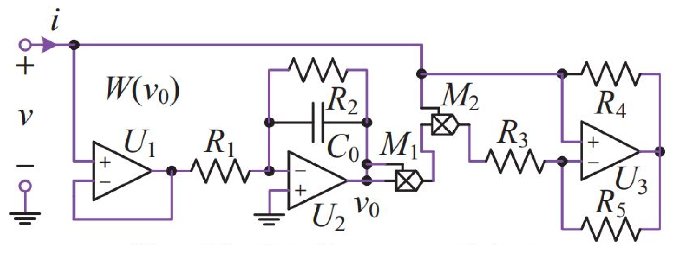
The memristor (portmanteau of memory resistor) is a non-linear electrical element based on the electric charge q and magnetic flux theorised by Prof. Leon Chua [10]. This element shows a pinched hysteresis loop characteristic and has the ability to store charge as a memory [11,12]. It has been applied to the well-known Chua circuit, which is a simple circuit consisting of five components, one of which is the memristor, as shown in Figure 1. Because the memristor is not commercially available, we use electrical circuits equivalent to the device called a memristor emulator, or model. The real memristor has similar behaviour and possesses all the qualities mentioned in the paper, but it is not available in any simulation library. There are many different models of memristor studied by the scientific community and used for different types of circuits. The non-ideal active voltage-controlled model, shown in Figure 2, has proven to generate different types and orders of chaos by small variations of parameters.
Therefore, this device can be adopted to the existing linear or nonlinear electronic circuits in order to create several new chaotic circuits [13,14]. This circuit is also known to produce chaotic behaviour. In general, chaotic networks demonstrate unpredictable and complex dynamic behaviour. Their states oscillate around certain attractors and jump from one trajectory to the next at random intervals, with no discernible pattern. The obtained dynamical behaviours are chaotic with coexisting multiple attractors [15,16], and hidden attractors [17,18,19].
In this work, we are introducing a memristor which creates the oscillation of the LC resonance instead of the traditional switches. Furthermore, it is not necessary to add an external circuit to drive switches and there will be no issues related to timing. In addition, thanks to the special non-linearity and memory characteristics of the memristor, it is possible to adopt a key based mutual authentication on the last status and its subsequent encryption and decryption.
Therefore, we propose a memristor-based architecture for WPT systems. The system possesses the quality of transmitting chaos wirelessly without using any switches and driving circuitry. Furthermore, the system will not be predictable by algorithm; therefore has the possibility of achieving the highest level of encryption based on the last state of the memristor. The remaining of the paper is organised as follows. The application as a near field communication and the functionality are shown in the next Section 2. In Section 3, there are an analysis of the stability of the Chua circuit and principles of WPT. The working mechanism of the memristor-based WPT with simulation and practical results are presented in Section 4. Finally, the proposed circuit with chaotic waveform is real time sampled by Arduino board and Python application which are discussed in experiment part of the Section 4.3.
2. Wireless Power Transfer and Memristor
The Near Field Communication (NFC), which is a WPT system, is very sensible about the encryption problem and it is largely used in contactless credit cards, smartphones, and digital keys. NFC is a bidirectional, low-bandwidth wireless communication technology which uses electromagnetic induction to transmit information. This technology also allows data to be exchanged between devices separated by a distance of up to 10 cm [20]. In Figure 3, we show NFC technology in some security uses: a security safe lock with an NFC system opening key is available as a commercial product. The opening door of a vehicle and its usage as a key for home’s handle. The receiver harvests energy as well as transmits and receives data from the transmitter. The access cards and digital keys have internal data encrypted via software and stored in the device memory. This encryption is traditionally based on the Hash function algorithm [21,22]. This type of algorithm is well known and it is largely available on the internet. In high security applications, it is necessary that such important data be protected by an internal electronic device. Therefore, we introduced an NFC system built on a memristive circuit able to produce a chaotic waveform. There are three great advantages of memristors, which are used in this WPT application:
- It generates less heat than transistors or switches.
- It is capable of storing charge and remember its last state.
- It is possible to develop chaotic behaviour.
Table 1 shows a comparison between traditional WPT in NFC applications and the new topology introduced in the current article. Both systems work on harvested energy and have the same range. On the other hand, the traditional WPT allows multi-receivers and is prone to Man-in-the-Middle (MitM) attacks. Whereas, the WPT system with memristors can communicate only with one receiver, being immune to MitM attacks, and does not require external circuits to drive timing for switches, and it is able to create highly encrypted protection. Moreover, it is not based on algorithms that can be software hacked. The waveform generated is chaotic and it is based on the last state of the state variables. Every time that the system reads from the memristor, it will bring the internal state of the memristor to a different point of stability, which is completely chaotic and not correlated with the previous one.
Similarly to the NFC contactless payment, the M-WPT system will have a digital IC managing the data and creating the synchronisation protocol of communication. However, this is a further development for a specific application where manufacturers will apply in a successive stage.
To our knowledge, there are no records about this type of system. In the scientific literature, although a lot of security authentication schemes for NFC are presented, researchers have created protocol protections or solutions for a single electronic device. Random number generation (RNG) is the most widely adopted method for cryptography. This method can be classified into two categories, namely Pseudo Random Number Generator (PRNG) and True Random Number Generator (TRNG). The PRGN is based on the mathematical implementation of electronic devices through logic functions [24,25]. The TRNG is a hardware component that generates numbers by relaying on the intrinsic stochasticity of the physical variables as a source of randomness. For example, thermal or bust noise in electronic devices is often exploited by TRNGs methods [26,27]. None of these solutions are based on the synchronisation of chaos between a transmitter and receiver. The most advanced security in NFC is using internet third-party verification [28]. The memristor has also been efficiently used in imaging and communication encryption, ref. [29] providing the highest level of encryption achieved. In a memristor-based chaotic cryptosystem model, a chaotic circuit is critical to decide the chaotic encryption and decryption. For example, an user key, which is defined by initial values resulting in chaos of the memristor circuit, is given a chaotic sequence generation. Then, the encryption and decryption are developed from this sequence. Therefore, it is possible to combine the WTP technology and a memristor-based chaotic circuit by synchronising the two devices.
One of the notable advantages of the system proposed is shown in the last part of Table 1. The system proposed allows only one receiver during the transmission of data. If more than one receiver tries to connect, it will create an imbalance in the circuit and the communication will immediately stop.
Typical Functionality
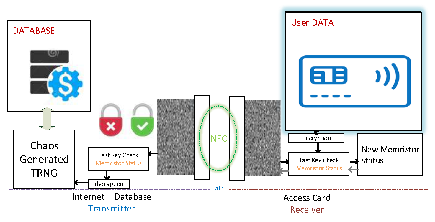
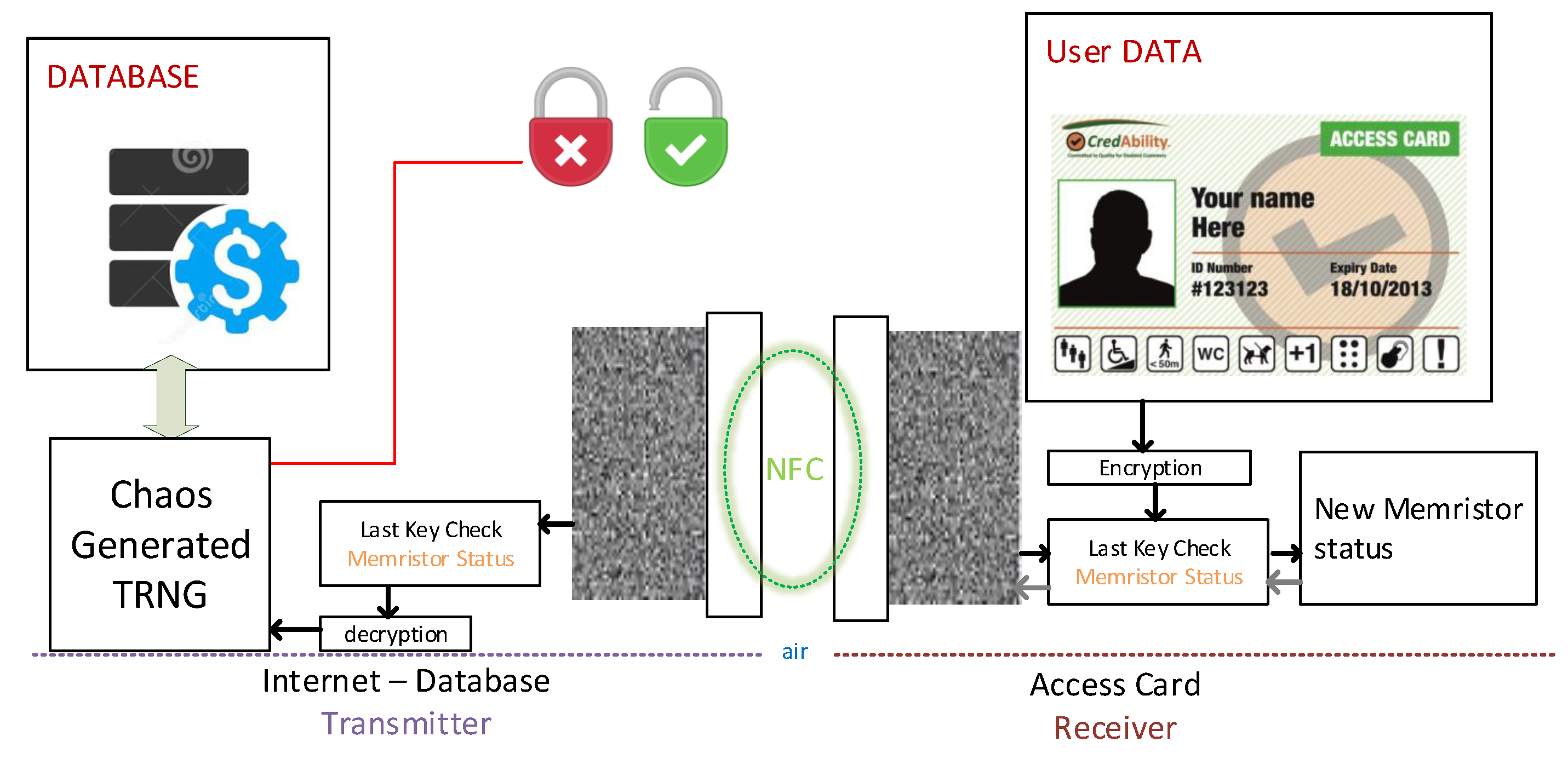
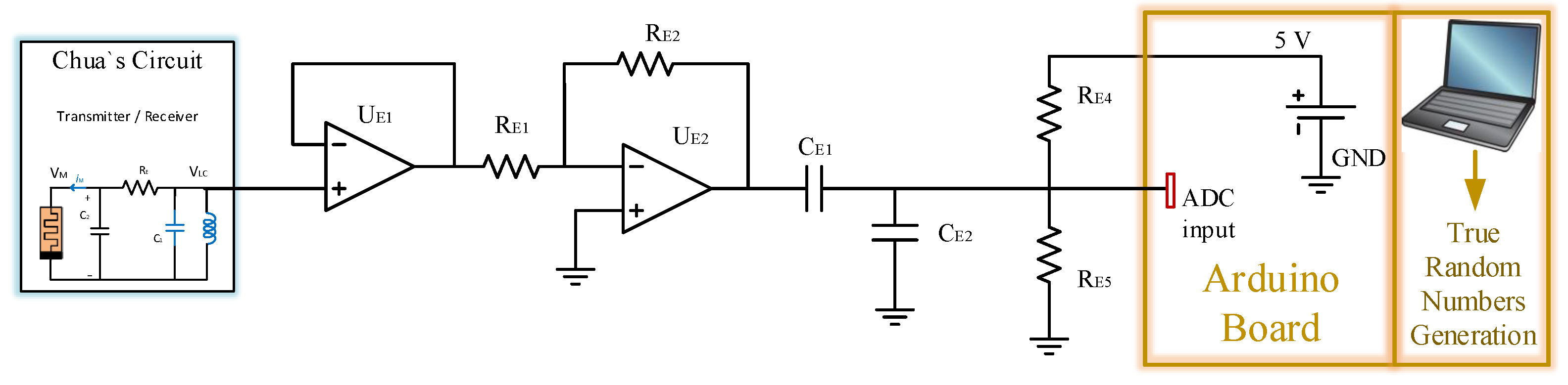
The memristor-based chaotic cryptography system model consists of two parts, as shown in Figure 4. These are two symmetrical copies of the Chuas circuits shown in Figure 1, and they are mutually inducted in air; hence composing the M-WPT system shown in Figure 5. In a typical Chua circuit, the initial condition is applied to the capacitor from an external digital source. Therefore, in the and there is a connection to A/D or D/A converter. According to the cryptosystem model shown in Figure 6, the process of creating a chaotic encryption key for opening safety data is described as follows:
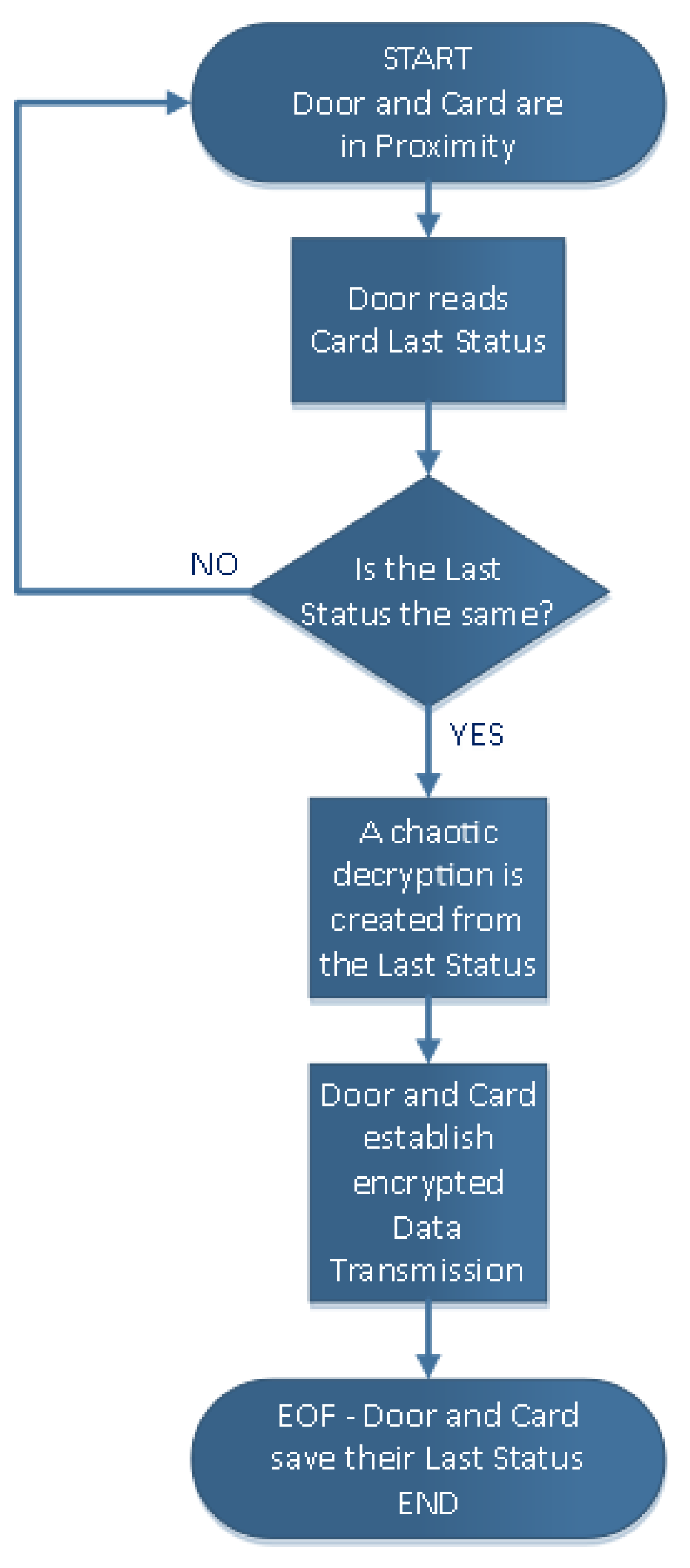
Step 1—The door lock has been configured from a customer’s database and has in memory the last status of the Memristor. The Access Card has an internal ID code encrypted by the last Memristor chaotic status.
Step 2—When the transmitter and receiver are close enough, the card harvests energy from the door lock, and it is active to start a new chaotic oscillation depending on its last status. Similarly, the door lock will synchronise with the card and its last status.
Step 3—The last status of the card is compared with the door lock memory. If the last status coincides with the expected value, the system can decrypt and encrypt data. Otherwise, the last status of the card is modified to an unrecognisable value and any other attempt will not go over step 3. There are thousands of combinations in only one memristor, and the internal value can not be manipulated or read via software or algorithms.
Step 4—When it is successful, the communication is established and the data keys are transmitted.
Step 5—At the end of the payload, both digital parts will disconnect the memristor, storing their last status. The door key stores a copy of the last status of the Access Card memristor.
It is important to clarify to the readers that the transmitter and receiver do not generate the same sequence of random numbers. However, they will generate a synchronised chaotic behaviour which depends on the last status of the receiver’s memristor (internal state variable).
As mentioned above, any forgery attempt on the digital access card will leave an indelible mark as it will bring the memristor internal status to an unexpected value for the authentication key in a safe security lock. There is no possibility of coming back to the previous status. In spite of the fact that the electronic system could be cloned, the internal value of the memristor can never be predicted and there is no algorithm that could predict this value.
3. Stability and Chaotic Behaviour
An important analysis needs to be completed on the memristor state value variables and the chaotic behaviour.
3.1. Memristor State Variables
It is important to show that the system has no variation from the memristive Chua’s circuit; therefore, it is stable. Both parts of the system must be able to develop chaotic behaviour when they are in proximity to each other. The behaviour of the circuit derives from the classical third-order Chua’s circuit by replacing it with the non-ideal active voltage-controlled memristor shown in Figure 1. The latter is composed of a buffer , an integrator connected two resistors , , the capacitor , the multipliers and , and a current inverter linked to resistors , , and . This model is described by the two equations:
where is the current flowing in the memristor, is the voltage on the memristor and the voltage on its internal capacitor . In addition, the scale factors of the multipliers and are indicated as and in order to have and . These relationships provide the memristor input–output characteristics and the pinched relationship [15].
3.2. Theoretical Analysis
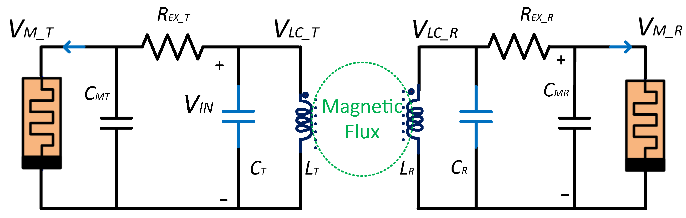
Similarly to memristive Chua’s circuit, each side has four dynamic elements: the parallel LC with the mutual inductor and the parallel of the non-ideal active voltage-controlled memristor W and a capacitor . Thanks to the symmetry, it is possible to consider one side. It results in four state variables: , , , and . Therefore, a system of equations for one side can be written as:
where the voltage on the capacitor coincides with the one on the memristor . The system has a zero equilibrium point and two non equilibrium points indicated as:
where and is the resistance between the coil parallel and memristor. The nonzero equilibrium points are symmetrical with respect to the origin and disappear when < (1.4 k). For the k and it can be demonstrated that it is always unstable.
From the equation set (3), a simplified equation set can be defined by using as a non-linear function. By using the values in the Table 2 and Table 3, it is possible to define new dimensionless parameters , , , , , , , , , and . This will result in , , , , and and the chaotic behaviour will develop. When the parameter varies in the range of 8 to 15, the four Lyapunov exponents, calculated by Wolf’s method [30], the bifurcation diagrams with coexisting bifurcation modes and the dynamics featured are plotted in Reference [13]. The memristive Chua system has two stable nonzero saddle-foci and shows a remarkable dynamical behaviour of multiple attractors with multistability. The full complex dynamics are investigated theoretically and numerically in the Reference [13]. Further variations will not be studied because they are outside the purpose of this paper.
3.3. Wireless Power Transmission
The WPT system built with memristors is shown in Figure 4. The memristive Chua’s circuit introduced in Figure 1 has been improved with a mutual coupled inductor and is the compensation capacitor. As depicted in Figure 4, the system is completely symmetrical as two copies of the Chuas circuit. The latter circuit creates an oscillation which can bring about equilibrium, chaos, or instability. In reference to the memristive Chua’s circuit, it has been considered the parameters values shown in Table 2. As notices, the inductors values and are 8 mH which is lower of the usual values in Chua memristive circuits 11.8 mH. It is possible to use a lower value because of mutual induction. The current flowing in or the transmitter coil sets up a magnetic field which passes through the receiver coil ; thus, giving us mutual inductance. When the inductances of the two coils are the same and equal, is equal to , the mutual inductance that exists between the two coils will equal the value of one single coil (as the square root of two equal values is the same as one single value) as shown:
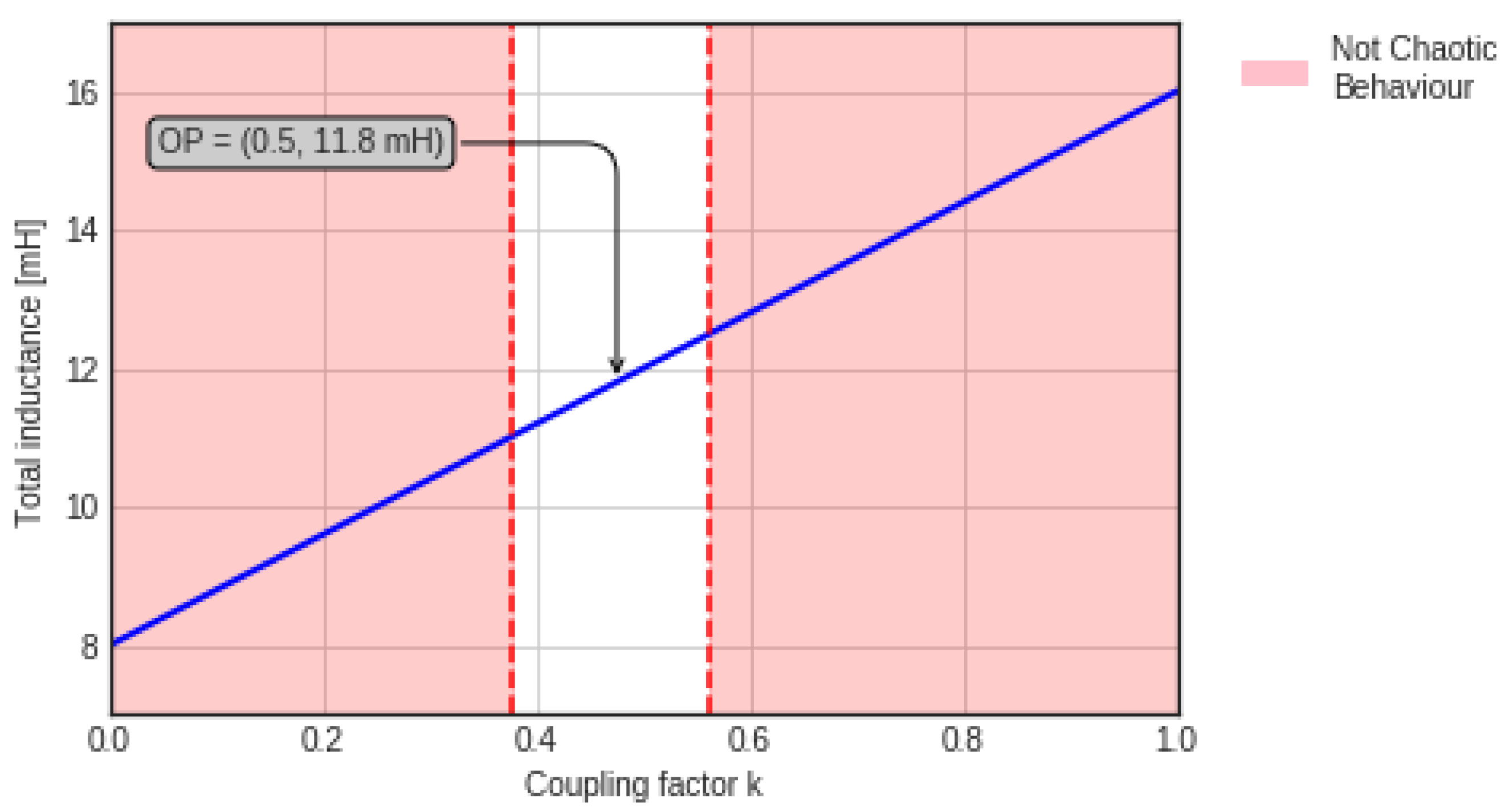
where k is the coupling coefficient expressed as a fractional number between 0 and 1, where 0 indicates zero or no inductive coupling, and 1 indicates full or maximum inductive coupling. The system does not develop chaotic behaviour for all values of total inductance, but only for certain values of the coupling factor. In our application, the coupling coefficient is in a range between 0.4 and 0.6, as represented in Figure 7. A lower or higher value of coupling is not enough to start chaotic behaviour and to change the status of the memristor. As it can be seen, if the inductance goes over a certain value, the system will not oscillate because of an over-inductive value. Outside of a certain range, the system does not develop chaos and does not oscillate. This makes the system robust to additional receivers and also immune to MitM attacks. One coil induces a voltage in an adjacent coil; therefore, the transmitter induces a voltage in the receiver, and vice-versa.
Using these relationships, it is possible to adopt lower inductances than the Chua’s circuit. Furthermore, the symmetry of the circuitry allows transmission of the chaotic behaviour. The transmitter and receiver will resonate at the same frequency:
which adopting the values reported in Table 3 gives 6.8 kHz. It is important to notice that this application is not necessary to achieve high efficiency. The receiver needs low enough power to start its own oscillation and chaotic behaviour necessary for encryption.
4. The Proposed Circuit and Algorithm
In security applications, the distance between transmitter and receiver is within a short range. To assess the system created, different experiments have been used. Initially, the magnetic field propagation has been analysed. Secondly, the electrical circuit simulations are performed. Later, the circuits will be built and tested. During the functionality, an Arduino electronic board samples the chaotic behaviour and generates a True Number Random Generator.
4.1. Magnetic Field
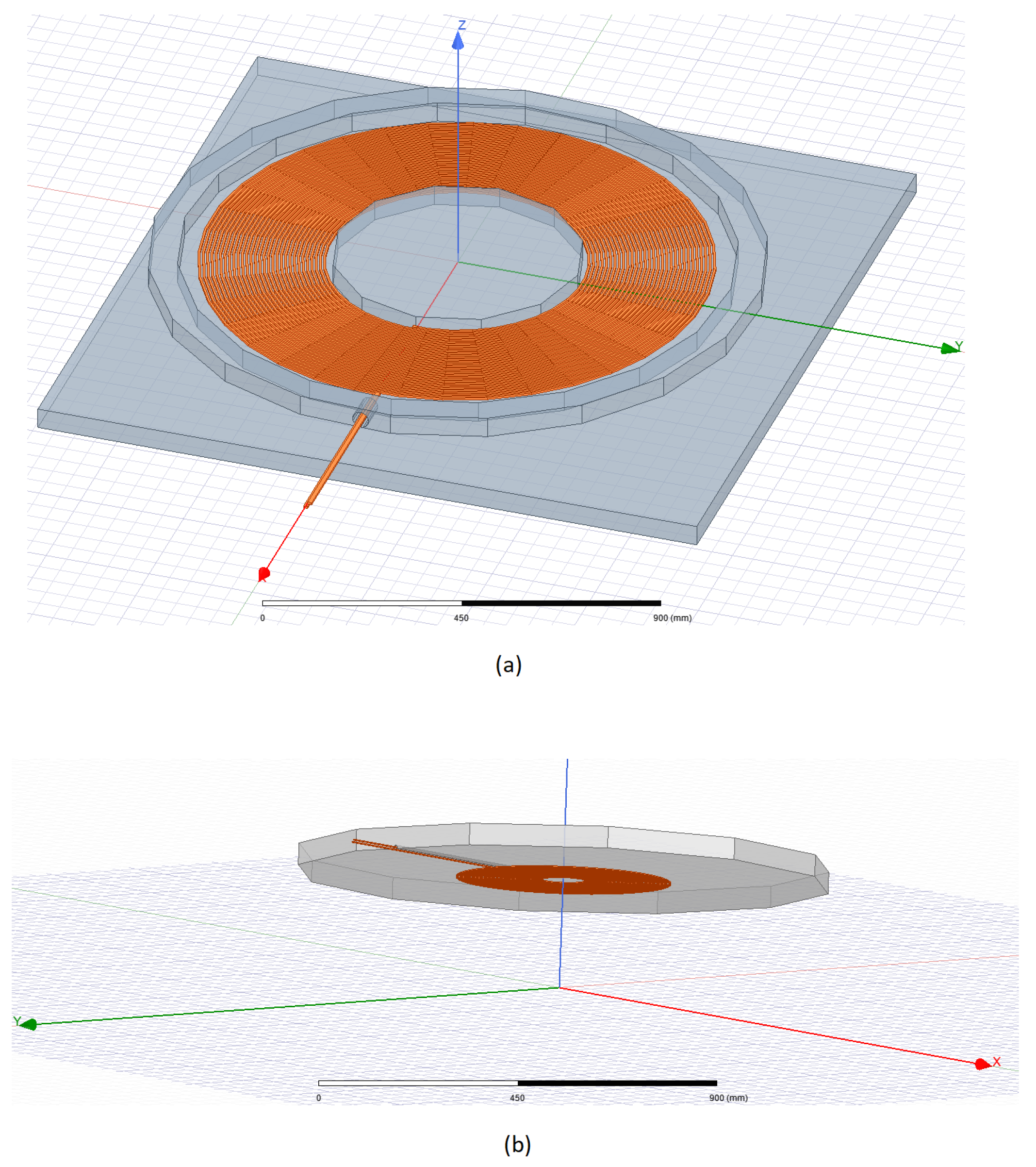
A finite element analysis (FEA) of the coil shape and the magnetic field is performed. One of the most accurate softwares in this type of analysis is ANSYS Maxwell v19. The coils of 8 mH have been designed. A core has been added to the transmitter and receiver in order to achieve higher performance. As shown in Figure 8, the size of the coils is large and they can carry an even larger amount of power. Therefore, it will allow power transmission for longer distances. The main purpose of this simulation is the achievement of the necessary mutual inductance for the chaotic oscillation. Our application has low power characteristics, therefore improvements to the coil technology will be made in future research.
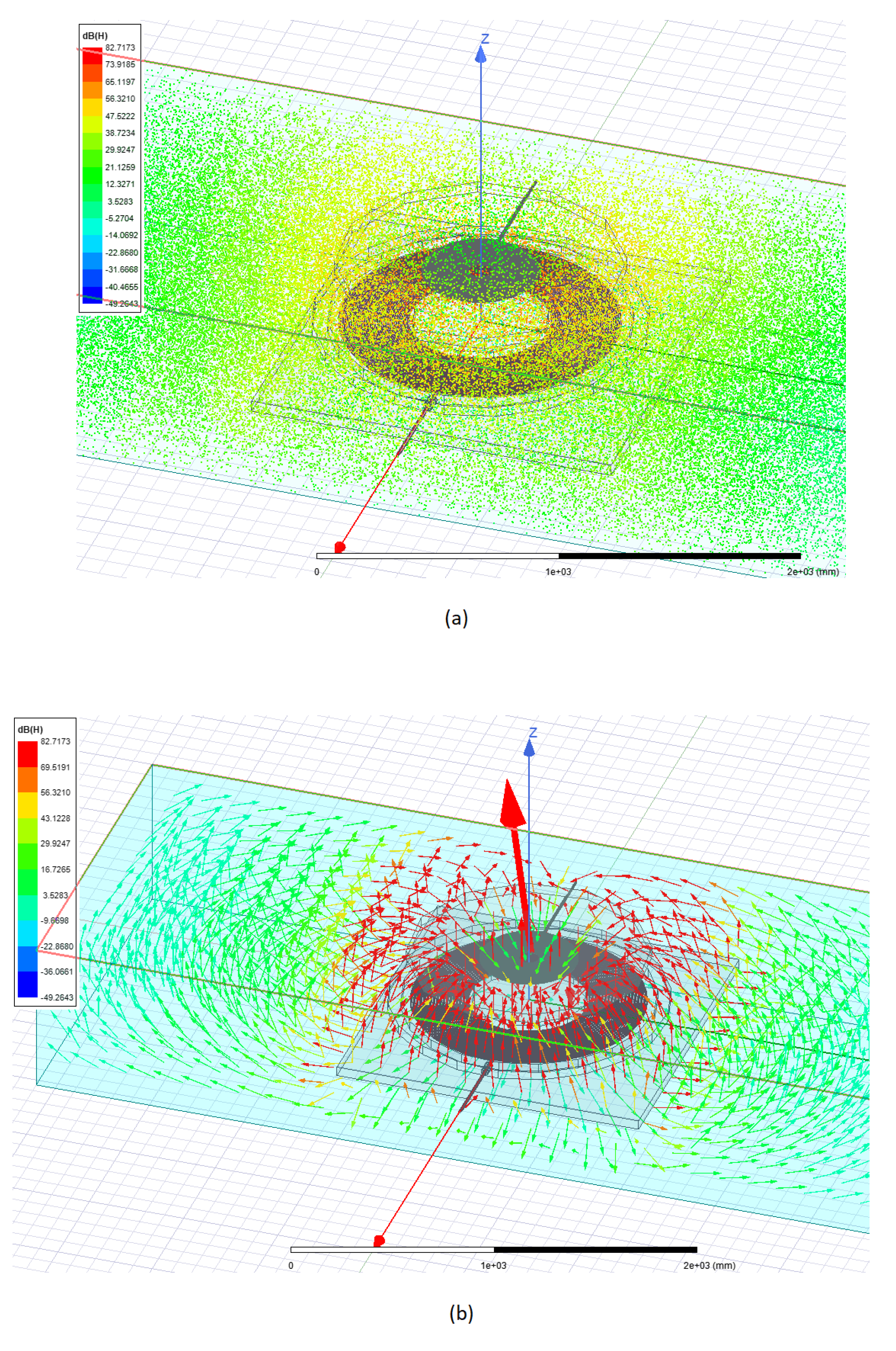
In order to achieve the mutual inductance of 4 mH, simulation results have shown that it is necessary for a gap of 100 mm (air, plastic or any material with relative permeability ) between coils. For security reasons, the transmitter and the receiver are equipped with a directional core. As shown in Figure 9, even when a large amount of power is transmitted, the magnetic field intensity reduces to zero decibels or even lower in the surrounding area.
4.2. Circuit Simulation
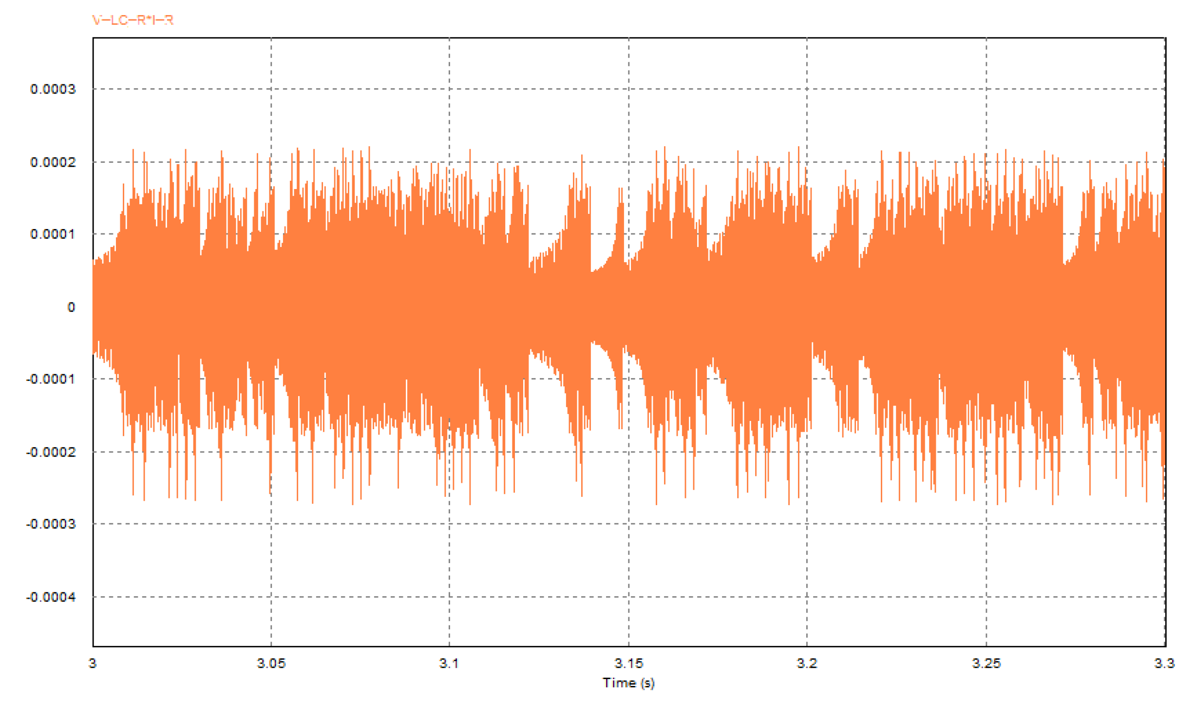
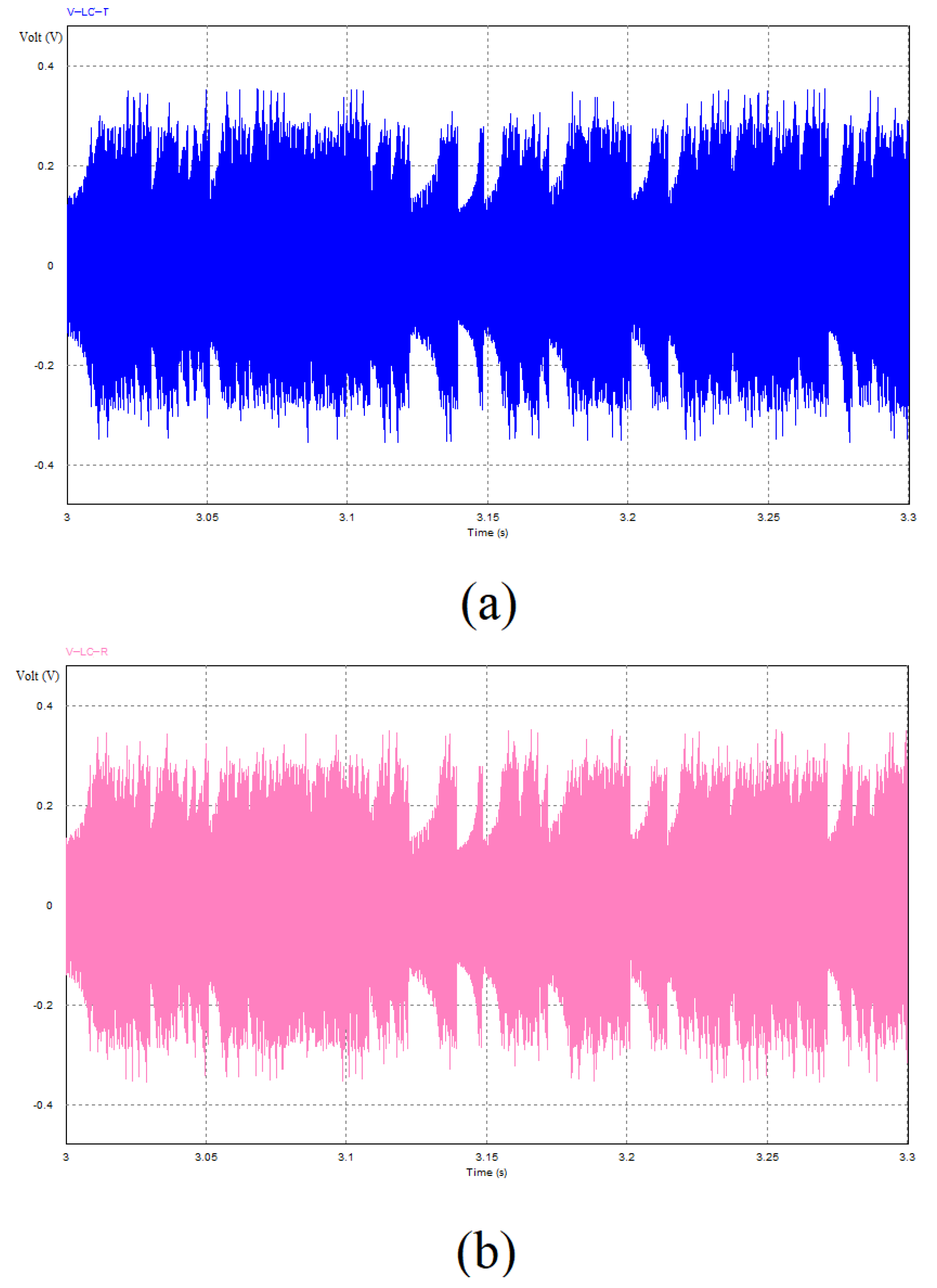
Once we have viewed the magnetic field and its directionality, it is important to focus on the electric circuit. By using PSIM software, it is possible to investigate the performance of the memristor based WPT system. As depicted in Figure 10, the power levels are very low in spite of using an active memristor model. The power behaviour is also chaotic and its maximum level may reach 0.3 mW. The circuit develops a chaotic waveform following Chua’s memristive circuit. The memristor actively creates the chaotic oscillation, which has been plotted in the transmitter coil in Figure 11. The same oscillation is induced in the receiver, creating a synchronous behaviour, as shown in Figure 11.
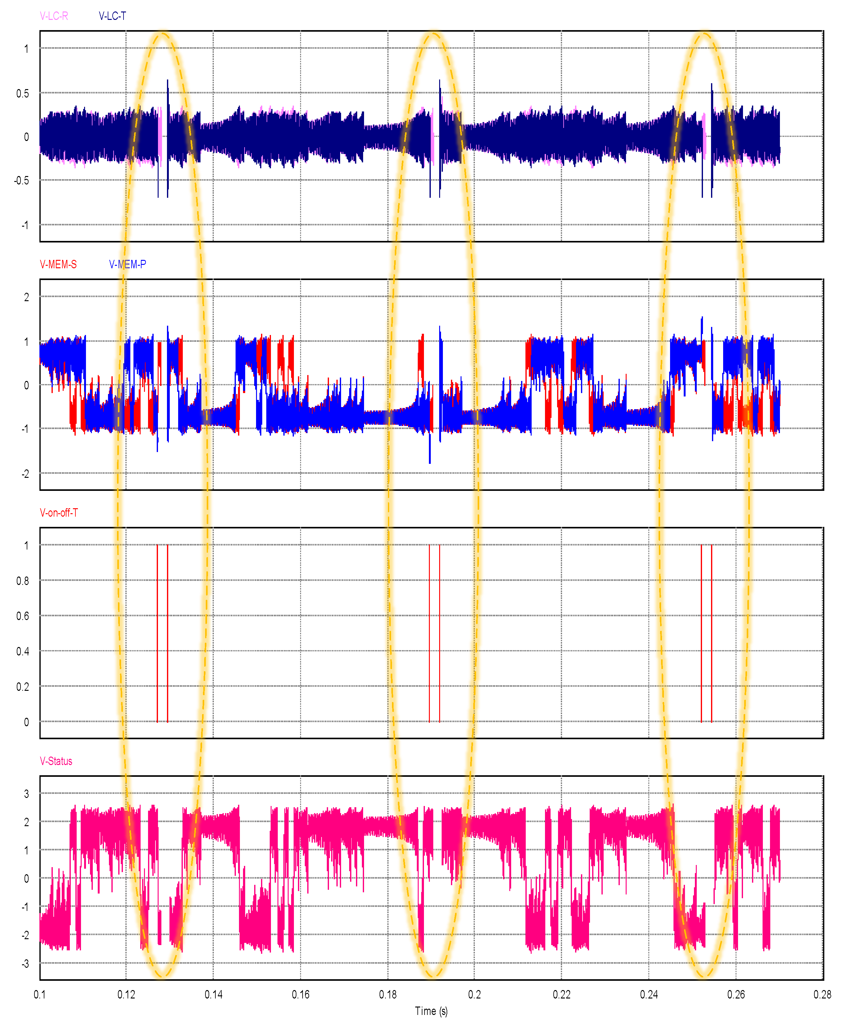
In Figure 12, the voltage in the transmitter coil vs the voltage on the memristor has been plotted. This plot is also known as a phase portrait, and the circuits exhibit a typical two-attractor waveform. In order to test this behaviour in data transmission, we have added a switch that sends data after stopping the oscillation. The voltage on the memristor and the coil stops as highlighted in yellow in the 1st and 2nd graphs of Figure 13. After the circuit behaves chaotically, it stores its previous status (internal memristor voltage 4th graph) as highlighted in yellow at the time of disconnection (red 3rd graph). We have repeated the experiment three times and the internal memristor voltage value (4th graph ) is totally random. For plotting reasons, the time (red 3rd graph) of disconnection is periodic as shown in the Figure 13.
Once we confirmed the functionality, we tested the maximum frequency of the data transmission, in which we could still have chaotic behaviour. The digital data transmitted has all “1” values (1 Volt) using the = input voltage. We reduced the data transmission period to 0.3 ms, thereby increasing the frequency to 3 KHz. The behaviour is still chaotic in the coils as shown in Figure 14. The internal memristor voltage 4th graph always stops at random voltage values. We have also simulated the device to a higher frequency, and it can be noticed that for frequencies over 3.4 KHz, the behaviour on the coils is not chaotic anymore. The reason is that faster variations do not give enough time for the circuit to develop chaotic oscillations. The memristor takes some time to develop its chaotic behaviour, which depends upon its internal values, the capacitor and the oscillation frequency seen in Section 3.
4.3. Experiment
The system is made of two chua circuits where the inductors are mutually coupled. In order to sample the chaotic waveform, it is necessary to adapt this waveform to the dynamic of the analogue to digital converter (ADC). Thus, they have created an additional circuit which keeps the dynamic of the waveform sampled between 0 and 5 V, the Arduino ADC dynamic. As shown in Figure 13, the Chua circuit has low voltage on the coils and (transmitter and receiver) in a range between-0.5V and 0.5V. However, the ADC on the Arduino board has a dynamic range of 0 to 5 V. Negative voltages are not allowed as they can damage the electronic board; therefore, it is necessary to adjust the range.
The adaptor circuit, shown in Figure 15 and Figure 16, is composed of a Voltage Follower or Buffer, an Inverting Amplifier, and a Voltage Divider. The gain of the Inverting Amplifier is set to increase the input voltage to the ADC dynamic range. To protect the ADC from over-voltage or negative voltage, the resistance is a potentiometer that allows the Inverting Amplifier gain to be quickly adjusted as needed.
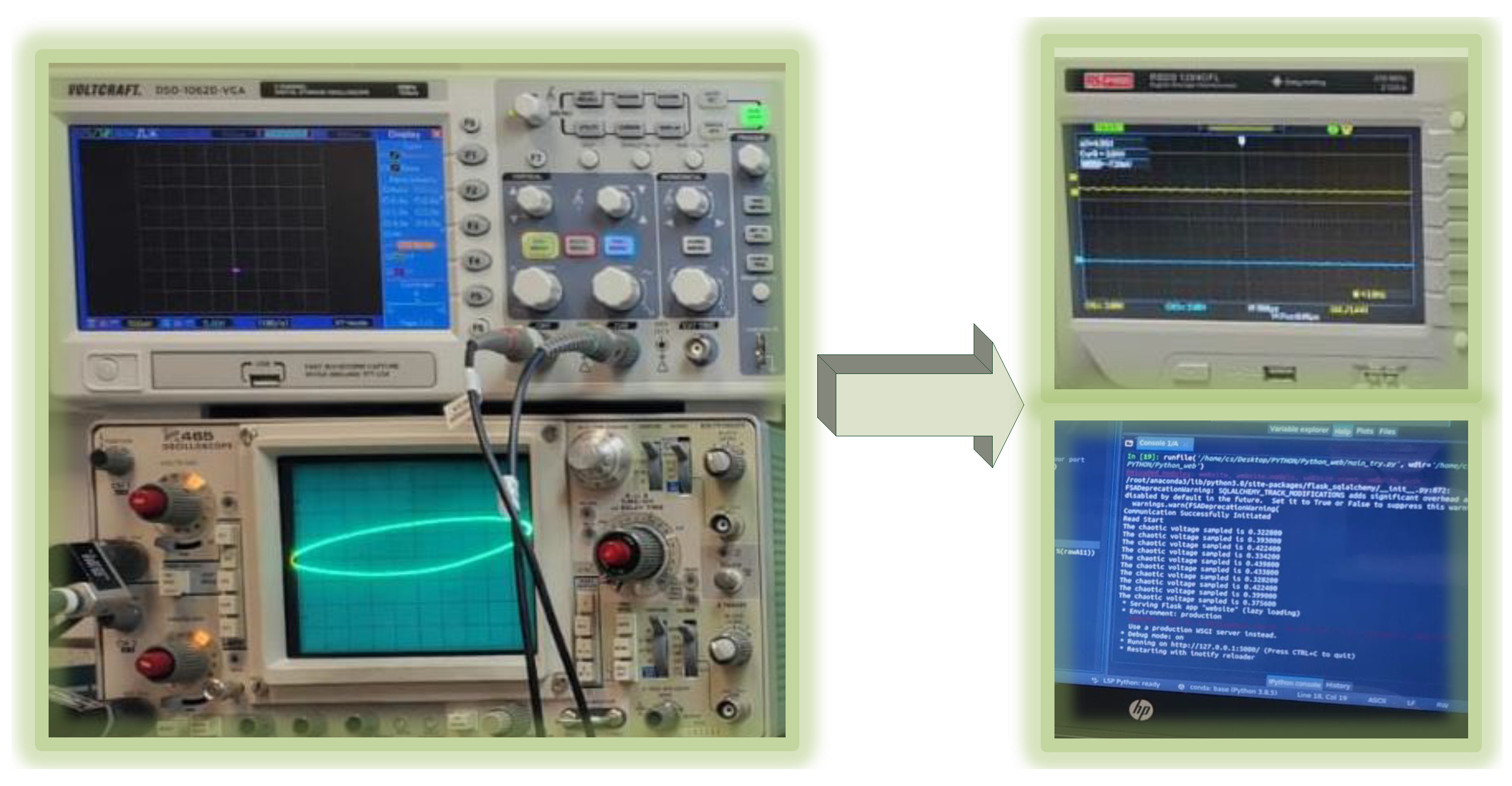
Moreover, we are adopting an equivalent memristor circuit rather than the real memristor. For the experimental part, a memristor Chua diode was used, which has a simpler implementation and thus easier manufacturing.Depending on the emulator, the waveform will have a different voltage range. In this way, the adaptor circuit of the WPT system can be adopted in any memristor emulator. Instead of using coils for the power transmission, the Shaffner 8 mH 2:1 transformer has been adopted. This transformer gives 4 mH mutual coupling. The significant test is the development of chaos in the circuits and the sampling with the Arduino board, which can create numbers. Measurements such as the power transferred and the distance are not significant, because the transmitter and the receiver are both active and the system is not transferring power over distance. The two circuits can generate multistability and have the same behaviour because they have the same circuit parameters and initial conditions. The two memristor-based circuits have the same dynamical behaviour, and they also have synchronisation in their phase portrait, as shown in the oscilloscopes in Figure 12. Before sampling, the top oscilloscope was connected to the transmitter, the bottom one to the receiver, and the side one to the waveform generated in the adopting circuit.On the side oscilloscope, there is a plot of the waveform of the voltages of the operational amplifier and the input voltage of the ADC (the voltage on capacitor ).
4.4. Arduino True Number Generation
Once the chaos has been generated, the voltage in the coil is adjusted and sampled. Chaotic voltage behaviour is the source of entropy. Therefore, it is possible to create a true random number generator (TRNG). True random number generators create sequences that are impossible to predict. They use random physical phenomena as their source of randomness. When the transmitter and receiver are out of range, there is no chaos and the numbers generated are near to zero. As shown in Figure 17, the transmitter of the bottom oscillator is continuously trying to find a receiver. The waveform sampled is only noise. After 20 readings (or more), the python code concludes that there is no chaos. When the transmitter and receiver are in synchronisation, there is a chaotic waveform to sample and obtain the TRNG, as shown in Figure 18. For safety reasons, it has been regulated to a maximum of 3. The values of the voltage obtained are true random numbers from the entropy of the chaotic circuit. Further improvement on the security analysis and mathematical functions or possible algorithms are out of the scope of this manuscript.
4.5. Statistical Tests
In order to analyse the data collected from the Arduino board and shown from the Python code, it is necessary to have this data normalised and converted into binary numbers through symbolic dynamics. More specifically, each signal is compared to a threshold, with a value of 1 assigned to the output bit if its value at the time n exceeds the threshold’s value, and 0 otherwise. The threshold for each of the two entropy sources has been set to the average of the state variable utilised, resulting in a uniform distribution of “0” and “1” symbols. There are several tests that may be used to evaluate the statistical characteristics of TRNGs.
Displaying the sequence as a bitmap graphic, with each pixel representing one bit, is the simplest and most straightforward approach to visually evaluate the randomness characteristic. This is the first test and it will be sufficient to indicate if there is anything clearly incorrect. As seen in Figure 19, the bitmap has no pattern and appears to be indistinguishable from white noise to the human eye, which was anticipated above.
In our application, we have used a package of the Linux Operating System called rngtest which works on blocks of 20,000 bits at a time (from stdin), using the Federal Information Processing Standard Publication (FIPS) 140-2 (the U.S. government’s computer security standard) tests to verify the randomness of the block of data [31]. Each block is put through five different tests: monobit, poker, runs, long run, and continuous run. The block fails the test if any of these fail. As a direct output, a natural source of random bits may not produce unbiased bits. Many applications, particularly in cryptography, rely on unbiased bit sequences. To recover unbiased bits from a faulty generator with unknown bias, there are several approaches, known as de-skewing or whitening algorithms.
After the de-skewing algorithm, we performed a variety of checks on byte sequences stored in files by utilising ent pseudorandom number sequence test in the Linux OS. The software may be used to test pseudorandom number generators for encryption and statistical sampling applications, compression techniques, and other applications that need to know how dense a file is. The test will be as follows:
Entropy. The amount of bits per character used to describe the information density of the file’s contents. The following findings, which came from analysing a JPEG-compressed picture file, show that the file is highly packed in information—basically random [32] (pp. 104–108). As a result, file compression is unlikely to lower the file’s size. The program’s C source code, on the other hand, has an entropy of around 4.9 bits per character, implying that optimum compression would reduce the file’s size by 38%.
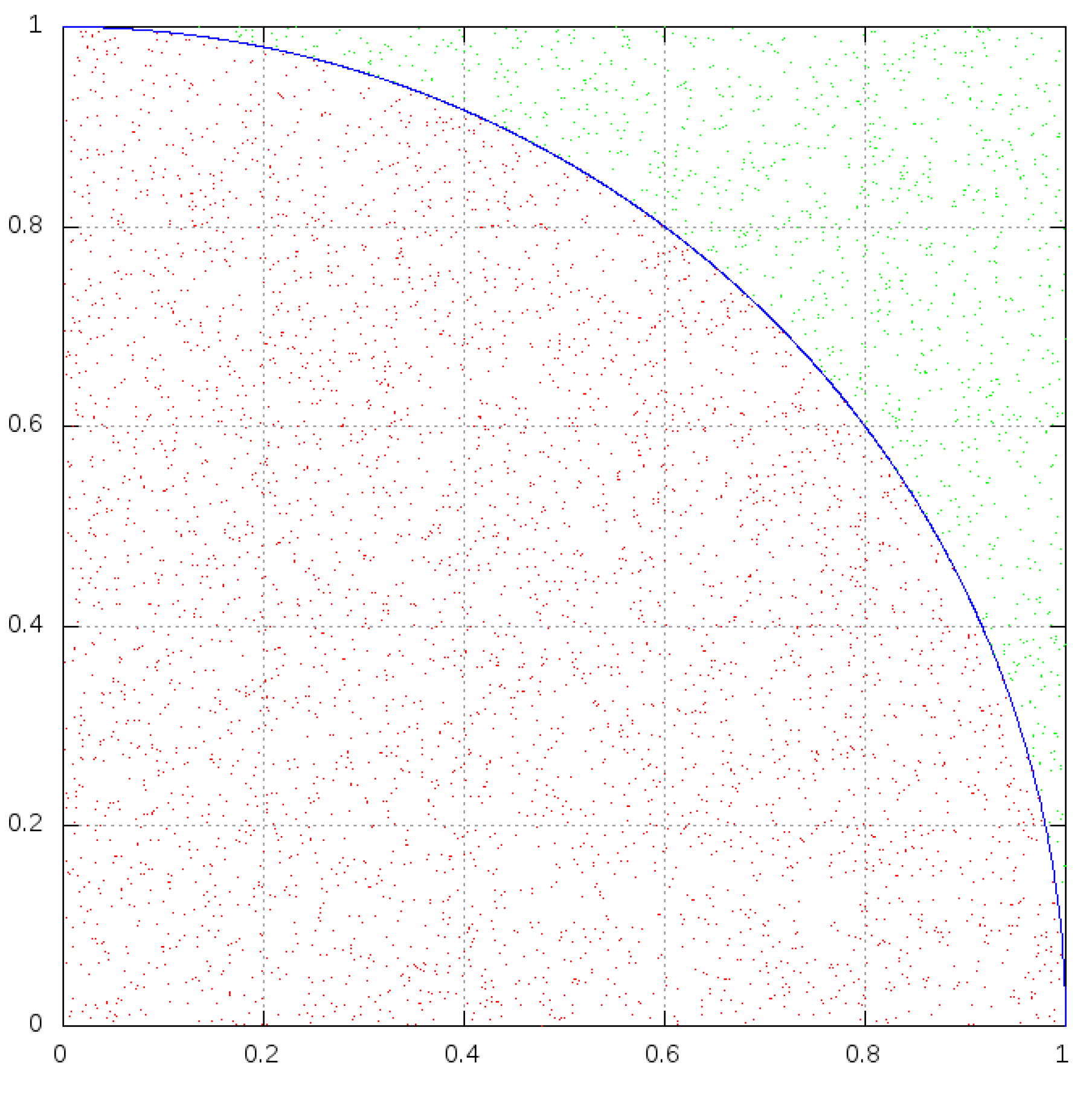
Monte Carlo. Evaluating the Monte Carlo test, as stated in [33], is another easy approach to test for randomness. Blocks of successive 48-bit numbers are used to produce (x, y) pairs, with each coordinate being a 24-bit integer. As shown in Figure 20, in a square (edge r) and inscribed a circle (radius r), the ratio, q, of the circle area in the first quadrant to the square area yields . Calculating , we can obtain the ratio q by extracting pairs of random points (x,y) from our sequence. We may estimate q by counting the number of points that fall inside the circle and dividing that number by the total number of points. If the sequence is near to random, the value calculated for will approach the correct value of for extremely long streams (this approximation converges very slowly).
Chi-Square. The chi-square test is the most widely used test for data unpredictability, and it is particularly sensitive to pseudorandom sequence generator mistakes. For the stream of bytes in the file, the chi-square distribution is computed and expressed as an absolute number and a percentage, indicating how often a genuinely random sequence would surpass the estimated value [34]. We interpret the percentage as the likelihood that the sequence being tested is not random [35] (pp. 30–35). The sequence is almost likely not random if the proportion is more than 99% or less than 1%. The sequence is suspicious if the proportion is between 99% and 95%, or between 1% and 5%. The sequence is “almost suspicious” if it has a percentage between 90% and 95% and a percentage between 5% and 10%.
Arithmetic mean. Summing all the bytes in the file and dividing by the file length yields this result. This should be around 127.5 if the data are close to random (0.5 for −b option output). The values are consistently high or low if the mean deviates from this value.
Serial correlation coefficient. This value indicates how much each byte in the file is dependent on the previous byte. This number (which might be positive or negative) will, of course, be close to zero for random sequences. The serial correlation coefficient of a non-random byte stream, such as a C-based programme, will be on the order of 0.5. Serial correlation coefficients for highly predictable data, such as uncompressed bitmaps, will approach 1, as it is further described in Reference [35] (pp. 64–65).
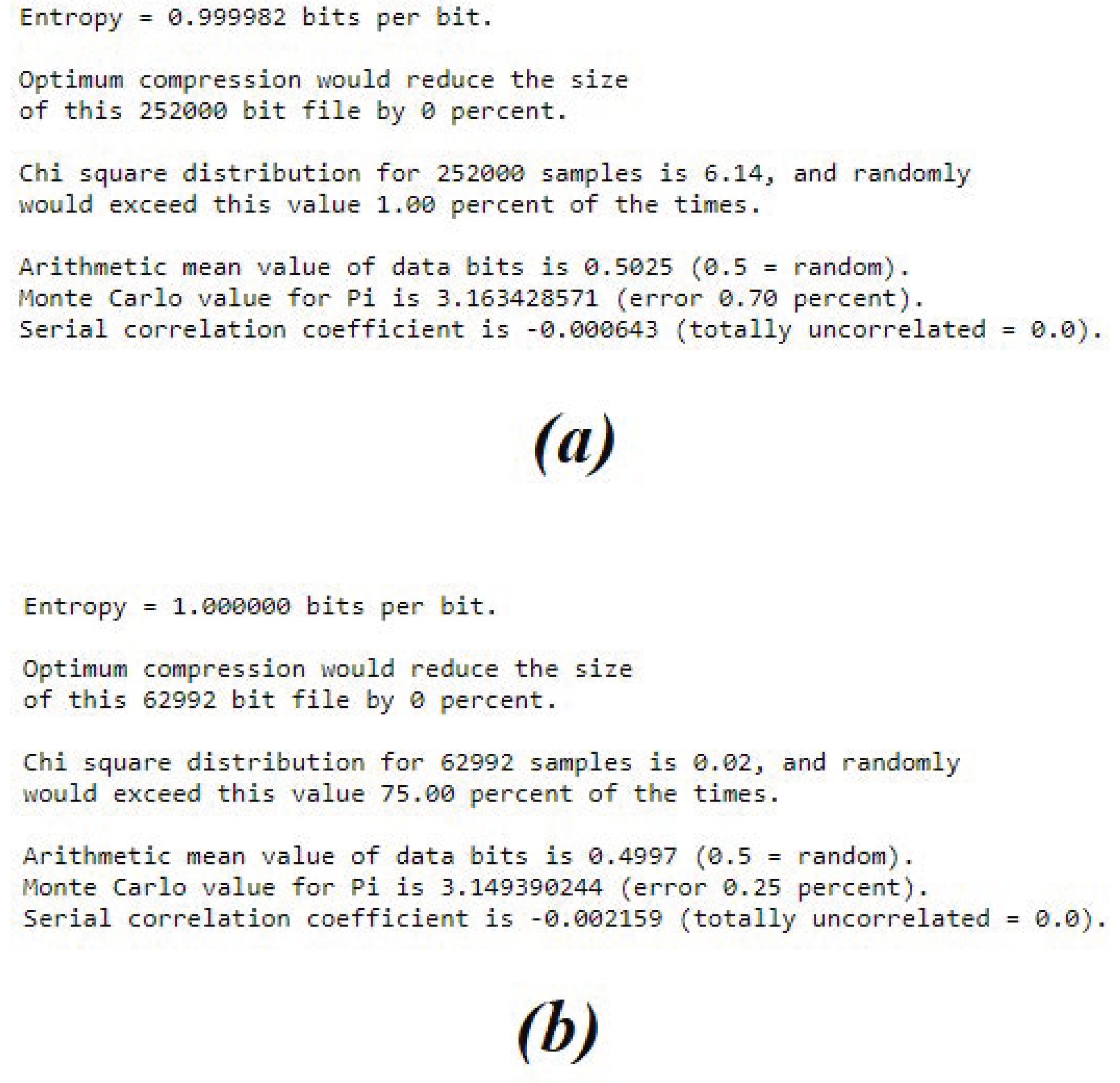
The statistical characteristics are consistent with what we would expect. Since after few hours as shown in Figure 21a, the entropy of the chaos is nearly on. After 56 h (nearly 3 days ) of no-stop operation and 250,000 bits out of the generator (after de-skewing), the test results are a really random sequence as shown in Figure 21b. The results confirm that our sequences are true random numbers.
5. Conclusions
Security on powering systems has a crucial role in all the electronic systems. This growing challenge is currently fulfilled with the extreme use of software and algorithms to encrypt and decrypt data. Unfortunately, once the type of algorithm is known, it is often hacked because it relies on the programming code. In this paper, a new circuit topology for inductive WPT using a memristive circuit has been introduced, whereas traditional WPT circuits are based on inverters in order to generate an oscillation for the transmitter coils.
Adopting switches, the system has intrinsic energy dissipation sources and requires an additional control circuit for the correct switching time. On the other hand, the memristor is able to create a chaotic oscillation without adopting switches. The oscillation makes the system transmit power and creates chaotic behaviour, which is advantageous for high security encryption. The functionality of the system has been verified by electronic simulation and an experiment. The statistical tests are consistent and confirm that our sequences are true random numbers.
Further improvements will be performed by increasing the type of the coils and the application for the TRNG.
Author Contributions
Conceptualization, C.S.K.; methodology, C.S.K.; software, C.S.K.; validation, and J.C.; formal analysis, C.S.K.; investigation, C.S.K.; resources, C.S.K.; data curation, C.S.K.; writing–original draft preparation, C.S.K.; writing–review and editing, M.A.; visualization, Q.X.; supervision, Y.H.; project administration, C.S.K.; funding acquisition, C.S.K. All authors have read and agreed to the published version of the manuscript.
Funding
This research received no external funding.
Data Availability Statement
No data avaibility.
Conflicts of Interest
The authors declare no conflict of interest.
References
- Wei, X.; Wang, Z.; Dai, H. A critical review of wireless power transfer via strongly coupled magnetic resonances. Energies 2014, 7, 4316–4341. [Google Scholar] [CrossRef] [Green Version]
- Abou Houran, M.; Yang, X.; Chen, W. Magnetically coupled resonance WPT: Review of compensation topologies, resonator structures with misalignment, and EMI diagnostics. Electronics 2018, 7, 296. [Google Scholar] [CrossRef] [Green Version]
- Kuka, S.; Ni, K.; Alkahtani, M. A Review of Methods and Challenges for Improvement in Efficiency and Distance for Wireless Power Transfer Applications. Power Electron. Drives 2019, 5, 1–25. [Google Scholar] [CrossRef]
- Hou, J.; Chen, Q.; Wong, S.C.; Chi, K.T.; Ruan, X. Analysis and control of series/series-parallel compensated resonant converter for contactless power transfer. IEEE J. Emerg. Sel. Top. Power Electron. 2014, 3, 124–136. [Google Scholar]
- Miller, J.M.; Onar, O.C.; Chinthavali, M. Primary-side power flow control of wireless power transfer for electric vehicle charging. IEEE J. Emerg. Sel. Top. Power Electron. 2014, 3, 147–162. [Google Scholar] [CrossRef]
- Diekhans, T.; De Doncker, R.W. A dual-side controlled inductive power transfer system optimized for large coupling factor variations and partial load. IEEE Trans. Power Electron. 2015, 30, 6320–6328. [Google Scholar] [CrossRef]
- Wu, J.; Zhao, C.; Lin, Z.; Du, J.; Hu, Y.; He, X. Wireless Power and Data Transfer via a Common Inductive Link Using Frequency Division Multiplexing. IEEE Trans. Ind. Electron. 2015, 62, 7810–7820. [Google Scholar] [CrossRef] [Green Version]
- Zhang, Z.; Chau, K.; Liu, C.; Qiu, C.; Lin, F. An efficient wireless power transfer system with security considerations for electric vehicle applications. J. Appl. Phys. 2014, 115, 17A328. [Google Scholar] [CrossRef] [Green Version]
- Zhang, Y.; Lu, T.; Zhao, Z.; He, F.; Chen, K.; Yuan, L. Selective Wireless Power Transfer to Multiple Loads Using Receivers of Different Resonant Frequencies. IEEE Trans. Power Electron. 2015, 30, 6001–6005. [Google Scholar] [CrossRef]
- Chua, L.O.; Kang, S.M. Memristive devices and systems. Proc. IEEE 1976, 64, 209–223. [Google Scholar] [CrossRef]
- Stanley Williams, R. How we found the missing memristor. In Chaos, CNN, Memristors and Beyond: A Festschrift for Leon Chua with DVD-ROM, Composed by Eleonora Bilotta; World Scientific: Singapore, 2013; pp. 483–489. [Google Scholar]
- Vaidyanathan, S.; Volos, C. Advances in Memristors, Memristive Devices and Systems; Springer: Berlin/Heidelberg, Germany, 2017; Volume 701. [Google Scholar]
- Bao, B.; Jiang, T.; Xu, Q.; Chen, M.; Wu, H.; Hu, Y. Coexisting infinitely many attractors in active band-pass filter-based memristive circuit. Nonlinear Dyn. 2016, 86, 1711–1723. [Google Scholar] [CrossRef]
- Iu, H.H.C.; Yu, D.S.; Fitch, A.L.; Sreeram, V.; Chen, H. Controlling Chaos in a Memristor Based Circuit Using a Twin-T Notch Filter. IEEE Trans. Circuits Syst. I Regul. Pap. 2011, 58, 1337–1344. [Google Scholar] [CrossRef]
- Xu, Q.; Lin, Y.; Bao, B.; Chen, M. Multiple attractors in a non-ideal active voltage-controlled memristor based Chua’s circuit. Chaos, Solitons Fractals 2016, 83, 186–200. [Google Scholar] [CrossRef]
- Bao, H.; Wang, N.; Wu, H.; Song, Z.; Bao, B. Bi-stability in an improved memristor-based third-order Wien-bridge oscillator. IETE Tech. Rev. 2019, 36, 109–116. [Google Scholar] [CrossRef]
- Bao, B.; Bao, H.; Wang, N.; Chen, M.; Xu, Q. Hidden extreme multistability in memristive hyperchaotic system. Chaos Solitons Fractals 2017, 94, 102–111. [Google Scholar] [CrossRef]
- Bao, H.; Wang, N.; Bao, B.; Chen, M.; Jin, P.; Wang, G. Initial condition-dependent dynamics and transient period in memristor-based hypogenetic jerk system with four line equilibria. Commun. Nonlinear Sci. Numer. Simul. 2018, 57, 264–275. [Google Scholar] [CrossRef]
- Chen, M.; Yu, J.; Bao, B. Finding hidden attractors in improved memristor-based Chua’s circuit. Electron. Lett. 2015, 51, 462–464. [Google Scholar] [CrossRef]
- Hameed, S.; Hameed, B.; Hussain, S.A.; Khalid, W. Lightweight Security Middleware to Detect Malicious Content in NFC Tags or Smart Posters. In Proceedings of the 2014 IEEE 13th International Conference on Trust, Security and Privacy in Computing and Communications, Beijing, China, 24–26 September 2014; pp. 900–905. [Google Scholar] [CrossRef]
- Zhuang, Z.; Zhang, J.; Geng, W. Analysis and Optimization to an NFC Security Authentication Algorithm Based on Hash Functions. In Proceedings of the 2014 International Conference on Wireless Communication and Sensor Network, Wuhan, China, 13–14 December 2014; pp. 240–245. [Google Scholar] [CrossRef]
- Chattha, N.A. NFC—Vulnerabilities and defense. In Proceedings of the 2014 Conference on Information Assurance and Cyber Security (CIACS), Rawalpindi, Pakistan, 12–13 June 2014; pp. 35–38. [Google Scholar] [CrossRef]
- Aliexpress. NFC Door Lock. Available online: http://aliexpress.com (accessed on 30 June 2021).
- Li, W.; Yang, X. A Parallel and Reconfigurable United Architecture for Fibonacci and Galois LFSR. In Proceedings of the 2015 7th International Conference on Intelligent Human-Machine Systems and Cybernetics, Hangzhou, China, 22–23 August 2015; Volume 1, pp. 203–206. [Google Scholar] [CrossRef]
- Essaid, M.; Akharraz, I.; Saaidi, A.; Mouhib, A. A New Image Encryption Scheme Based on Confusion-Diffusion Using an Enhanced Skew Tent Map. Procedia Comput. Sci. 2018, 127, 539–548. [Google Scholar] [CrossRef]
- Bagini, V.; Bucci, M. A Design of Reliable True Random Number Generator for Cryptographic Applications. In Cryptographic Hardware and Embedded Systems; Koç, Ç.K., Paar, C., Eds.; Springer: Berlin/Heidelberg, Germany, 1999; pp. 204–218. [Google Scholar]
- Chen, W.; Che, W.; Yan, N.; Tan, X.; Min, H. Ultra-low power truly random number generator for RFID tag. Wirel. Pers. Commun. 2011, 59, 85–94. [Google Scholar] [CrossRef]
- Abunahla, H.; Shehada, D.; Yeun, C.Y.; OKelly, C.J.; Jaoude, M.A.; Mohammad, B. Novel microscale memristor with uniqueness property for securing communications. In Proceedings of the 2016 IEEE 59th International Midwest Symposium on Circuits and Systems (MWSCAS), Abu Dhabi, United Arab Emirates, 16–19 October 2016; pp. 1–4. [Google Scholar] [CrossRef]
- Yang, F.; Mou, J.; Sun, K.; Cao, Y.; Jin, J. Color Image Compression-Encryption Algorithm Based on Fractional-Order Memristor Chaotic Circuit. IEEE Access 2019, 7, 58751–58763. [Google Scholar] [CrossRef]
- Wolf, A.; Swift, J.B.; Swinney, H.L.; Vastano, J.A. Determining Lyapunov exponents from a time series. Phys. D Nonlinear Phenom. 1985, 16, 285–317. [Google Scholar] [CrossRef] [Green Version]
- Publication, F.I.P.S. Security Requirements for Cryptographic Modules. Available online: https://nvlpubs.nist.gov/nistpubs/FIPS/NIST.FIPS.140-2.pdf (accessed on 30 June 2021).
- Hamming, R.W. Coding and Information Theory; Prentice-Hall, Inc.: Hoboken, NJ, USA, 1986; pp. 104–108. [Google Scholar]
- Howes, L.; Thomas, D. Chapter 37. Efficient Random Number Generation and Application Using CUDA. Available online: https://developer.nvidia.com/gpugems/gpugems3/part-vi-gpu-computing/chapter-37-efficient-random-number-generation-and-application (accessed on 30 June 2021).
- Walker, J. Chi-Square Calculator. Available online: http://www.fourmilab.ch/rpkp/experiments/analysis/chiCalc.html (accessed on 30 June 2021).
- Knuth, D.E. Art of Computer Programming, Volume 2: Seminumerical Algorithms; Addison-Wesley Professional: Reading, MA, USA, 2014; pp. 35–65. [Google Scholar]
Figure 1.
Memsistive circuit developed by L. Chua [10].
Figure 1.
Memsistive circuit developed by L. Chua [10].

Figure 2.
Non-ideal active voltage-controlled memristor equivalent realisation. This circuit is active and only has charge storing qualities.
Figure 2.
Non-ideal active voltage-controlled memristor equivalent realisation. This circuit is active and only has charge storing qualities.

Figure 3.
Some security applications of NFC technology. Commercial products of a security safe lock with a NFC system opening key. A BMW door opening and NFC house handle. Image collected from a car shop in UK and web source [23].
Figure 3.
Some security applications of NFC technology. Commercial products of a security safe lock with a NFC system opening key. A BMW door opening and NFC house handle. Image collected from a car shop in UK and web source [23].

Figure 4.
The cryptosystem model applied in high-level security: on the left, the transmitter lock and the receiver in the Card Key.
Figure 4.
The cryptosystem model applied in high-level security: on the left, the transmitter lock and the receiver in the Card Key.

Figure 5.
The wireless power transfer circuit and the system built with memristors.

Figure 6.
Flowchart of the door opening procedure.

Figure 7.
The figure shows the operating point (OP) of the system, the coupling value and the total inductance.
Figure 7.
The figure shows the operating point (OP) of the system, the coupling value and the total inductance.

Figure 8.
(a) Transmitter coil caved in the core in order to increase directionality. (b) Receiver coil and flat core to enhance energy harvesting.
Figure 8.
(a) Transmitter coil caved in the core in order to increase directionality. (b) Receiver coil and flat core to enhance energy harvesting.

Figure 9.
(a) Magnetic field intensity H spread in the air, where it can be seen as the vast green color (0 dB). (b) Magnetic field vector B spread in the air, where it can be seen as the vast green color (0 dB).
Figure 9.
(a) Magnetic field intensity H spread in the air, where it can be seen as the vast green color (0 dB). (b) Magnetic field vector B spread in the air, where it can be seen as the vast green color (0 dB).

Figure 10.
The power transmitted has a significant chaotic behaviour and usually a value lower than 0.2 mW.
Figure 10.
The power transmitted has a significant chaotic behaviour and usually a value lower than 0.2 mW.

Figure 11.
(a) Transmitter voltage behaviour (blue) and (b) receiver (purple) in the coil.

Figure 12.
The behaviour in the transmitter (Chua circuit) is a well-known double-attractor phase portrait. This plot is the characteristic of the voltage in the receiver coil (inductor and compensation capacitor)—voltage on the receiver memristor.
Figure 12.
The behaviour in the transmitter (Chua circuit) is a well-known double-attractor phase portrait. This plot is the characteristic of the voltage in the receiver coil (inductor and compensation capacitor)—voltage on the receiver memristor.

Figure 13.
Time step of the chaotic behaviour when the receiver is disconnected (highlighted in yellow): the LC voltage and memristor voltage in receiver and transmitter, in purple and green, respectively. At the disconnection (in the 3rd graph), the receiver memristor holds its last status as shown in the 4th graph in blue.

Figure 14.
Data transmission at 3Kbps; it is possible to notice the time of switching (highlighted in yellow) of the chaotic behaviour in the LC, the memristor voltage and the internal status in the 4th graph.
Figure 14.
Data transmission at 3Kbps; it is possible to notice the time of switching (highlighted in yellow) of the chaotic behaviour in the LC, the memristor voltage and the internal status in the 4th graph.

Figure 15.
The schematic of the memristor wireless power transfer circuit and the adaptive circuit for the TRNG in the laptop.
Figure 15.
The schematic of the memristor wireless power transfer circuit and the adaptive circuit for the TRNG in the laptop.

Figure 16.
The real experiment with a real time TRNG.

Figure 17.
No chaotic waveform will generate near to zero random numbers. On the left is the XY plot of the transmitter (bottom) and receiver (top). On the right is the ADC input voltage and the execution of the Python code with number generation.
Figure 17.
No chaotic waveform will generate near to zero random numbers. On the left is the XY plot of the transmitter (bottom) and receiver (top). On the right is the ADC input voltage and the execution of the Python code with number generation.

Figure 18.
A chaotic waveform will generate true random numbers. On the left is the XY plot of the transmitter (bottom) and receiver (top). On the right is the ADC input voltage and the execution of the Python code with number generation.
Figure 18.
A chaotic waveform will generate true random numbers. On the left is the XY plot of the transmitter (bottom) and receiver (top). On the right is the ADC input voltage and the execution of the Python code with number generation.

Figure 19.
The bitmap generated form the sequence of numbers sampled, which has no pattern and appears to be indistinguishable from white noise to the human eye.
Figure 19.
The bitmap generated form the sequence of numbers sampled, which has no pattern and appears to be indistinguishable from white noise to the human eye.

Figure 20.
Monte Carlo test; blocks of successive 48-bit numbers are used to produce (x,y) pairs, with each coordinate being a 24-bit integer.
Figure 20.
Monte Carlo test; blocks of successive 48-bit numbers are used to produce (x,y) pairs, with each coordinate being a 24-bit integer.

Figure 21.
The ent give us the results of five different tests. The test results after (a) two hours and (b) more than 2 days results confirm that our sequences are true random numbers.
Figure 21.
The ent give us the results of five different tests. The test results after (a) two hours and (b) more than 2 days results confirm that our sequences are true random numbers.


Table 1.
Comparison between traditional WPT and an M-WPT system.
| WTP (NFC) | M-WPT | |
|---|---|---|
| Power | Transmitted (Harvested) | Harvested |
| Data | Oscillation | Chaos |
| Distance | Over 30 cm (10 cm) | 10 cm |
| Operating Frequency | Up to 13.5 MHz | Up to 7 KHz |
| Control | Timing, Switches and Data Algorithm | Data |
| Receivers | Many | Only one |
Table 2.
Memristor model internal values.
| Memristor Equivalent | |||
|---|---|---|---|
| Parameter | Value | Parameter | Value |
| 4 k | 2 k | ||
| 10 k | 1 nF | ||
| 1.4 k | 1 | ||
| 2 k | 0.1 | ||
Table 3.
Parameters of the system proposed.
| Chua’s Parameter | Transmitter | Receiver | Value |
|---|---|---|---|
| 6.8 nF | |||
| 68 nF | |||
| 2.18 k | |||
| L | 8 mH | ||
| M | 3.8 mH |
Publisher’s Note: MDPI stays neutral with regard to jurisdictional claims in published maps and institutional affiliations. |
© 2021 by the authors. Licensee MDPI, Basel, Switzerland. This article is an open access article distributed under the terms and conditions of the Creative Commons Attribution (CC BY) license (https://creativecommons.org/licenses/by/4.0/).
Share and Cite
MDPI and ACS Style
Kuka, C.S.; Hu, Y.; Xu, Q.; Chandler, J.; Alkahtani, M. A Novel True Random Number Generator in Near Field Communication as Memristive Wireless Power Transmission. J 2021, 4, 764-783. https://doi.org/10.3390/j4040052
AMA Style
Kuka CS, Hu Y, Xu Q, Chandler J, Alkahtani M. A Novel True Random Number Generator in Near Field Communication as Memristive Wireless Power Transmission. J. 2021; 4(4):764-783. https://doi.org/10.3390/j4040052
Chicago/Turabian StyleKuka, Colin Sokol, Yihua Hu, Quan Xu, James Chandler, and Mohammed Alkahtani. 2021. "A Novel True Random Number Generator in Near Field Communication as Memristive Wireless Power Transmission" J 4, no. 4: 764-783. https://doi.org/10.3390/j4040052