1. Introduction
Energy harvesting from environment energy sources has become a vibrant study field and attracted huge attention in recent years due to numerous applications. Powering wireless electronics and sensors with very low electrical power requirements at the location without the limitations of batteries is pleasing for various automation and monitoring systems. Consequently, energy harvesters are designed to transform the ambient energy into a usable power form to supply the small wireless systems throughout their lifespan.
Recently, vibration-based energy harvesting has become more appealing and has received further attention. The three mechanical conversion mechanisms of vibration energy to electrical energy are: electrostatic, electromagnetic, and piezoelectric [
1]. The small dimension, custom shape fabrication capability, and great power conversion potential are the major benefits of the piezoelectric methodology for vibration-based energy harvesting [
2]. Even a minor external excitation results in significant amount of produced voltage without demanding any low-efficient initiation mechanical mechanism [
3]. The principal characteristic of piezoelectric materials is to generate electrical charge from an external mechanical stimulation (direct effect) and to sense deformation from an applied external electrical polarization (reverse effect). The direct piezoelectric effect is good for harvesting environment energy and transforming it to electrical energy to supply smart systems.
There are quite a few literature reviews on piezoelectric harvesters with abundant suggested methodologies and designs [
4,
5,
6,
7]. The most common design is the transversely vibrating cantilever beam with surface bonded piezoelectric layers which has a simple and cost-efficient configuration. They mostly function on the resonance mechanism to increase the strain distribution in the piezoelectric layer and ultimately raise the electrical power output. Moreover, geometry refinement of the harvester itself is a key advancement area. Roundy et al. [
8] pointed that a trapezoidal geometry can distribute the strain consistently to attain the maximum strain at every point in the piezoelectric energy harvester. They have indicated that a harvester with a trapezoidal profile can produce more than twice the energy compared to a rectangular harvester. Thus, they recommended a trapezoidal shape harvester with wider cross-section, smaller size, and lower weight. Baker et al. [
9] showed up to 50% greater generated power by using a cantilever piezoelectric harvester with trapezoidal profile. Additionally, Xie et al. [
10] reported 70 times larger power output than the uniform configuration by using a linearly tapered bimorph energy harvester. Recently, Keshmiri et al. [
11] presented a theoretical model for piezoelectric energy harvesters with nonlinearly tapered geometry and functionally graded material properties. Based on their model, up to 20 times higher output voltage can be obtained.
One of the biggest drawbacks of the common vibration energy harvesters is the very limited practical bandwidths over which energy can be hunted. In order to increase the frequency range of energy harvesters, two approaches of tuning the resonant frequency and widening the bandwidth are suggested in the literature [
12]. Based on the widen bandwidth method, the operational frequency range of the vibration energy generator can be expanded by using an array of harvesters with different natural frequencies. In other words, the piezoelectric energy harvester should have the appropriate bandwidth in the range of peak-power frequencies of the ambient vibrations which can be easily measured in different environments. As one of the pioneers works in this area, Shahruz [
13] used an ensemble of cantilever beams with proof mass to build a mechanical bandpass filter and showed a systematic procedure for designing energy harvesters which can efficiently harvest energy from a variety of vibration sources with various peak-power frequencies. He has called the proposed device a mechanical bandpass filter. Moreover, several other researchers have benefited from a similar configuration to design a wideband energy harvester as well [
14,
15,
16]. Hajati and Kim [
17,
18] designed and tested a novel pie-shaped piezoelectric energy harvester which harvests energy from parasitic environment vibrations with a wide range of amplitude and frequency. Their design utilizes the tensile stretching strain in beams that enables wideband resonance and robust power generation. Yang and Zu [
19] developed an energy harvester working in the compressive mode. Their multi-stage force amplification mechanism has considerably increased the electrical outputs and bandwidth. More recently, Li et al. [
20] investigated an interdigital-shaped oscillator including a rectangular flexible frame and groups of cantilever beams interdigitally attached to reach low frequency and wide-bandwidth energy harvesting. Based on their designed device, they have reported a 460% increase in bandwidth below 80 Hz and achieved maximum open-circuit voltage and power of 65 V and 4.5 mW, respectively.
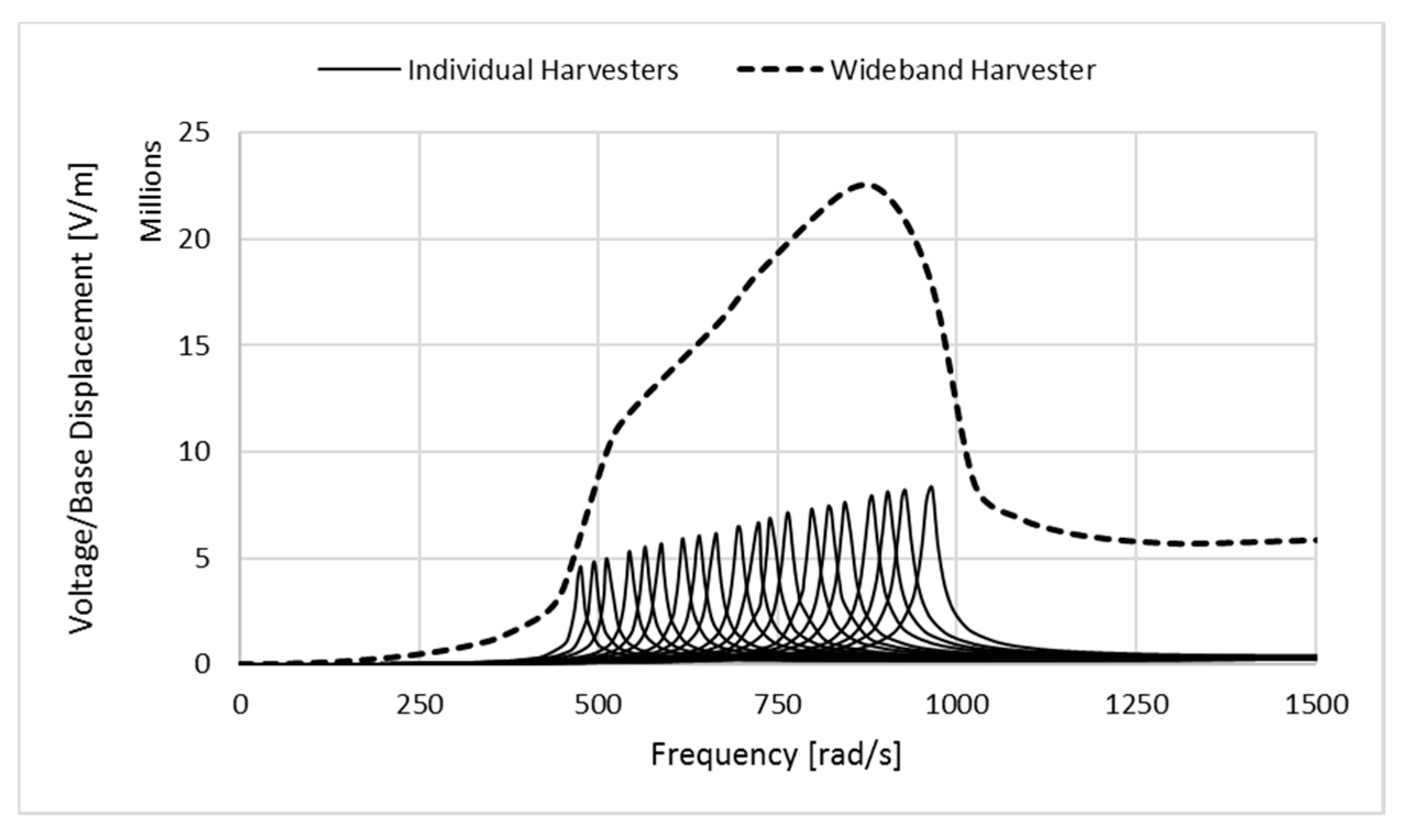
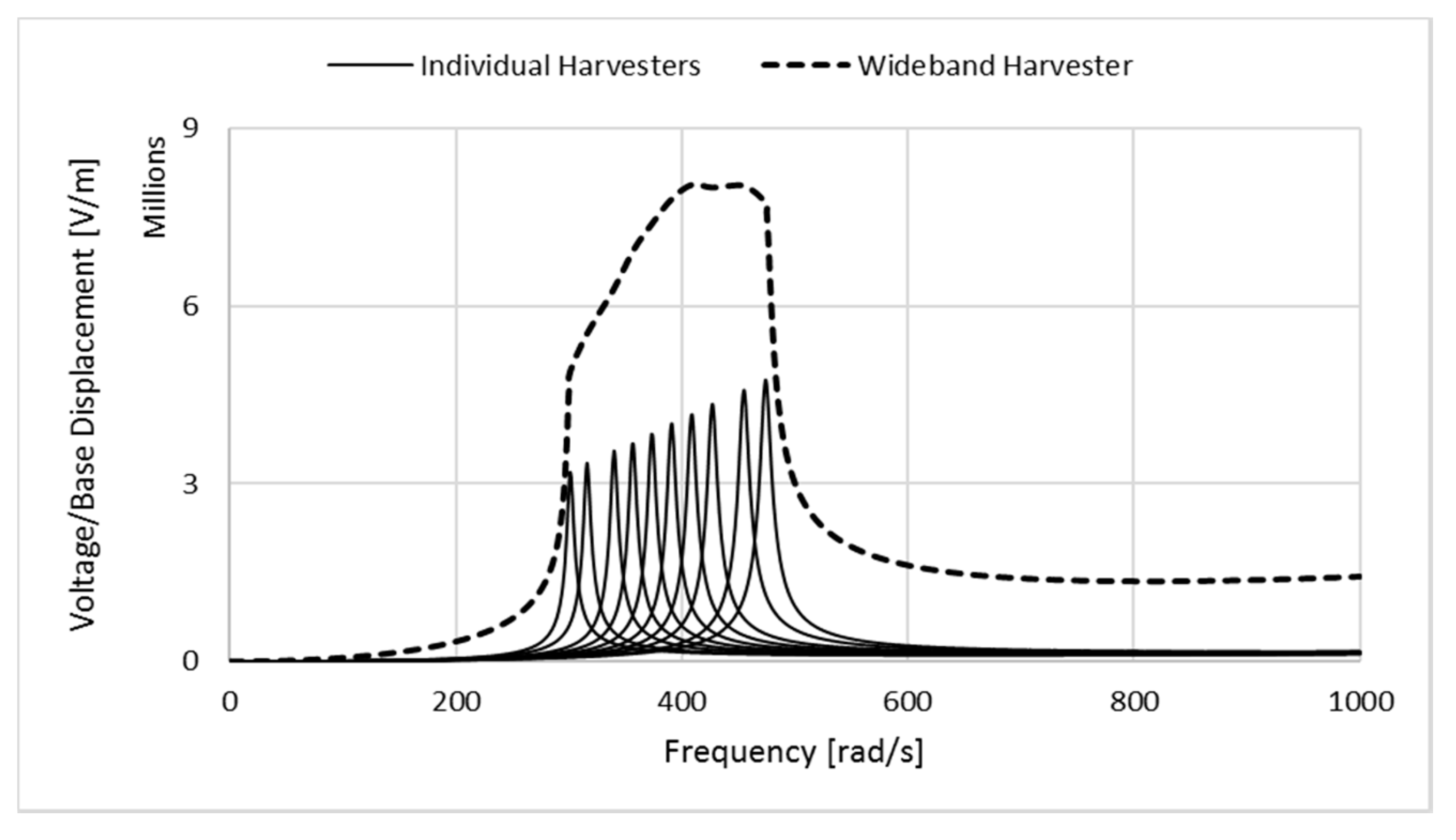
This work investigates the new design and theoretical development of a wideband piezoelectric energy harvesting system with efficient electromechanical outputs. The current study endeavors to challenge earlier energy harvesting designs and engineer a novel and advanced energy harvester system with adequate bandwidth in the range of ambient vibration frequencies by considering nonlinear geometry design. The steady-state dynamic solution of the harmonic base excitation problem for lateral vibration of a single nonlinearly tapered piezoelectric-coupled cantilever beam with strain rate damping is presented and electromechanical outputs are analytically derived and compared with the traditional uniform design. The wideband harvester is then proposed by combining non-uniform piezoelectric-coupled cantilevers with different taper ratios. The mathematical model is developed based on Adomian decomposition method (ADM) and the mechanical model is applicable to any slender beam which allows neglecting shear deformation and rotatory inertia effects. The proposed approach is numerically tested with two sample structures made of 20 and 10 non-uniform piezoelectric-coupled cantilevers with different geometries, but it can be generalized to various numbers of beams and different conversion principles.
2. Materials and Methods
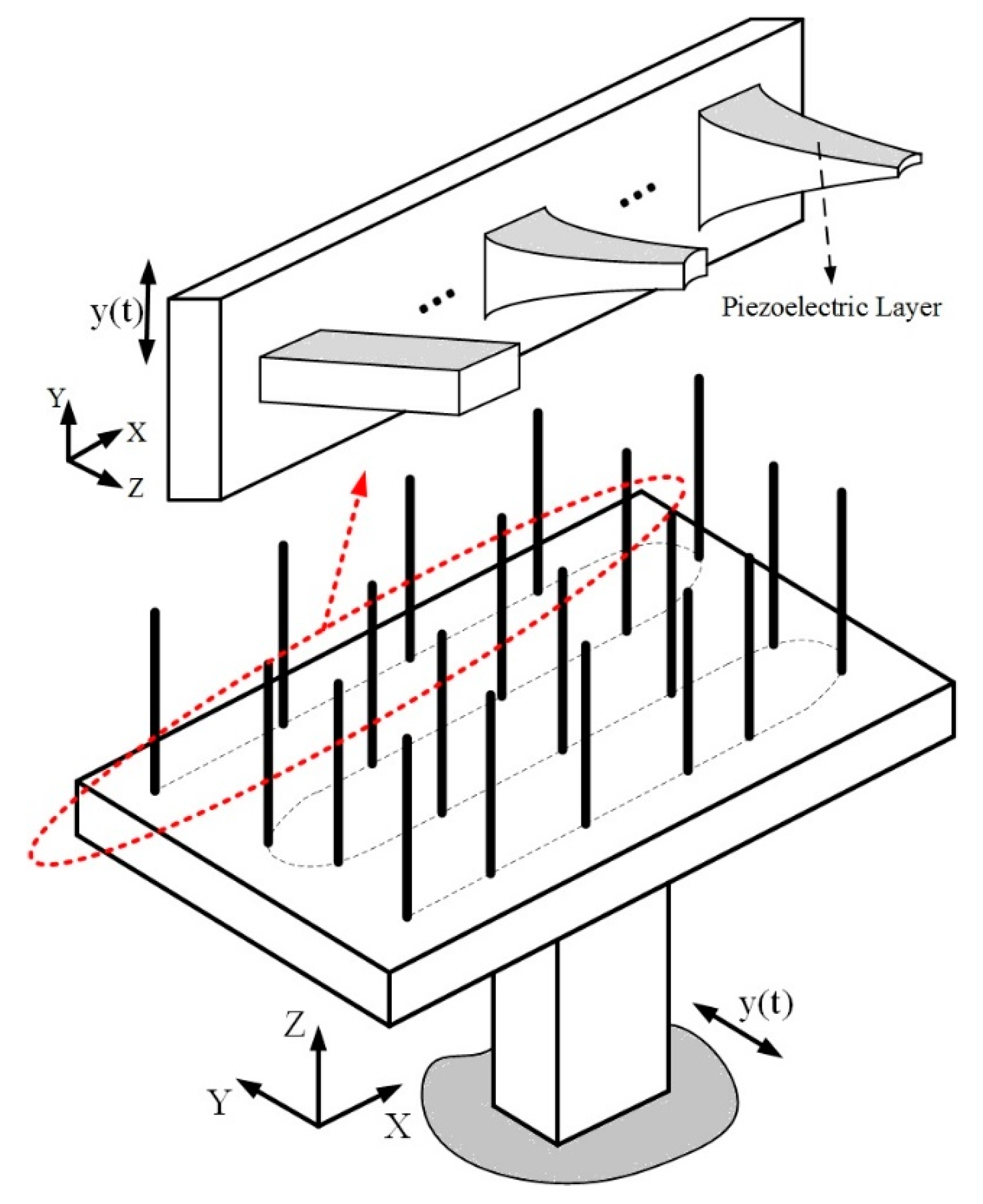
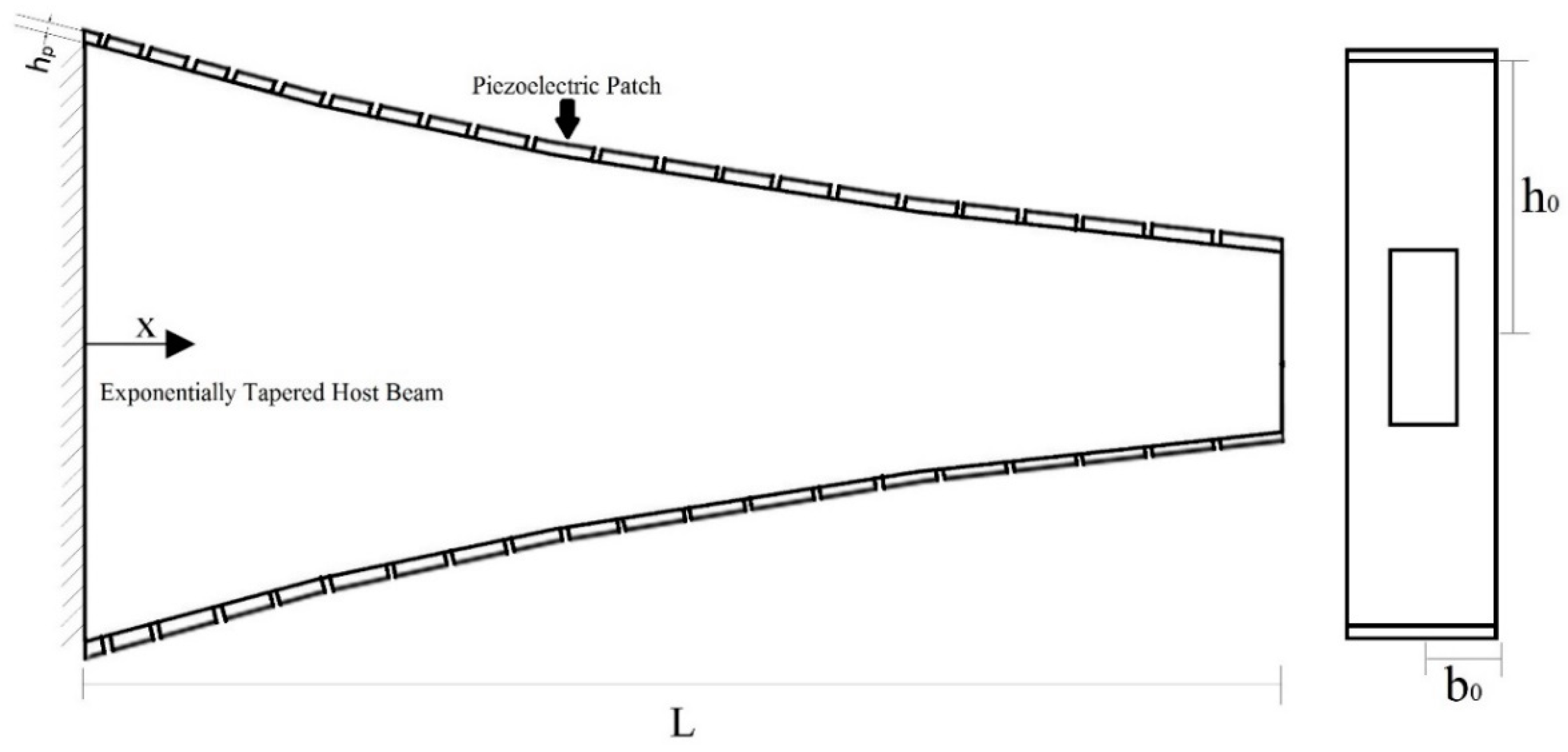
The proposed bimorph piezoelectric energy harvester includes beams with general geometry configuration with piezoelectric patches bonded on the top and bottom surfaces,
Figure 1.
L is the length of the beam, 2b0 is the width of the beam at the fixed end, 2h0 is the thickness of the beam at the fixed end, and hp is the thickness of the piezoelectric layer.
y(
t) =
Ye
jφt is defined as the harmonic base motion excitation, where
Y is the amplitude of the base displacement,
φ is the angular frequency of the harmonic excitation, and
j is the unit imaginary number. The dynamic governing equation of the lateral vibration under base motion for a piezoelectric coupled beam with non-uniform geometry and structural strain rate damping can be expressed by,
where
x is position variable along length of the beam,
t is time variable, 𝜌 is the equivalent mass density,
A(
x) is cross-sectional area,
w(
x,
t) is the deflection function,
E is the equivalent elasticity modulus,
I(
x) is the second moment of area, and
Cs is the strain rate damping coefficient. Moreover, boundary conditions for the non-uniform cantilever beam are defined as,
By using the normal mode analysis for a linear system, the solution of Equation (1) is supposed to be a linear combination of the vibration solutions corresponding to normal modes of the beam,
where
Xi(
x) are mass normalized eigenfunctions and
Ti(
t) are modal participation coefficients for the
ith vibration mode. Since the system is proportionally damped, eigenfunctions represented by
Xi(
x) are normal mode eigenfunctions of the corresponding undamped free vibration problem [
21,
22]. By inserting Equation (3) into the governing equation of the problem, Equation (1), normal modes can be calculated by solving,
where 𝜔
i2 are the undamped natural frequencies of the structure.
Now, ADM is employed to solve the Equation (4). ADM is an operative technique obtaining analytical solution of vibrational systems without linearization or nonlinearity assumptions. Hence, it is physically more precise and realistic. The solution presented by ADM is an infinite series; an
n-term approximation which often works as a practical answer. An exact solution could be found with very small values of
n [
23]. For numerical purposes, the response can be improved by adding more terms which would be the exact solution of the problem if it exists [
24]. Details of the mathematical model have been completely discussed in [
23,
25]. By applying ADM and replacing the decomposition form of
X(
x), the mode shape function in the recurrence format is expressed as,
where the inverse operator
Lx−1 is a fourfold integration with respect to
x. Additionally,
C1 to
C4 are constants which should be evaluated from the system boundary conditions. As a result, all
Xk components are calculated.
Clearly, normal mode eigenfunctions satisfy the orthogonality conditions,
Therefore, the modal participation coefficients
Ti(
t) are the solution of the ordinary differential equation,
where 2ξ
i𝜔
i = Cs𝜔
i2/
E and ξ
i is the structural strain rate damping ratio of
ith vibration mode. Finally, the vibration response can be obtained by Duhamel integral,
where 𝜔
di is the
ith mode damped natural frequency. However, the steady state solution of Equation (7) is expressed as,
As a result, normal mode eigenfunctions in Equation (5) and modal participation coefficients in Equation (9) are used in Equation (3) to derive the dynamic steady-state response of the smart structure relative to its base as,
In order to find the electromechanical responses of the piezoelectric coupled beam in an open-circuit condition, the Erturk and Inman [
21] method is used here. The constitutive relation for piezoelectric materials is,
where
D3 is the electrical displacement,
d31 (Coulomb/N or m/V) is the piezoelectric coefficient with polarization in direction 3 due to the external stress in direction 1, 𝜎
1 is the axial stress along 1-axis,
e33𝜎 is the permittivity at constant stress, and
E3 is the electrical field along 3-axis. It should be noted that 1, 2, and 3 directions are aligned with
x,
y, and
z axes, respectively.
By replacing the axial stress 𝜎
1 with bending strain 𝜀
1, changing the component permittivity at constant stress into constant strain [
26] and knowing that due to assumed uniform electric field
E3(
t) =
V(
t)/
hp, Equation (11) can be rewritten as,
where
Ep is the piezoelectric elasticity modulus and
V(
t) is the electric voltage over the piezoelectric area. Furthermore, the longitudinal bending strain 𝜀
1(
x,
t) in the structure can be calculated as,
where
hc is the distance between the center of the piezoelectric layer and the beam’s neutral axis. Consequently, the electric displacement becomes,
The electric displacement D3(x,t) is related to the output electric charge q(t) by integration over the electrode area as,
It is noted that the piezoelectric layers should cover the whole surface of the beam. Since the vibration mode of the energy harvester is not limited to the first mode, segmented piezoelectric patches and electrodes are used to avoid the charge offset at higher vibration modes. This is because using continuous electrodes leads to phase difference in the strain distribution and results in charge cancellation at different locations of a piezoelectric layer [
21]. Thus, Equation (15) is rephrased in a segmented format as,
where
Np is the number of piezoelectric patches bonded to the surface of the beam and clearly
NpLp = L. Considering each piezoelectric patch as an individual harvester, absolute charge values from each piezoelectric patch are added to build the total charge generated by the harvester.
According to Ref. [
27], the capacitance of the piezoelectric is represented by
Cp. Additionally, the goal of this research is to estimate the open circuit voltage across the piezoelectric layers. Hence, the backward coupling in the relations is ignored. Finally, the generated voltage
v(
t) can be calculated as,
In order to provide a more general form of steady-state responses, frequency response functions (FRFs) of the electromechanical outputs are obtained and presented. Firstly, the voltage FRF is defined as the ratio of the steady state voltage output to the base displacement. By using Equations (3), (5), (9) and (17), voltage FRF is described as,
Equation (18) is a modified version of an equation analytically derived and experimentally validated by Erturk and Inman [
28]. They have presented that the FRFs from the analytical solution can predict the voltage output of a uniform bimorph precisely.
Secondly, the relative tip motion FRF is presented as the ratio of the beam’s tip to the base displacement. It is noted that the presented model is not limited to the motion at the tip and can be applied to any point along the beam. By using Equation (10), tip motion FRF is defined as,
3. A Piezoelectric Cantilever Harvester with Non-Uniform Design
Now, electromechanical outputs of the nonlinearly tapered energy harvester are analytically obtained to study the effect of different parameters and subsequently harvest the maximum electrical energy from the environment vibration energy. Firstly, a uniform beam with PZT4 piezoelectric sensors bonded to its surface is considered with the geometric dimensions, material properties, and electromechanical coefficients listed in
Table 1. The piezoelectric energy harvester is excited by a harmonic base translation and the steady-state dynamic response of the system is of interest. Moreover, structural strain rate damping ratios for the first two vibration modes are assumed to be ξ
1 = ξ
2 = 0.01. Lastly, two steady-state frequency responses, voltage output and tip motion, are investigated. According to the same mathematical model and convergence study for vibration analysis of non-uniform beams provided by Ref. [
10], 20 terms of mode shape function series (
n = 20) are used to accurately present the final vibration mode shape function for the first two vibration modes.
Although the non-uniformity function in the methodology is not limited to any particular type of function and is a general definition, here, an exponential variation function g(x) = g0e−mx/L is considered where g0 is the initial value, m is the taper ratio and 0 ≤ x ≤ L. It is noted that taper/variation function is defined from fixed to the free end of the cantilever structure. In order to effectively compare the electromechanical outputs, all of the beams in this section have similar length, volume, and mass.
Figure 2a gives the effect of decaying taper geometry on the voltage output in the frequency domain. As shown
Figure 2, higher tapering nonlinearity of the harvester leads to significant rise of the voltage output. By changing the taper ratio from 0 to 1, the peak voltage for the first and second vibration modes shows 1.89 and 1.37 times higher values compared to the uniform configuration. For excitation frequencies around
φ = 984 rad/s, the non-uniform piezoelectric energy harvester with same length, volume and material properties but with
m = 1 geometrical taper ratio generates up to 51 times higher voltage output than the traditional uniform design,
Figure 2a. Furthermore, the nonlinear taper effect on the tip displacement is shown in
Figure 2b. The nonlinear decaying profile of the piezoelectric energy harvester has a substantial positive effect on the electromechanical outputs [
11].


