We aim at applying our multi-hierarchy model to a global system of magnetic reconnection. Kinetic simulations, such as particle simulations, require immense computer resources, and thus the size of the PIC domain in a multi-hierarchy simulation should be the requisite minimum. Thus, the interconnection between the MHD and PIC domains is required not only in the upstream direction, as described in
Section 2, but also in the downstream direction.
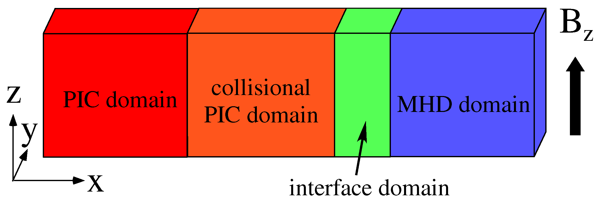
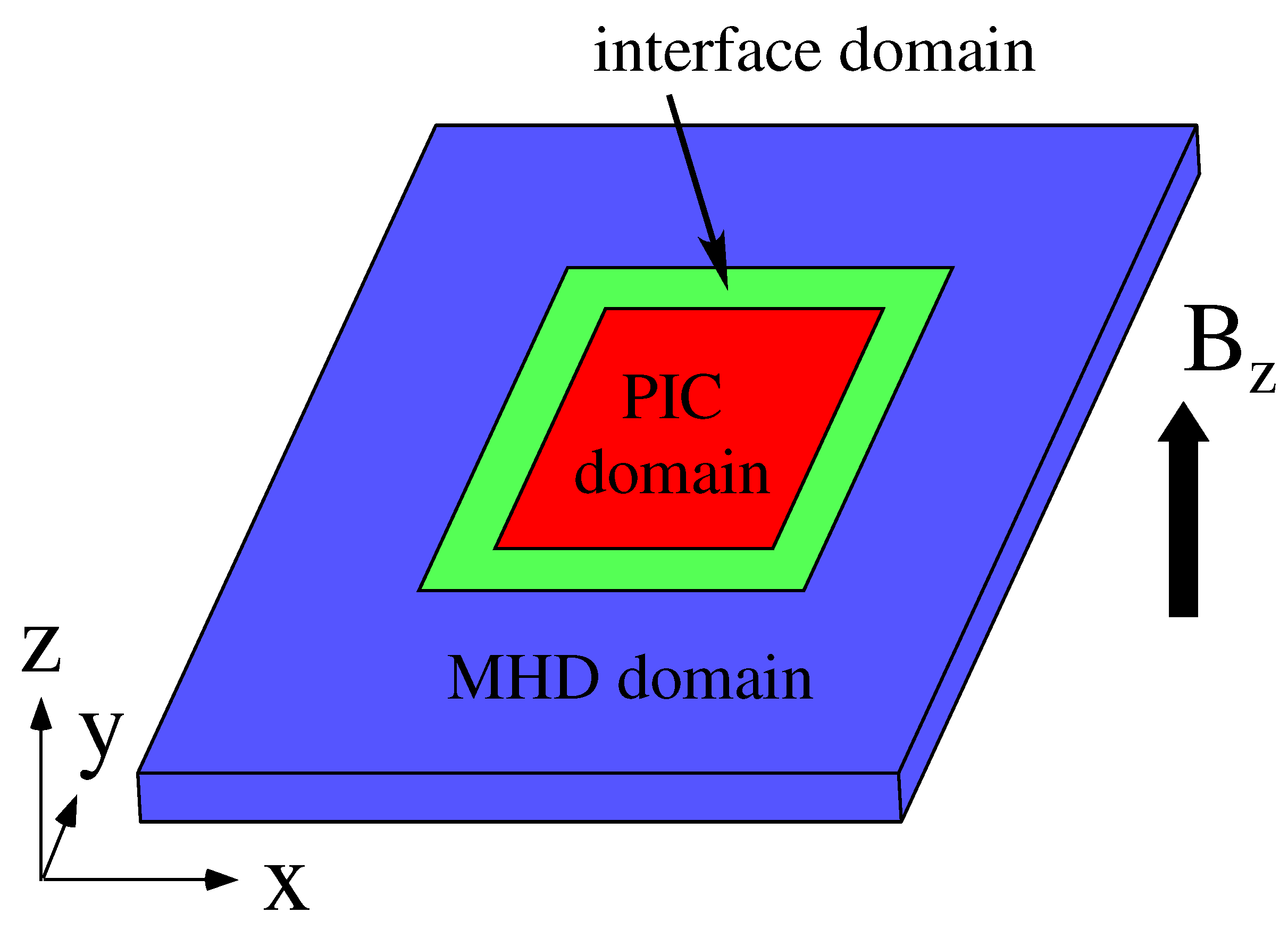
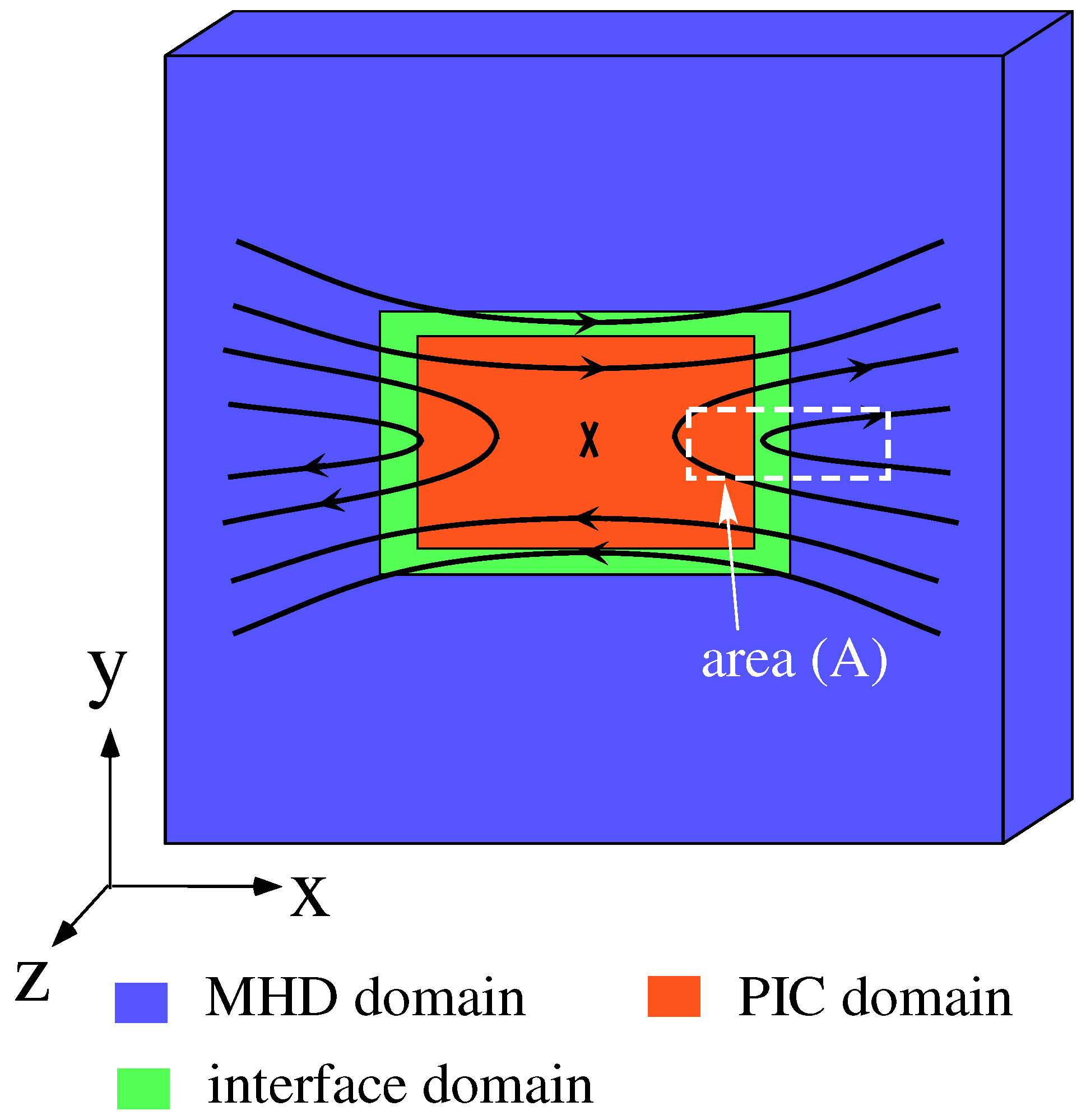
Figure 1 highlights an idealized form of the multi-hierarchy model applied to magnetic reconnection. In this model, the PIC domain is located on the central region and covers the kinetic region including the reconnection point. Surrounding the PIC domain is the MHD domain, and the interface domain is inserted between the PIC and MHD domains. The MHD and PIC domains are interlocked in both upstream (
y-axis) and downstream (
x-axis) directions.
At the present stage in achieving the idealized model shown in
Figure 1, we extend our multi-hierarchy model to three new models named “The Improved Multi-Hierarchy Models 1, 2, and 3”. The Improved Multi-Hierarchy Models 1 and 2 mimic the downstream region of magnetic reconnection and one-dimensionally interlock hierarchies. In The Improved Multi-Hierarchy Model 1, the two hierarchies, the PIC and MHD domains, are coupled, while, in The Improved Multi-Hierarchy Model 2, the three hierarchies, the PIC, collisional PIC, and MHD domains, are coupled. Models 1 and 2 can be regarded to correspond to the area (A) represented by the white dotted lines in
Figure 1. In these models, the propagations of plasmas from the PIC domain to the MHD domain are simulated. The Improved Multi-Hierarchy Model 3 is a model which couples hierarchies two-dimensionally, namely in the two-directional scheme. The upstream condition, however, is used in the two directions. In this model, the propagation of plasmas from the MHD domain to the PIC domain is simulated.
3.1. Plasma Ejection from the PIC Domain to the MHD Domain
In the downstream of magnetic reconnection, the direction of main plasma flow is from the PIC domain to the MHD domain. As the first step of the hierarchy-interlocking in the downstream region, we develop a new multi-hierarchy model based on one-directional interlocking between the PIC and MHD domains.
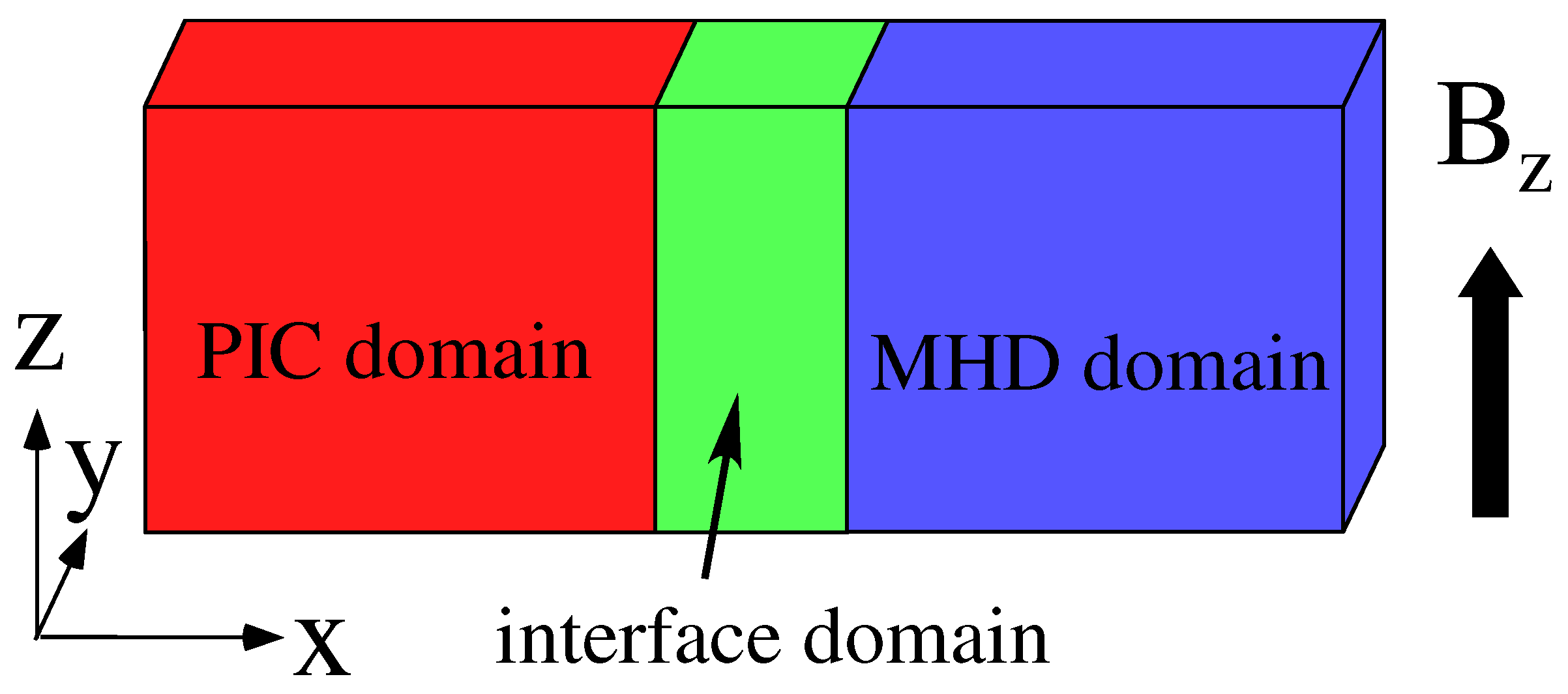
Figure 2 shows a new simulation model named “The Improved Multi-Hierarchy Model 1”. The left region is the PIC domain and the right region is the MHD domain. Between the PIC and MHD domains, the interface domain with a finite width is inserted.
Let us argue an interlocking scheme between MHD and PIC data in the interface domain in the case of the downstream direction. For the hierarchy-interlocking along the downstream direction, which is taken to be
x-axis, we also use the hand-shake scheme with the same form as Equation (
1):
and employ the interconnection function with the same form as Equation (
2):
where
and
denote the boundaries on the MHD and PIC sides in the interface domain, respectively. For the pressure, Equation (
5) is not appropriate, because the use of Equation (
5) causes the unphysical heating or cooling. However, if instead of Equation (
5),
for
and
for
were used as in the upstream direction, the information could not propagate from the PIC domain to the MHD domain. Thus, for the pressure, we adopt a new scheme, in which Equation (
5) is employed as the interconnection function, but the hand-shake scheme for the pressure is modified as follows:
where
is the grid spacing and
N is a positive integer, assuming that the MHD domain is located at the right side of the PIC domain. This means that the pressure at
is the interpolated value between
at
and
at the so-called upwind position
compared with
. This modified scheme results in a successful propagation of the pressure data from the PIC domain to the MHD domain without the unphysical heating or cooling.
In the multi-hierarchy model based on the above scheme, we perform simulations of plasma ejection from the PIC domain to the MHD domain. The simulation domain is implemented on (1376, 4, 16) grid points and the box size is , where is the electron plasma frequency and c is the speed of light. The PIC domain covers the area , the interface domain is located in the area , and the MHD domain occupies the area . The uniform magnetic field is taken to be in the z direction. The system is periodic in the y and z directions and is free in the x direction.
The simulation parameters are as follows. The ion-to-electron mass ratio is
, and the ratio of the electron plasma frequency to the electron gyrofrequency is
. As the initial condition, the plasma density is uniform, and the ion-to-electron temperature ratio is
(the thermal speed of electrons and ions are
and
, respectively.). In addition, initially, the Maxwellian velocity distribution is satisfied in the whole region of the PIC and interface domains. The number of ions (electrons) is initially 1,500,000, and increases to ≃2.1 ×
. The number of particles per species per cell is ≃61 initially, and increases to ≃85. Here, we choose
in Equation (
6).
A plasma is supplied into the simulation domain from the left-side boundary of the PIC domain owing to the drift. The velocity distribution of the supplied plasma also satisfies a shifted Maxwellian distribution with the thermal speed equal to the initial thermal speed. To generate the plasma flow due to drift, an external driving electric field is imposed in the y direction at . The field is set to be zero at the initial time, and gradually grows to reach a constant value . After reaching , is gradually decreased to return to zero, so that the density of the supplied plasma is decreased.
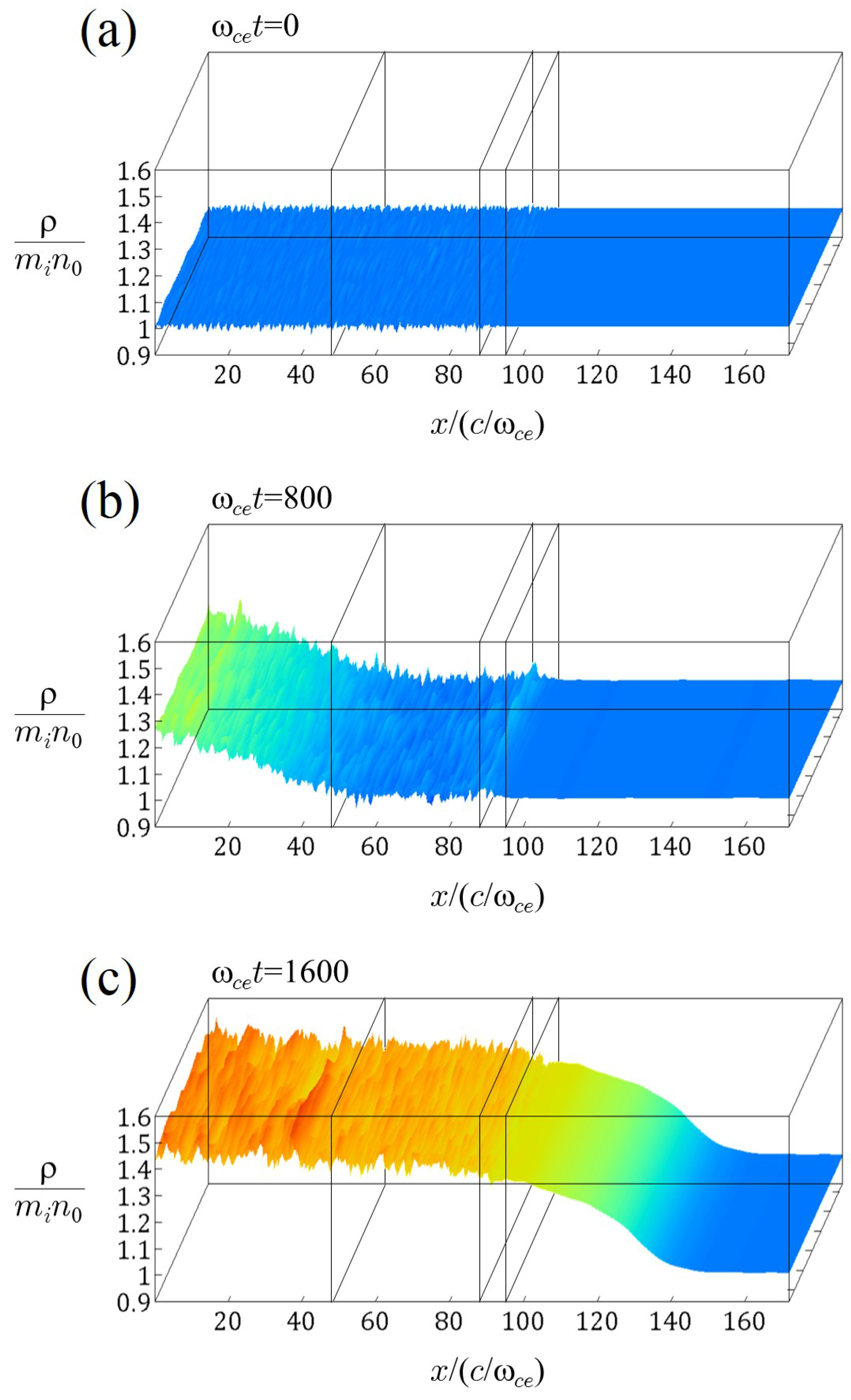
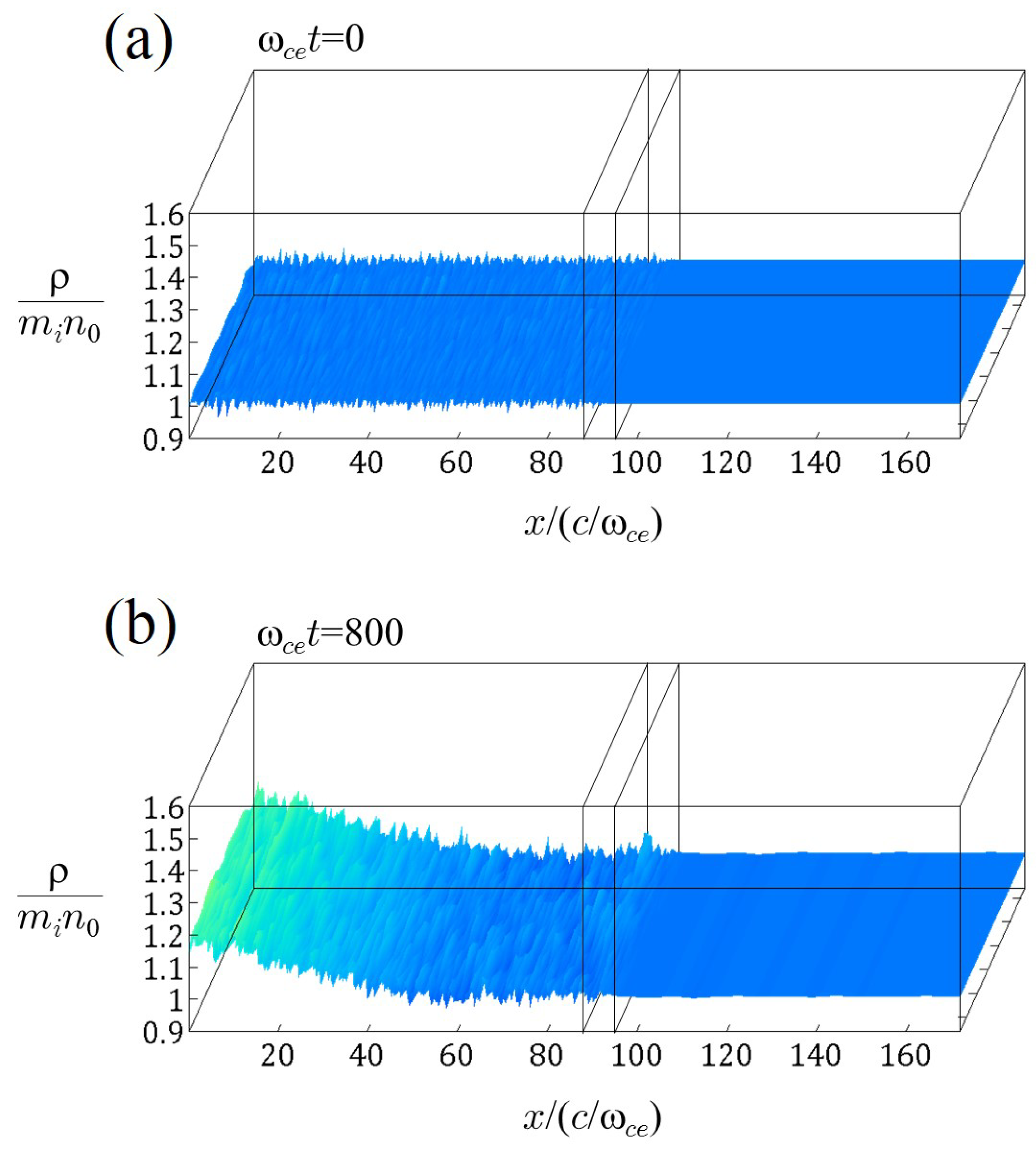
In
Figure 3, we show the spatial profiles of the plasma mass density in
plane at: (a)
; (b) 800; (c) 1600; and (d) 2400. The profiles are enlarged in the
z-axis compared with the actual length. Only the region
is displayed, since the plasma behaviors in
of the MHD domain are trivial. In the panels, the colors also indicate the value of the plasma mass density
as the height. The mass density is normalized to
, where
is the initial number density. At the initial state,
holds in the whole region, where
is the contribution of the electron mass, and small fluctuations are seen only in the PIC and interface domains. At
, the density in the left part of the PIC domain begins to increase, and at
, the plasma is smoothly and continuously propagating to the MHD domain through the interface domain. After that, the density of the plasma supplied from
has been decreased at
. It is confirmed that the information of the decrease in the density can transmit from the PIC domain to the MHD domain.
3.2. Plasma Ejection in the Three-Hierarchy-Interlocking Model
As the second step of the hierarchy-interlocking in the downstream region, we further extend our multi-hierarchy model to create a new model based on three-hierarchy-interlocking. In
Figure 4, we show the schematic diagram of “The Improved Multi-Hierarchy Model 2”, in which the PIC, collisional PIC, and MHD domains are coupled. For the Coulomb collision process in the collisional PIC domain, a Monte Carlo model created by Takizuka and Abe in 1977 [
21] is used. In this collision model, binary collisions of individual particles are calculated. Let us note that the interface domain is located between the collisional PIC and MHD domains, whereas there is no interface domain between the PIC and collisional PIC domains.
By using the above three-hierarchy-interlocking model, we perform simulations of plasma ejection from the PIC domain to the MHD domain via the collisional PIC domain. The simulation domain is implemented on (1376, 4, 16) grid points and the box size is . The PIC domain, the collisional PIC domain, the interface domain, and the MHD domain cover the areas of , , , and , respectively. The uniform magnetic field exists in the z direction. The boundary is periodic in the y and z directions and is free in the x direction.
The simulation parameters are the same as those used in
Section 3.1, with the exception of the number of particles and the collision parameter. Initially, the number of ions (electrons) is 2,000,000 and the number of particles per species per cell is ≃81. The number of ions (electrons) increases to ≃2.9
and the number of particles per species per cell increases to ≃117. We set the collision parameter so that the ion mean free pass is ≃6
. (In the collision model by Takizuka and Abe, the Coulomb logarithm is regarded as an artificial parameter.)
As in the simulations shown in
Section 3.1, a plasma is supplied into the simulation domain from the left-side boundary of the PIC domain by the imposing of
in the
y direction at
. The electron velocity distribution of the supplied plasma satisfies a shifted Maxwellian distribution with the thermal speed equal to the initial thermal speed (
), but the ion velocity distribution does not satisfy a shifted Maxwellian distribution. Regarding the direction parallel to the magnetic field (the
z direction), we take the ion velocities of the supplied plasmas to not satisfy a single Maxwellian distribution, since the Maxwellian velocity distribution is generally violated in the downstream of magnetic reconnection. In this simulation, the ions are taken to be two oppositely-directed streams with the averaged velocities
. The ion parallel velocity distribution is expressed as
The two streams of ions have the same thermal velocity
and the same number density as the other. In the simulation shown below, we take that
and
. In contrast, the perpendicular velocities
and
of the supplied ions satisfy a shifted Maxwellian distribution with the thermal speed equal to the initial ion thermal velocity (
). The
x-axis is the direction of plasma propagation, and thus the
distribution is a shifted Maxwellian with a finite averaged velocity, but the
distribution is a Maxwellian with the zero averaged velocity.
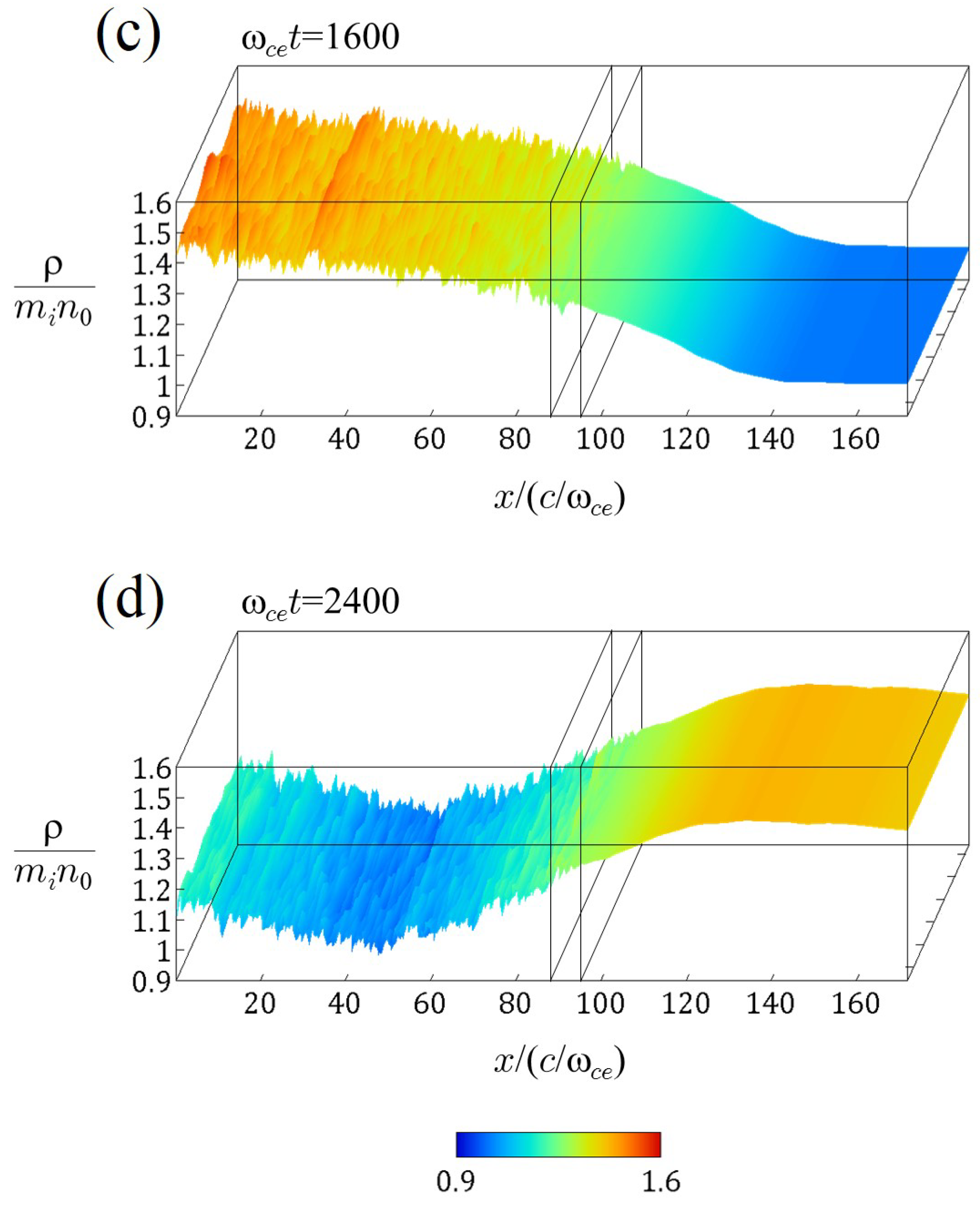
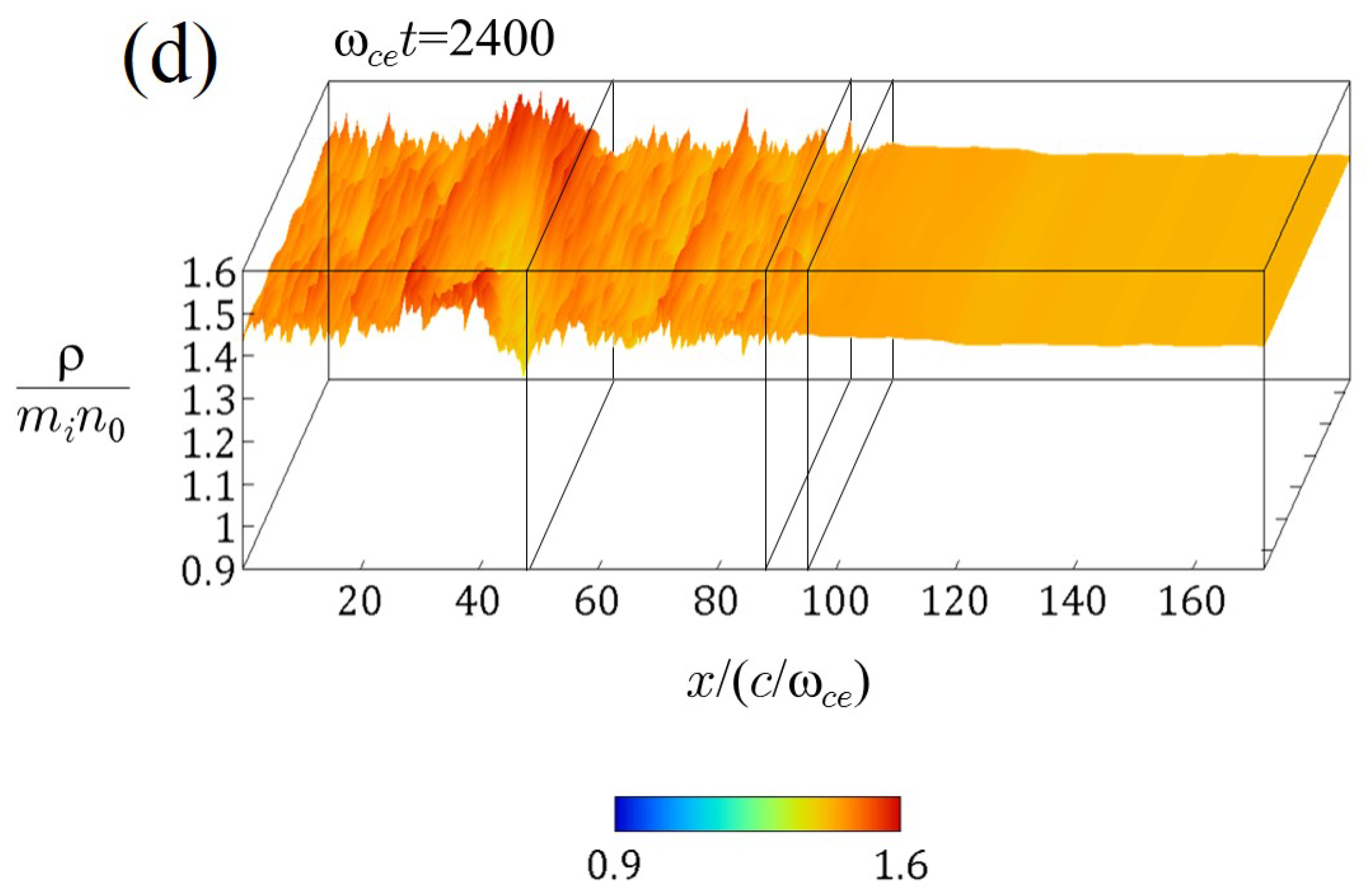
Figure 5 shows the spatial profiles of the plasma mass density in the
plane at: (a)
; (b) 800; (c) 1600; and (d) 2400. As in
Figure 3, the profiles are enlarged in the
z-axis, only the region
is displayed, and the colors and the height indicate the value of
. Initially, the plasma density is uniform, and small fluctuations exist only in the PIC, collisional PIC, and interface domains. At
, the plasma supplied from the left-side boundary begins to enter the collisional PIC domain. Furthermore, the plasma smoothly and continuously propagates to the MHD domain via the interface domain at
. We can see that a density variation in the
z direction is excited in the PIC domain. This density variation likely originates from the two streams of ions supplied from the left-side boundary. At
, the density variation is intensified. However, the density variation disappears in the collisional PIC domain and thus does not transmit to the MHD domain.
Let us confirm that the Coulomb collision plays the main role in the relaxation of the two streams and the damping of the density variation observed in The Improved Multi-Hierarchy Model 2.
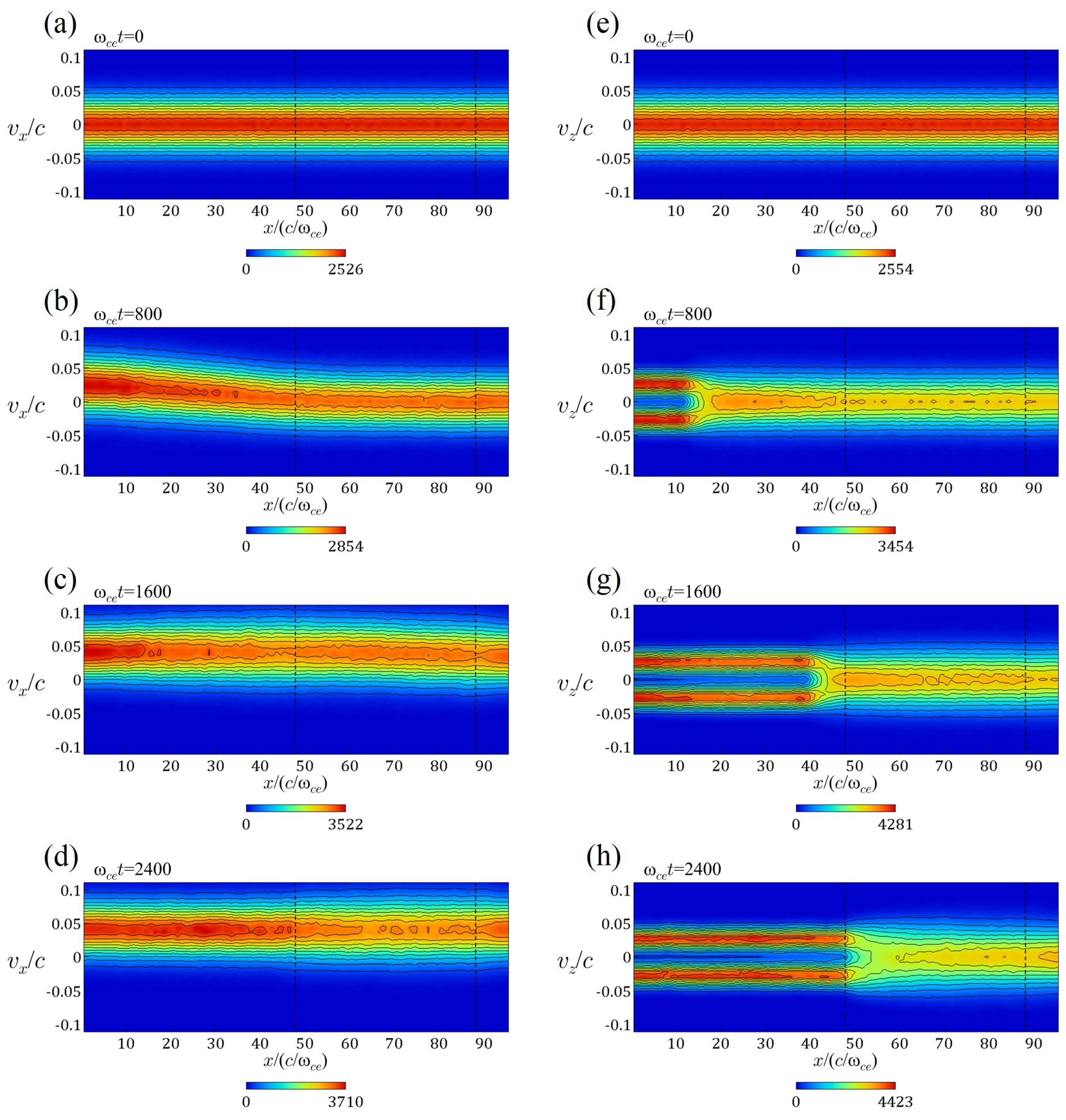
Figure 6 shows ion distributions in the phase space of the simulation shown in
Figure 5 at various times. Note that only the PIC, collisional PIC, and interface domains are shown. The vertical dotted lines denote the boundary between the PIC and collisional PIC domains (
) and the boundary between the collisional PIC and interface domains (
).
Figure 6a–d indicates the distributions in the phase space
, where
is the velocity parallel to the plasma propagation. Through the simulation, the
distributions satisfy the shifted Maxwellian distribution. At the initial time, the averaged velocity is zero in the whole region. We can see that the averaged velocity shifts to positive in the left part of the PIC domain at
. At
and 2400, the plasma has the same averaged velocity (≃0.04
c) in the whole region. In contrast,
Figure 6e–h represents the distributions in the phase space
, where
is the velocity perpendicular to the plasma propagation. Initially, the Maxwellian distribution holds in the whole region. We can find that the two-stream plasma begins to be supplied from the left-side boundary of the PIC domain at
. At
, the two-peak distribution propagates in the right direction and approaches to the collisional PIC domain. At
, the two-peak distribution has entered the collisional PIC domain. We can observe that the two-peak structure of the
distribution is relaxed to a one-peak distribution as the plasma propagates in the right direction in the collisional PIC domain. This relaxation is clearly due to the Coulomb collision effect installed in the collisional PIC domain. As a result, a shifted Maxwellian distribution is fully satisfied in
, and thus the plasma can smoothly eject to the MHD domain.
3.3. 2D Hierarchy-Interlocking Model
We develop a multi-hierarchy model based on a two-dimensional (two-directional) hierarchy-interlocking [
7,
22] as shown in
Figure 7. This model is named “The Improved Multi-Hierarchy Model 3”. The PIC domain is located in the central area, the interface domain surrounds the PIC domain, and the MHD domain is the outermost area and, further, surrounds the interface domain. Thus, the domain is expressed as follows. The PIC domain:
; the interface domain:
; and the MHD domain:
.
Unlike in
Section 3.1 and
Section 3.2, we use the hand-shake scheme for the upstream direction:
The interconnection function
F, however, must be changed to a two-dimensional function. We employ
F expressed as
where
Only for the pressure (the thermal velocity), we use
Note that
F is used only in the interface domain.
By means of The Improved Multi-Hierarchy Model 3, we perform a plasma flow injection from the MHD domain to the PIC domain to confirm its physical reliability. The simulation box size is , and the number of grid points is . The PIC domain covers the region , the MHD domain is the area , and the interface domain is the narrow region with the width between the PIC and MHD domains.
In this simulation, we adopt non-uniform grids in the
x-axis and
y-axis [
17]. The grid spacing
and
is a function of the coordinates
x and
y, respectively. The grid spacing
in the PIC and the interface domain is
. In the region of
,
is the smallest (
), but in the region of
, the grid spacing is larger and reaches
at
. The same manner is applied to
as a function of
y. We set that
. The uniform magnetic field
is taken to be in the
z direction. The system is periodic in the
z direction and is free in the
x and
y directions.
As simulation parameters, we set , , , and (). In addition, as the initial condition, the Maxwellian velocity distribution is satisfied in the whole region of the PIC and interface domains, and the plasma density is uniform. The number of ions (electrons) is initially 6,400,000, and increases to ≃1.3 . The number of particles per species per cell is ≃49 initially, and increases to ≃99.
Plasmas are supplied from the outside boundary of the MHD domain. For generating plasma inflows, an external electric field is imposed in the y direction on the line of and is imposed in the x direction on the line of (. The fields and , which are set to be zero, grow first at the center positions on the line and on the line , and the width of the regions where the field is imposed expands to y and x directions, respectively. Eventually, and develop to reach to the constant values on the entire lines of and .
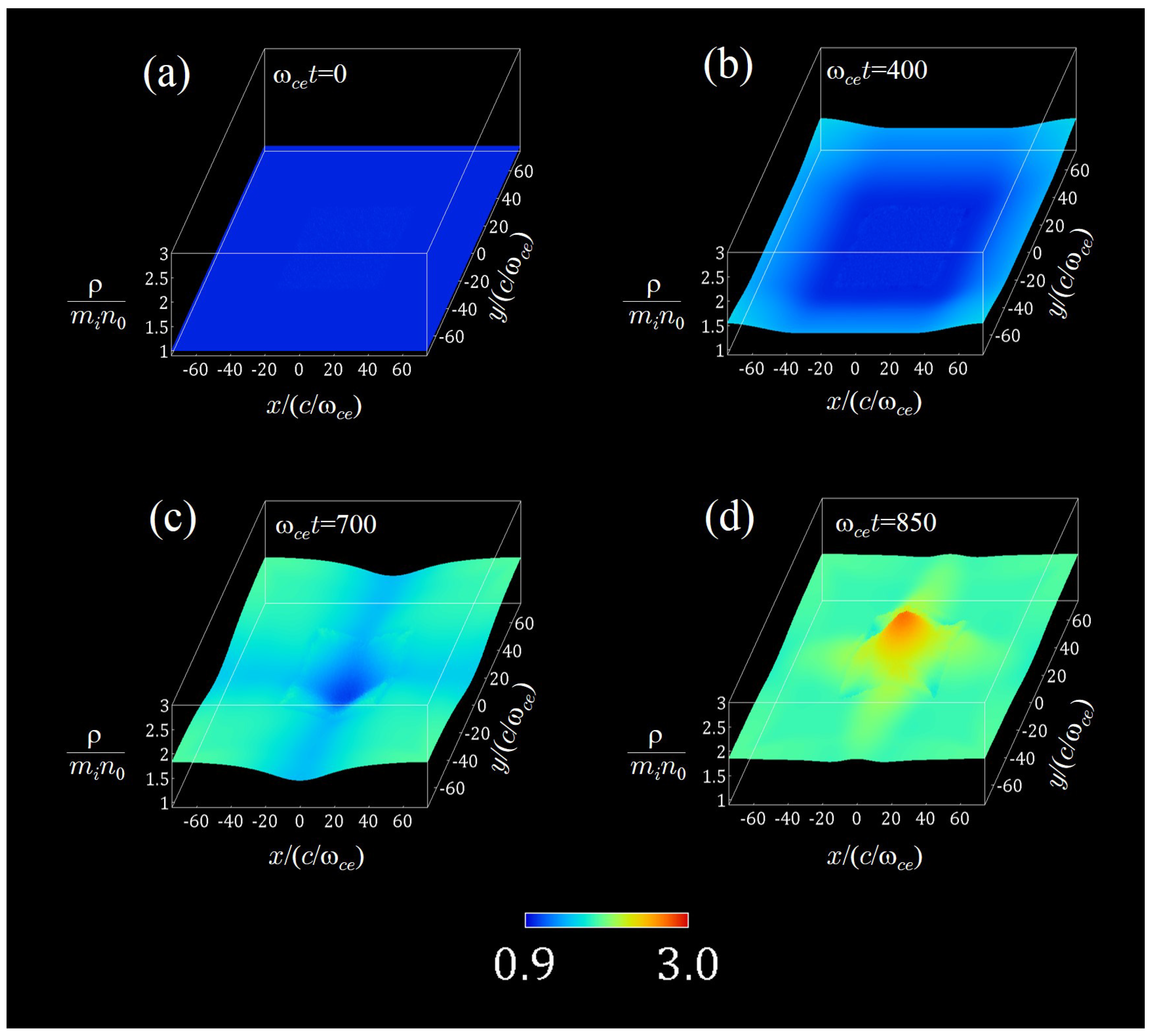
In
Figure 8, we demonstrate the spatial profiles of the plasma mass density in
plane at: (a)
; (b) 400; (c) 700; and (d) 850, where the mass densities at
, 700, and 850 are averaged over 11 snapshots of the mass densities, respectively. As in
Figure 3 and
Figure 5, the plasma density is normalized to
, and both the colors and the height indicate the values of the density. The initial density is uniform (
) in the whole region. The density in the surrounding MHD domain begins to increase at
, and the plasmas are smoothly injected to the central PIC domain through the interface domain at
, although small noise is seen in the interface domain. At
, the plasma flows have collided at the center of the PIC domain, and then the plasmas are accumulated in the PIC domain. It is confirmed that plasmas are injected smoothly from the MHD domain to the PIC domain by using the two-dimensionally interlocking method.


