1. Introduction
The electrical power grid is a significant part of our daily life activities, as well as industry development. Therefore, upgrading the electric power grid is essential, which involves enhancing the power system reliability and efficiency. Upgrading the electric power network includes upgrading the power generation, transmission, distribution and measuring instruments. One of the essential aspects of these upgrades is improving the communication abilities in terms of monitoring and metering equipment to achieve the reliable information communication technology of the electrical grid [
1]. Therefore, the Ethernet is applicable for real-time environments with the ability to create a full duplex-exchangeable connection and reordering of the network congestion with IEEE standard 802.1Q, based on it is priorities in the network. The backbone feature of IEEE standard 802.1Q is to support the Virtual Local Area Network (VLAN) isolation of traffic, which is significantly important to managing the information throughout the network. Consequently, a significant number of industries have started utilizing Ethernet in their networks.
In turn, the forward packets method is utilized in the network to establish a transition communication between networks and introduce the concepts of next-generation technologies, for instance, colorless, directionless and contention fewer networks [
2]. The concept of the next generation network (smart gird) has the conventional power technology that integrated with non- conventional information and communication technology and makes it possible to offer energy and information services concurrently. The intelligent power grid, that has several sensors connected through an intelligent communication network and data acquisition system, is known as a smart grid. This system uses real-time analysis by utilizing the computing system that will enable predictive, rather than reactive, responses to sudden disruptions; therefore, integrated two-way communications and a networking platform are essential to the intelligent network [
3,
4,
5].
The universal communication standards that are implemented in smart grid devices are known as the International Electrotechnical Commission (IEC), such as the IEC 61850 standard. IEC 61850 is a creative approach that requires new plans for the most proficient methods to computerize the substations. The object-oriented approach requires the high capacity of data for transmission with critical cost investment funds because of unwavering quality (repeatability) and adaptability of uses. Furthermore, the IEC 61850 family is a standard used in intelligent networks that represents the key component for the Substation Automation System (SAS), as well as protecting the transmissions within the network. The main function of the IEC 61850 is establishing a standard communication that matches the existing requirements of the main upstream power grid [
6,
7].
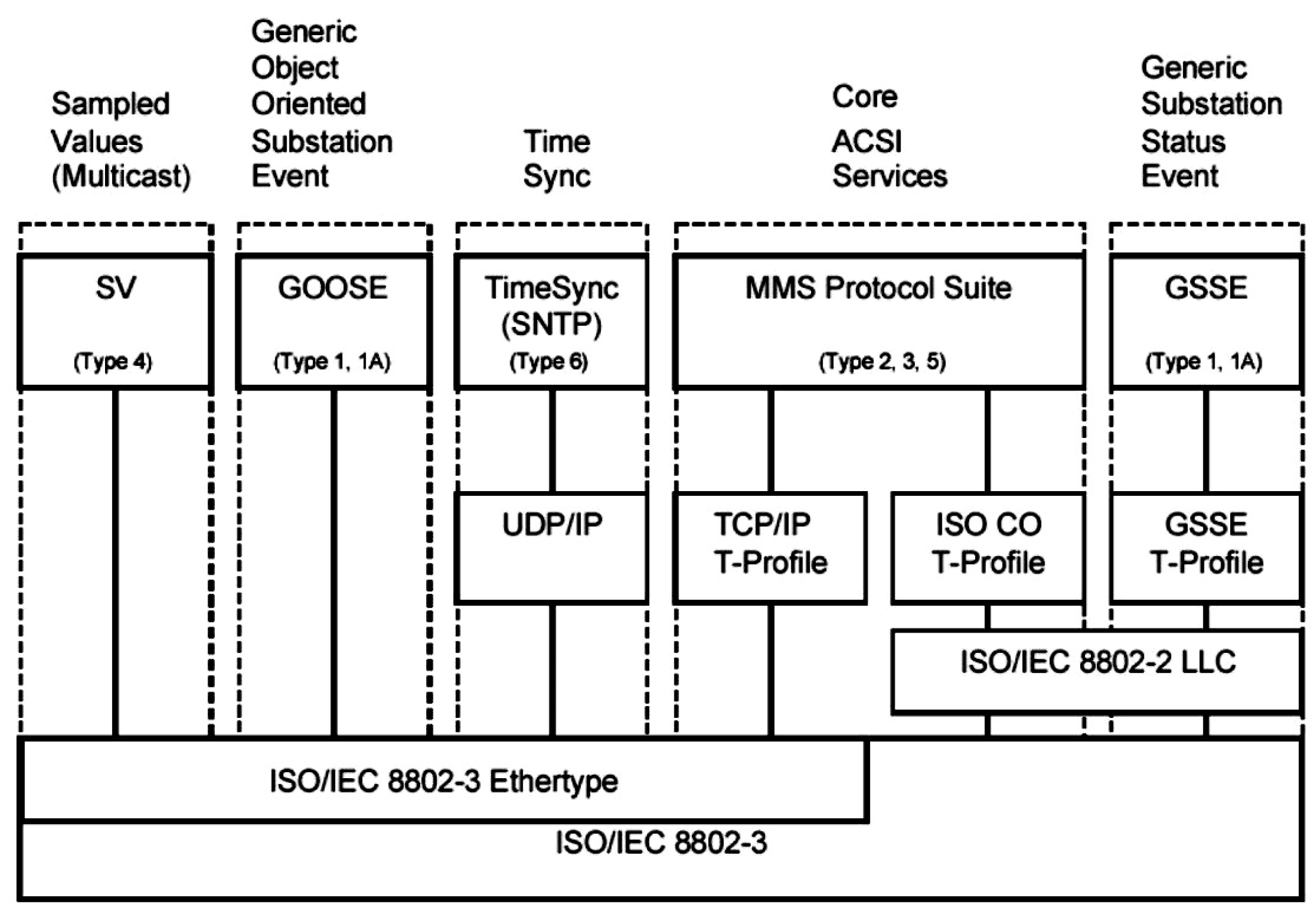
However, because of the availability of the new high bandwidth medium in advanced communication technologies, IEC 61850 has been developed to be an inter-substations standard. IEC 61850 characterizes the data models and the conceptual administrations (abstract services) to get to the information. The abstract services are characterized in IEC 61850 in a unique way that can be mapped into various conventions. Many existing characterizations in the IEC 61850 standard are to MMS (Manufacturing Message Specification) and GOOSE (Generic Object Oriented Substation Event) which are used for time-critical events, for instance, the insurance of the electrical hardware equipment shown in
Figure 1 [
8]. In addition, due to the availability of the new high bandwidth communication medium in advanced technologies, IEC 61850 needs an Ethernet physical system that ordinarily utilizes high-speed switches to support the system connectivity with Ethernet as the physical layer. This has resulted in the IEC 61850 being extended to become an inter-substations standard that has the ability to forward all messages to any appliance in the network within 2 to 4 ms [
9]. Recently, the extra object models have become widely accepted as it achieves the benefits for industries by vendors. Oil and gas industries, as well as water manufacturing, are good examples of being object-oriented.
Based on that, IEC 61850 cannot be just a communication standard; rather, it is an inclusive standard utilized for designing the automation systems. It adds arrangement and structure to information which is generally unformatted. Furthermore, it is a combination of several standards and concepts that, working together, facilitate the design, utilization and operation of devices. Features of IEC 61850, such as the high-speed peer-to-peer communications, are used to replace the conventional method of the hard-wired control signals that exchange among IEDs for protection and control purposes [
11].
In this paper, our research is motivated by the means of providing a simple switch architecture that has the ability to achieve flow packets management in the network with low packets losses. Accordingly, the essential objective of IEC 61850 in this work is to present the control intelligence network communication for managing the transfer information through the network in the substation automation environments, and to operate it on protocols of top standard communication. Furthermore, utilizing the GOOSE protocol with time-critical operations, such as tripping, is one of the main challenges in this study, because of the possibility of failure due to the massive traffic congestion with constant generation packets of multiple events. Thus, it is crucial to provide reliable design rules for the substation automation switch, that has proper modeling and consistent configuration parameters. The rest of the paper is organized as follows: GOOSE protocol background is presented in
Section 2.
Section 3 goes on to detail traffic management in the communication network. The switch design architecture presented in detail in
Section 4. Simulink design of the proposed substation switch is explained in
Section 5. Results and discussion of the numerical results are discussed in
Section 6.
Section 7 presents the conclusion.
2. GOOSE Protocol
Timing in the operation of the electrical SAS is significantly important, as well as the need for high reliability and accessibility of the Substation Communication Network (SCN) [
12]. These constraints can be met by utilizing the IEC 61850 standard, due to it is ability to deliver fast response information via the Generic Substation Events (GSE) for peer-to-peer communication mode by using the GOOSE protocol. GOOSE protocol is an abbreviation of Generic Object Oriented Substation Event. It works to maintain the exchange of a broad range of common information that is structured by a DATA-SET, for example, the synchronization of the circuit breakers, distance protection and overcurrent breakers [
13]. In addition, the GOOSE is planned to support the means of the high priority as well as support the high-speed peer-to-peer communication of the IEDs (Intelligent Electronic Devices) of the Ethernet LAN to protect the network. In other words, GOOSE protocol is designed to replace the conventional way of the hard-wired technique [
13].
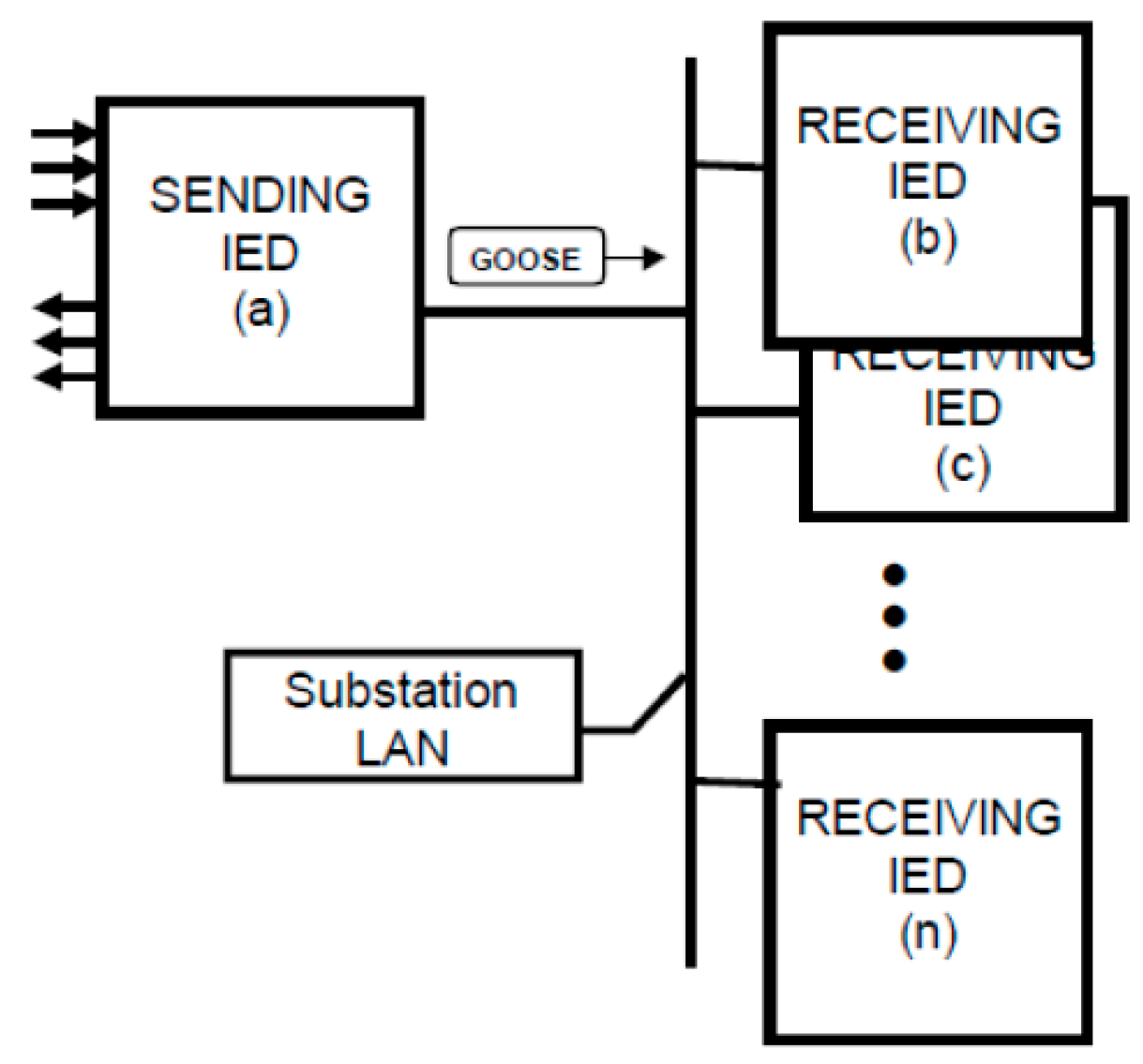
One of the unique functional requirements identified for the IEC 61850 standard is the high-speed communication from one device to several devices of simple binary state data. Forwarding many messages to several devices simultaneously can cause undesirable delay; this kind of function is called multicast, as shown in
Figure 2. The multicast utilization is applied by the MMS information (Manufacturing Message Specification) report service. The data report uses a binary object model (device combination of the binary states) known as GOOSE [
14]. The Multicast function address is usually forwarded to all devices on a Local Area Network (LAN). Normally, the messages forward to a few specific devices in the network and do not need to be forwarded to all devices. Therefore, to reduce this problem (Ethernet traffic), the conception of a “Virtual” LAN or VLAN is employed [
8].
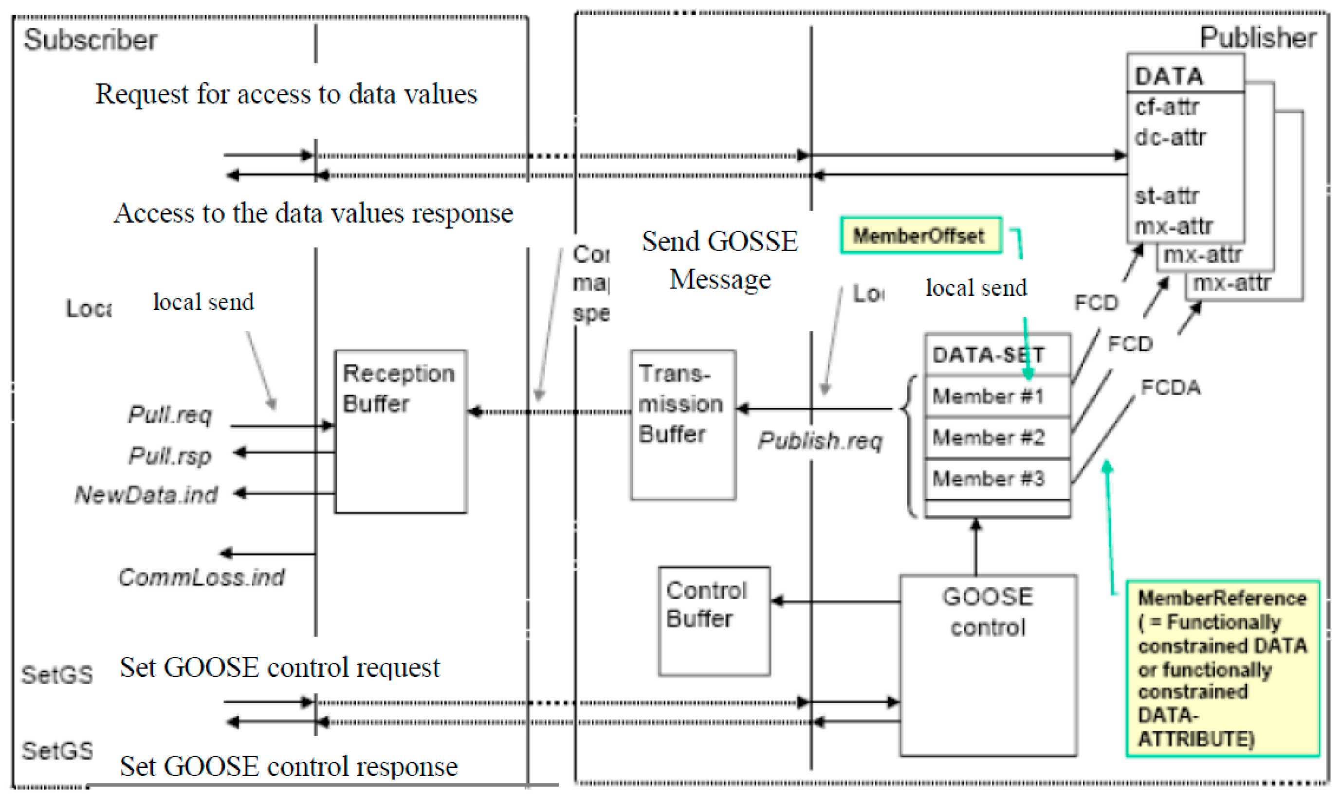
IEC 61850 GOOSE message transmits a set of information that is “Published”, based on any changes in IED information. Any device connected to the LAN and involved in the published information has the ability to “Subscribe” to the Publisher’s GOOSE message and utilize the information that is provided by logical node or logical device in the message when it is required, as illustrated in
Figure 3. Accordingly, the GOOSE protocol is known as a Publish–Subscribe message. The GOOSE message is launched in three scenarios. The first scenario is when an IED is switched on and becomes ready to operate, then a GOOSE message is sent to inform all devices of the IED statement. The second scenario occurs when there is a change in the status of any IED device in the network, then the GOOSE message is sent to inform other devices [
14,
15]. The third scenario occurs when the user-selectable periodic basis occurs [
16]. This latter scenario is when there is no update of the publisher statement devices, the subscriber devices cannot identify if they are still alive (or, connected) in the network. Therefore, if the subscriber devices fail to receive the regular GOOSE message from the publisher, then the publisher would be assumed “dead” and set default statements on the binary variables that are expected from a dead device. Consequently, the third scenario is useful for the communication situations that have a huge information flow and need high real-time speed.
Indeed, GOOSE has been planned to be utilized in a high speed and reliable way over the SAS. Meanwhile, the IEC 61850 devices have been tested by many vendors, such as KEMA. The results of that test indicated the reliability of the GOOSE messages in the tripping of breakers. The GOOSE message takes 4 ms, from occurring fault position to the trip operation, to take the necessary action to correct the fault and protect the substation from shutdown; this characteristic has made GOOSE protocol the superior protocol for the IEC 61850 Standards [
18,
19].
3. Network Traffic Management
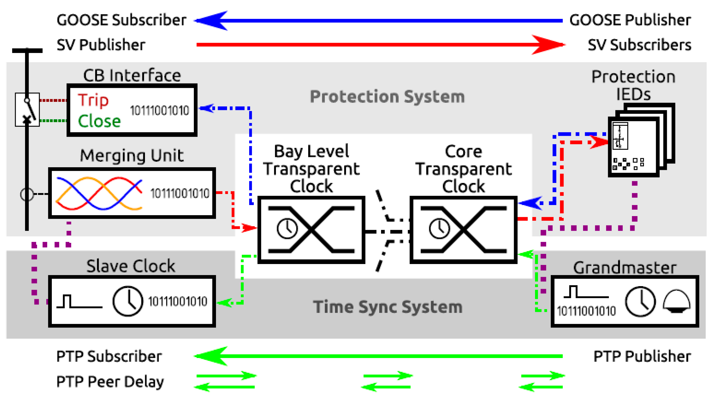
The network communications have many functions that help to share the Ethernet network which help to exchange messages such as Sampled Values (SV), GOOSE and so on, between devices and the control room. Several standards, such as IEEE standard 1588, have recommended the Precision Time Protocol (PTP) for SV messages synchronization [
20]. The traffic volume of PTP is low, generally around 300 bytes per second, which in turn cannot influence the operation of the SV or GOOSE.
Figure 4 depicts the sharing network communication between the switchyard devices and the control room. The traffic of the Ethernet flows in a bi-directional manner, with a possibility of interaction in the bay and the core Ethernet of the switches. The Ethernet switches will be straightforward tickers if PTP is utilized for synchronization, because of the prerequisite of the PTP power profile to utilize the peer delay technique.
Traffic management is essential in the communication network environment especially with the multicast technique that is associated with SV, GOOSE and PTP. Multicast and VLAN filtering methods are utilized for stopping overloads on the edges of the device (such as protection relays), and for limiting the transmission data of the multicast function to specified devices only that are addressed in the data message [
21,
22].
4. Switch Architecture Design
The main objective of the switch is receiving the arrived packets from the input ports and forwarding them to the output ports. Normally, when a single packet arrives at specific periods of time, there will be no collisions between packets in the switch and forwarding the packets directly to the output ports with minimum latency. Unfortunately, in the SAS, this scenario is not applicable because of the sudden changes. Therefore, when the number of events increases, the possibility of collision increases as well. Furthermore, when multiple packets are orientated to the same output ports and arrive from different input ports of a switch at almost the same time, both packets cannot send instantly, and only the single packet can be forwarded through the output ports. Therefore, one of the packets must be kept in the buffer to be forwarded later. The highest rate that the switch can operate on depends mainly on the effectiveness of the switch, namely if it is capable of resolving the collisions between packets within a short time. In this work, the parameters of the switch architecture design are set as follows [
23]: the processor service time is set to 20 ms, buffer capacity is set to 164 packets per second and the inter-arrival time between packets is 4 ms.
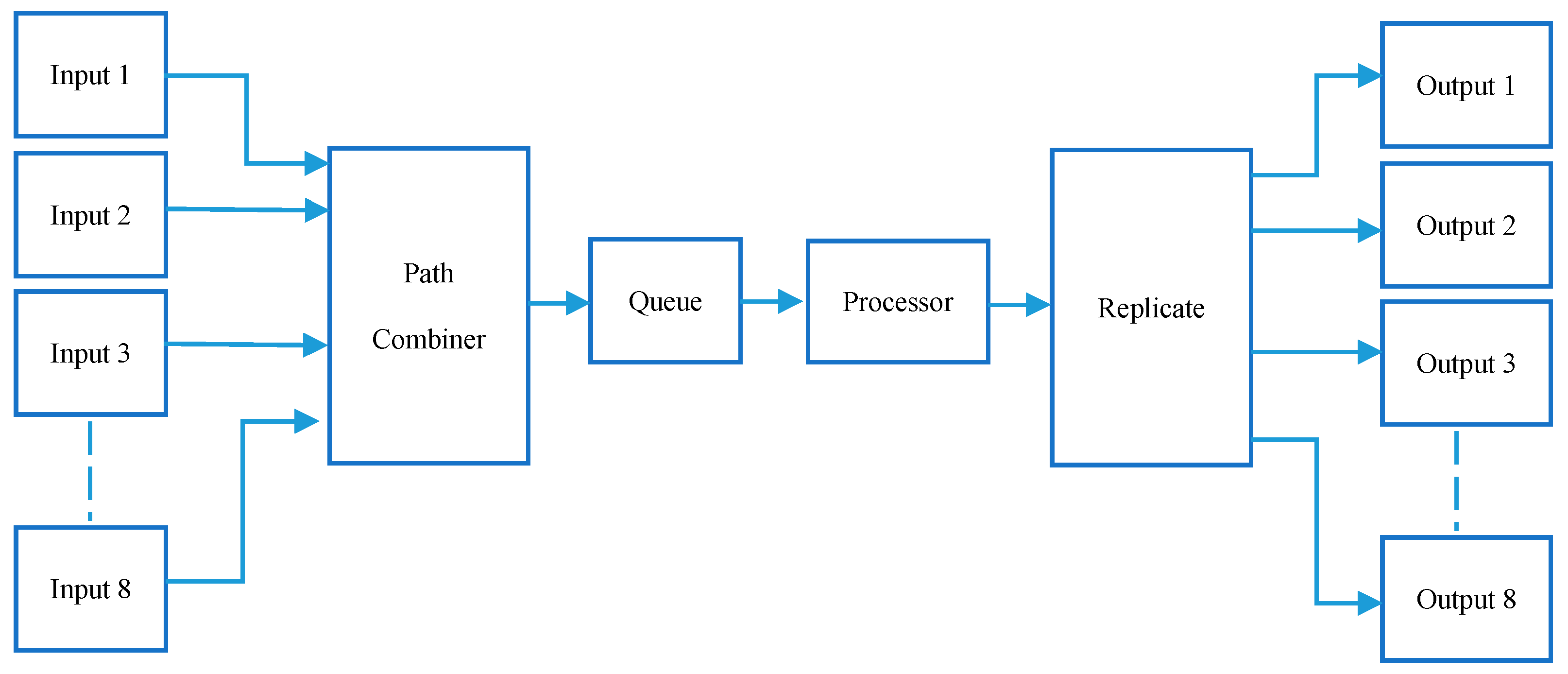
In addition, the block diagram of GOOSE protocol transmitter and receiver is designed by using Matlab/Simevents software. The functionality of the GOOSE transmitter relies on several factors, such as the modeling accuracy of the generation events, reliability and security of forwarding events from the generation side to the receiver part. In the GOOSE protocol, a group of signals generated from the Signal Generator block represents the input data. The input data will be combined together in a single path through the Path Combiner. Consequently, there will be a single path from the path combiner to the next block. A processor (CPU) processes the events coming from the path combiner and forwards them to the output ports. A question that arises at this stage is, if the CPU is busy and more events are coming in, what will happen to those events (packets)? The answer is that these events would simply drop before being processed.
However, if the number of the drop packets increases, then the system reliability is compromised. Therefore, we seek a solution to solve such a problem. In line with this, a buffer block with defined size is utilized and located between the path combiner and the CPU. In other words, it is a storage block for GOOSE packets to store them while the CPU is busy. The waiting time of the events (packets) inside the buffer depends on the processor speed. All the buffers in the switches have potential sizes that are dependent on the manufacturing and case study requirements. In this research, the proposed size of the buffer is 2 Mbits (164 packets) drawn from the industrial switch (RUGGEDCOM) [
23]. The proposed switch architecture of the substation automation is fully managed by the Ethernet switch with eight I/P and O/P ports. The switch is designed to work in a highly reliable manner in harsh industrial environments, as well as with a high level of immunity to electromagnetic interferences.
Figure 5 demonstrates the proposed switch diagram. In addition, two scenarios have been conducted in this work to address the robustness of our proposed switch. In the first scenario, a normal switch with one buffer and with two buffers has been used to store the packets while the CPU is busy with processing other events. In the second scenario, however, four switches are connected internally through a developed control technique to process the packets (events) and prevent packet collision between switches. Finally, the two scenarios are compared with other industrial switch to verify our proposal.
5. Implementation of Switch Architecture in Matlab/SimEvents
Matlab/SimEvents is one of the most significant software in the engineering area. Developing a switch architecture that can cope with the GOOSE protocol requirements in SimEvents tool is not an easy task and not many studies have been done in this particular area. Therefore, choosing the proper blocks to construct the proposed switch was an essential task in this work. The switch design consists of three important parts: transmitter, queuing and processing, and receiver. The transmitter part is a set of events generated by “Time-Based Entity Generator” block in SimEvents. These events were generated in a specific time depending on the case study requirements; in this paper, the generation time of the events set to 4 ms based on the RUGGEDCOM switch [
23]. The events were forwarded from the transmitter to the processor for processing. The processor (CPU) is represented by the “Single Server” block in SimEvents. When the Single Server block is busy processing the incoming events and the transmitter keeps sending more events, the extra incoming events are stored in the FIFO (First Input First Output) buffer for a finite period of time until it gets permission from the CPU to release them and send the packets to the processor and then to the receiver. The receiver part of the switch is modeled using the “Entity Sink” block in SimEvents.
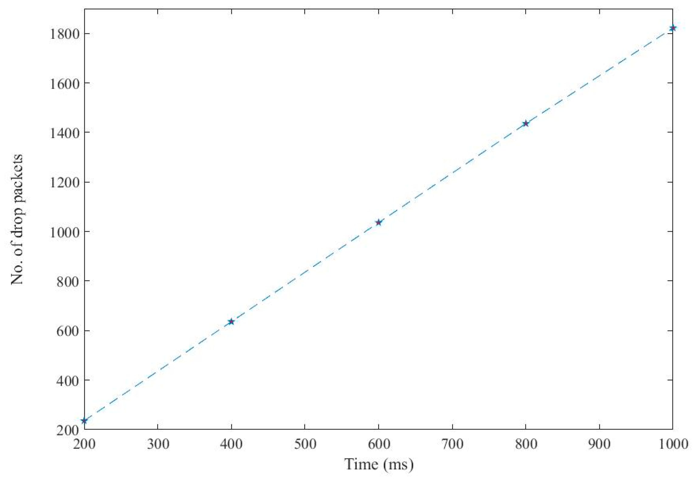
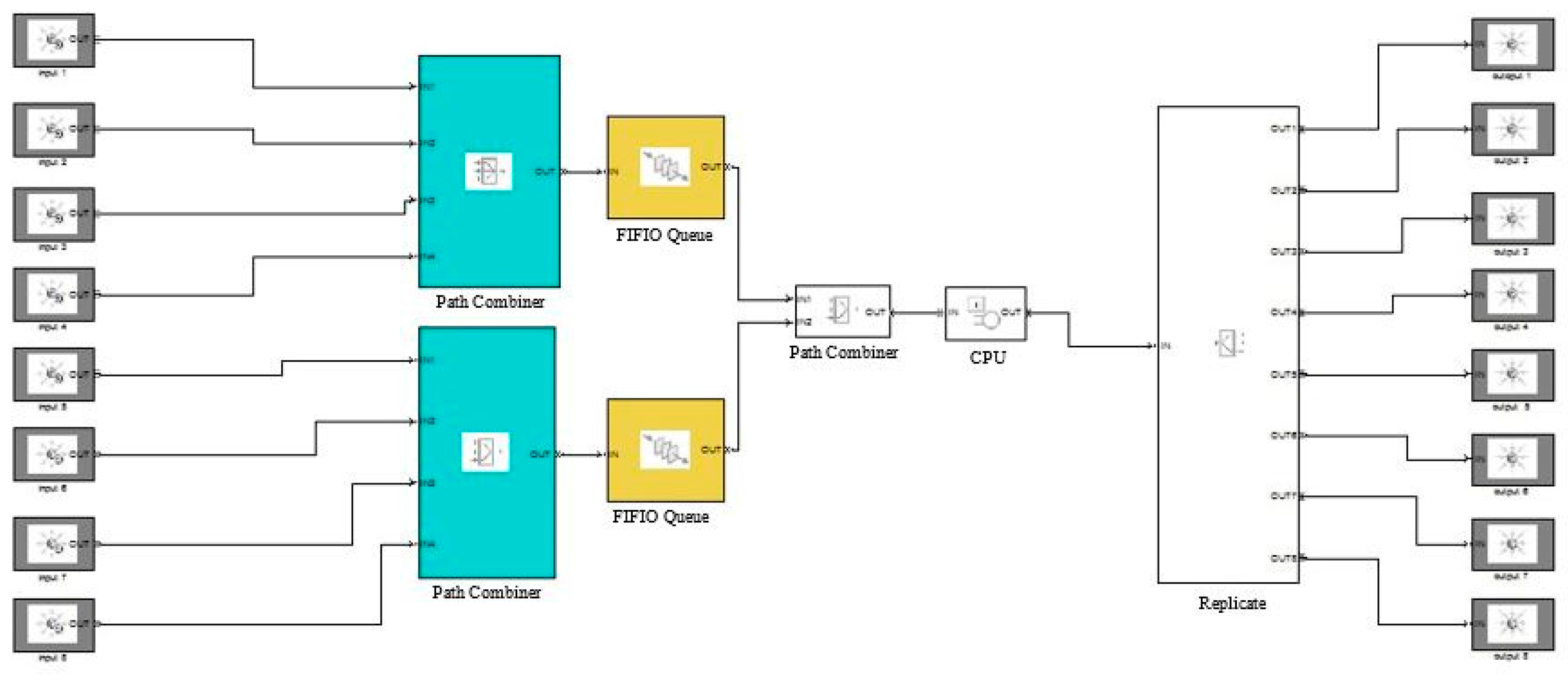
Figure 6 shows the proposed switch by using SimEvents software. The scenario of the drop packets happens when the number of events that come from the input generators exceeds the overall capacity of the processor. Such an occasion reduces the reliability of the system; therefore, calculating the number of drop packets is crucial in this study and it is formulated as follows:
5.1. Scenario Ι: Two Buffers
Installing multiple identical buffers in the proposed switch was carried out as the switch performance improved with increasing the storage space. In turn, that meant providing extra space to keep the packets while the others were processed by the CPU. This scheme reduces the chances of the drop packets, which influences the switch reliability. To ensure both buffers are working with the same reliability, we divided the input ports into two groups and each group had four input ports. Consequently, the first four inputs connected to the upper path combiner and then to the first buffer, while the second group of the input ports connected to the lower path combiner and then to the second buffer. Finally, both buffer outputs connected to the path combiner that converts it into one path connected to the CPU.
Figure 7 demonstrates the switch design of the two buffers in SimEvents.
5.2. Scenario ΙΙ: Four Switches Mechanism
Installing two buffers in the same switch can help to minimize the drop packets in the networks but will not minimize the processing time of the events. Furthermore, adding an extra buffer will cause other issues, such as costing extra money; or major device failure, which would mean any power interruption to the switch would shut down the network; or performance issues (CPU), increasing the number of buffers will not make a difference on the CPU processing speed especially if the time of generating events is faster than the time of processing the incoming events; or hardware complexity, which would mean adding a new hardware in the switch that will increase the complexity of the switch.
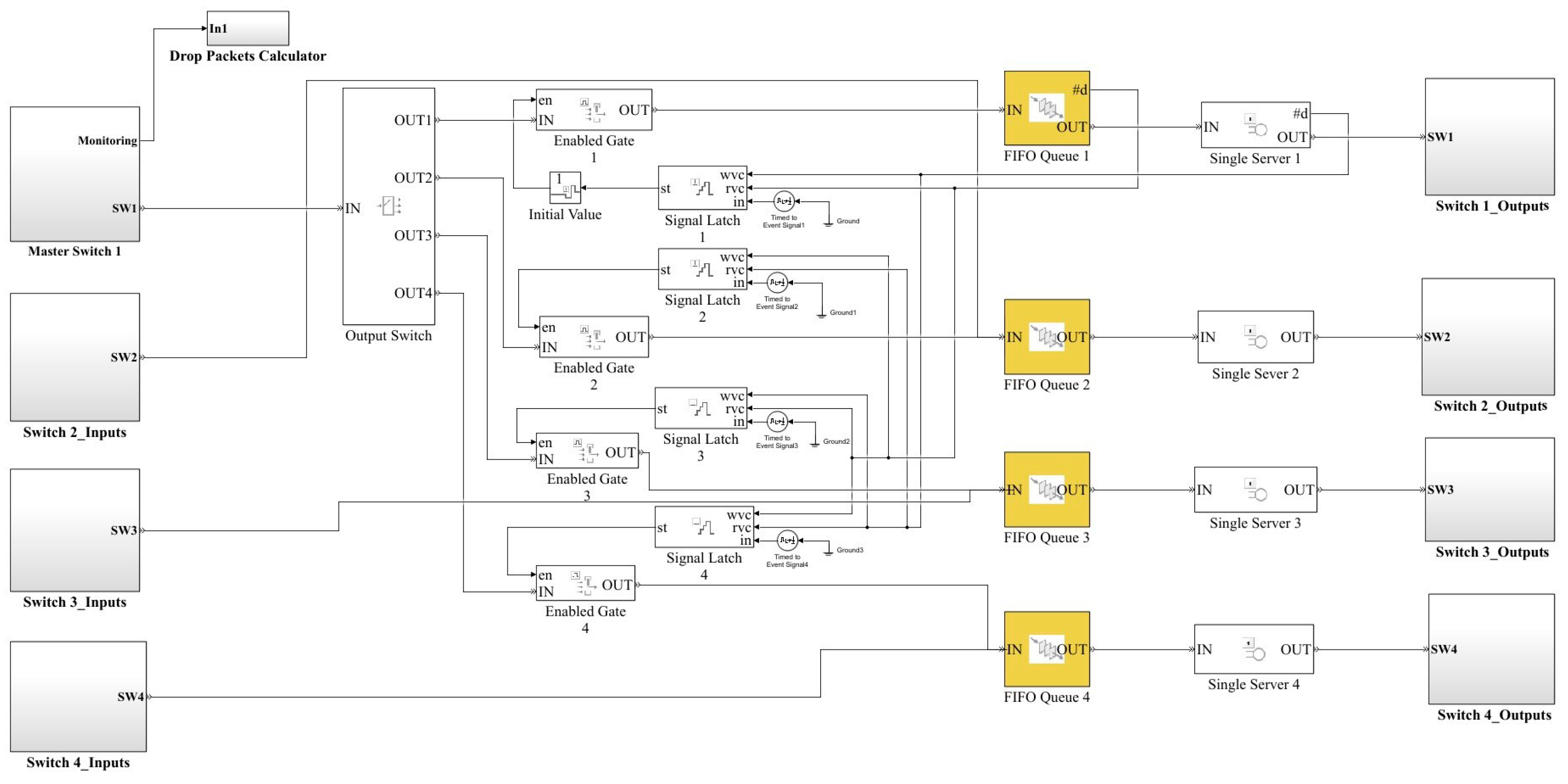
Seeking a solution for these problems has been carried out in this section. The four switches technique is proposed as an improved technique for scenario one, that has one master switch and three salves switches working as a single system, as shown in
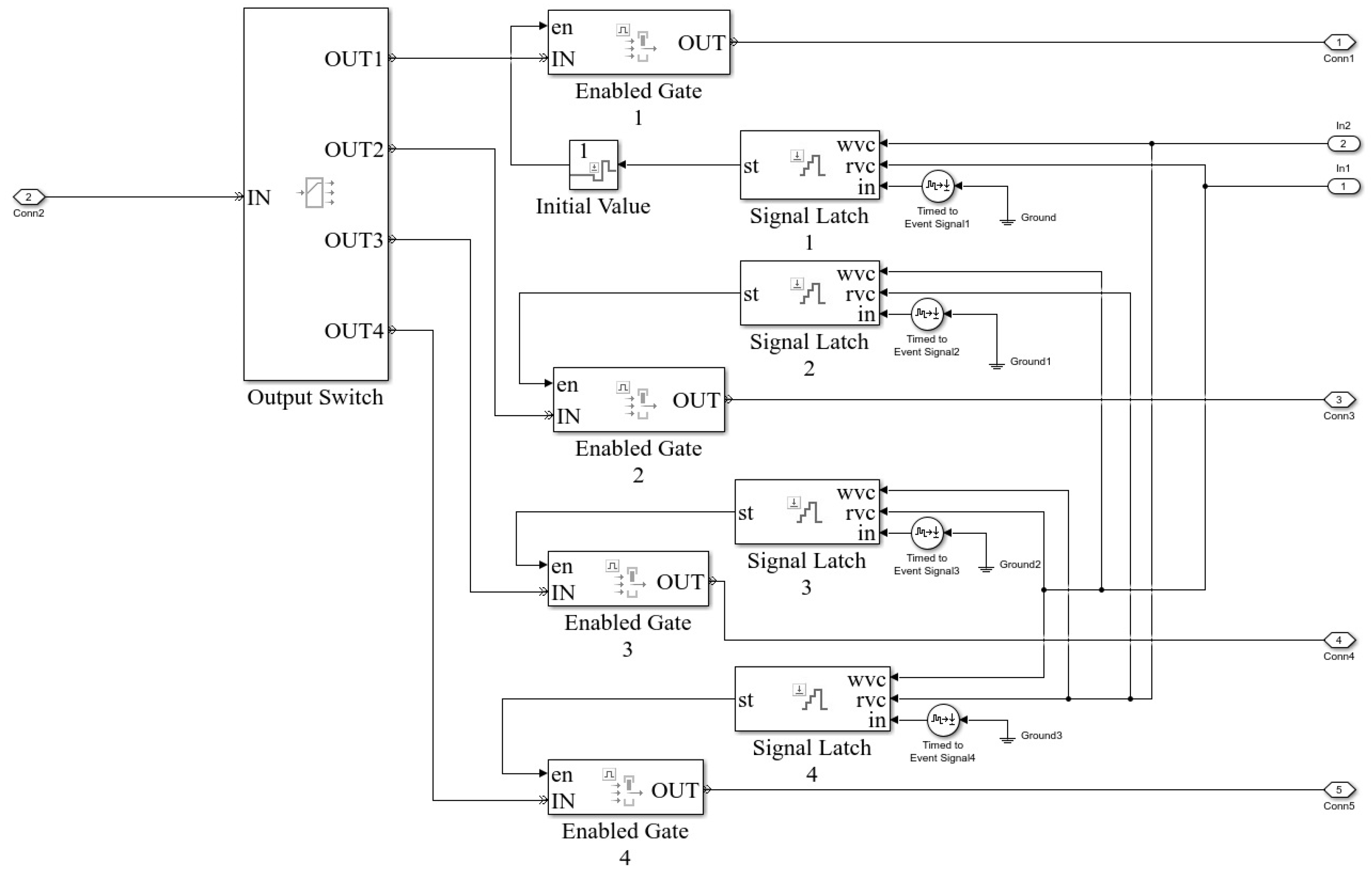
Figure 8. Building a sophisticated controller that monitors and synchronizes the switches’ operation is essential in this study. The four switches are connected internally with each other as well as with the controller. This connection helps to maximize the system reliability, security and minimize the drop packets in the network. The events enter the “output switch” block that has one input and four outputs at first and then forwards these to the receiver side. The function of that block is to forward the events to the available buffers of the switches. Each output of the “output switch block” is connected to a gate. These gates open only when the paths that are connected to them are ready to receive events. The gates are connected with a “signal latch” block that sends signals to the gates to open them after ensuring the availability of the connected switches.
The controller in this switch works to facilitate and smooth out the events travelling between the paths, as shown in
Figure 9. When the simulation runs, the “initial value block” sends an order to gate 1 to open and prepare to receive events from the input ports. The initial value block generates a random value before any signals hit its input port, then after the first signal enters, the output signal will be identical to incoming signals. The events are sent to the FIFO queue of switch 1 and then to the processor. Whenever the events leave the queue to the processor, the queue block sends a signal from (#d port) to (rvc port) to close the gate of the unavailable path. At the same time, it sends another signal to (wvc port) of the available path to open the gate and receive the events from input ports. In addition, after the processor of the master switch finished processing the events, it sends the events to the output ports and at the same time sends the signal from (#d port) to (wvc port) of the Single latch 1 to open the gate 1 and send single to (rvc port) to close the gate of the busy path to let the events forward to gate 1.
7. Conclusions
Ethernet switches in the electric power system are experiencing significant changes from traditional switches architectures to intelligent switches design that simplify and unify the transport packets in the network. This research investigated the issues of packet loss in the substation automation network. The loss occurs because the switch is unable to cope with the high volume of incoming traffic of the network. On the other hand, in the substation automation network, data delivery is crucial for proper functioning of the system. Consequently, a high-speed Ethernet network based on high-performance switches is required to ensure the system reliability and security. Only a high-quality network of IEC 61850 standard and GOOSE protocol of below 4 ms delay can cope that requirements.
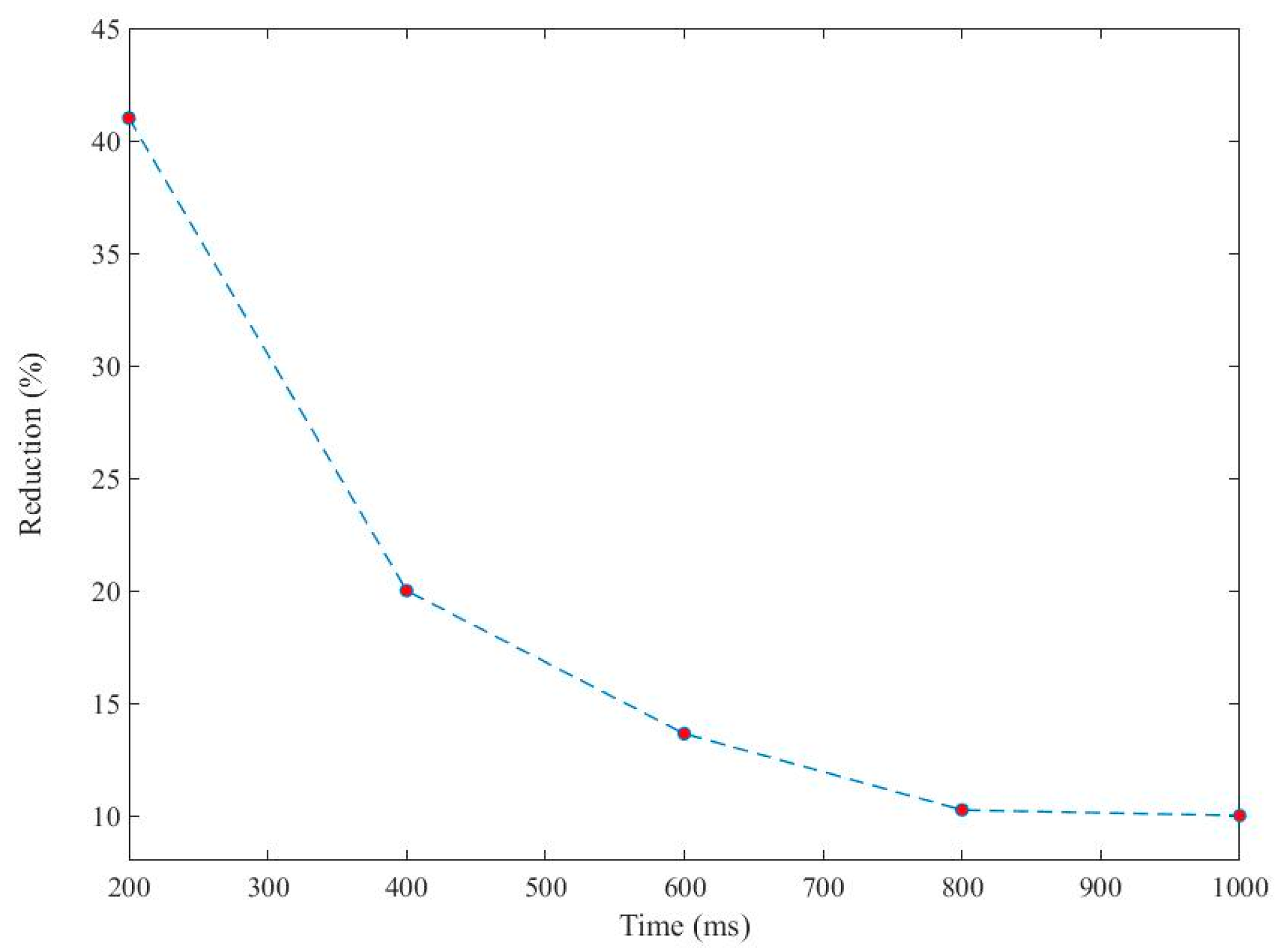
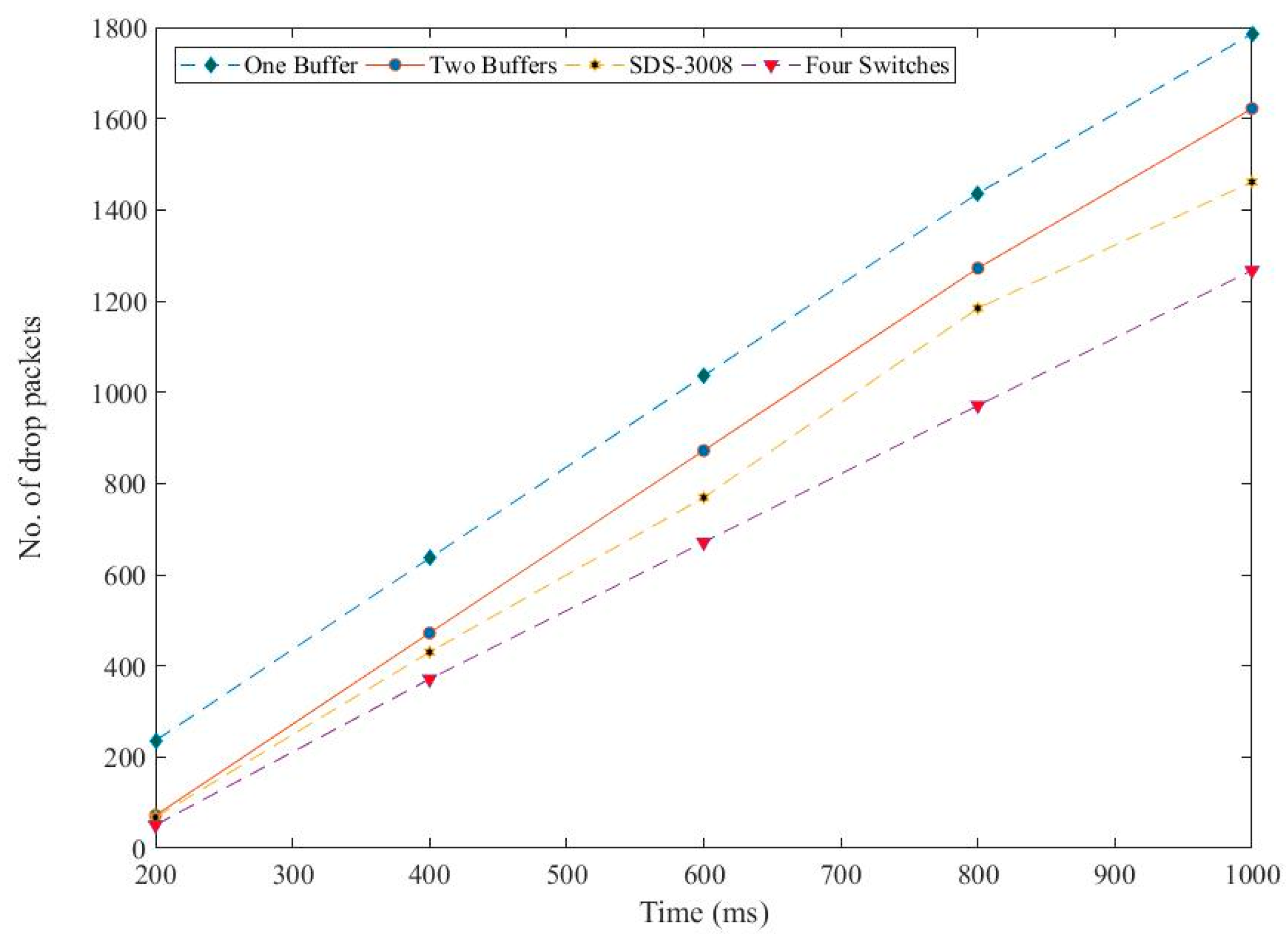
Investigations were carried out in this paper on various switch configurations and architectures to reduce the number of the drop packets. The investigation was implemented on the standard switch architecture with different buffer capacity, SDS-3008 and four switches architecture. The proposed switch architecture is integrated with an intelligent control mechanism that has the capability to distribute the load between the switches based on their availability. All the proposed architectures implemented by using MATLAB/SimEvent blocks and subsequently, all the simulations were carried out on this platform. Finally, the simulation results showed an outstanding performance of the four switches methodology as compared with other architectures.


