

Self-Unfolding Properties of Smart Grid-Reinforced Membrane Origami


1
Key Laboratory of Advanced Ship Materials and Mechanics, Harbin Engineering University, Harbin 150001, China
2
College of Aerospace and Civil Engineering, Harbin Engineering University, Harbin 150001, China
3
College of Mechanical and Electrical Engineering, Qingdao University, Qingdao 266071, China
*
Authors to whom correspondence should be addressed.
J. Compos. Sci. 2024, 8(2), 64; https://doi.org/10.3390/jcs8020064
Submission received: 8 November 2023
/
Revised: 3 February 2024
/
Accepted: 6 February 2024
/
Published: 7 February 2024
(This article belongs to the Special Issue Polymer Composites and Fibers, Volume II)
Abstract
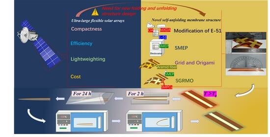
:Origami-based membrane structures have shown great potential to revolutionize the construction of deployable and lightweight space structures in the future. However, the efficient unfolding mechanism puts forward major challenges to the practical realization of space-deployable structures. Here, a smart grid-reinforced membrane origami (SGRMO) is presented. The unfolding action hinges upon the application of forces facilitated by shape memory polymer composites (SMPCs). Subsequent locking action ensues through the restoration of the initial rigidity, accomplished via cooling mechanisms. This novel structure achieves the required lightweight and functionality by employing the grid design concept and effectively reduces the decline in unfolding extent caused by irreversible plastic deformation at the crease. Its recovery properties, including unfolding angle, distance, and surface precision, are experimentally and analytically investigated under different conditions. The results indicate that the structure can be reliably unfolded into the predefined shapes. In the case of Miura-SGRMO, the optimal surface precision is attained when the angle-ψ registers at 30°. The results of this study are expected to serve as the design of ultra-large flexible solar arrays and deployable antenna structures.
1. Introduction
Owing to its inherent portability [1,2], scalability [3,4], and potential for miniaturization [5,6,7], origami technology has garnered significant attention within the context of configuring spaceborne membrane structures [8], as evidenced by its application in the design of deployable large-aperture membrane antennas [9], solar sails [10], and off-orbit drag sails [11]. The accomplishment of these applications hinges upon the unfolding strategies, ensuring both the efficient and precise deployment of the structure to its intended position and maintaining the imperative facet of structural lightness.
In the present landscape, space-deployable membrane structures are based on mechanical deployment [12,13], inflatable deployment [14], and elastic deployment [15]. These deployment methods are susceptible to constraints such as complexity, mechanical failures, and limitations related to weight and volume. In recent years, self-folding/unfolding structures and smart materials have been increasingly used in engineering applications [16,17,18,19,20]. Notably, the utilization of smart materials as the primary driving mechanism emerges as a transformative approach. Shape memory aromatic polyimides [21,22,23] are a kind of smart membrane structure that can be automatically deployed under given conditions. The membrane is completely covered with shape memory polymer. This not only increases the process cost but also fails to strike a balance between lightweight design and functionality. Inspired by the advanced grid structure [24,25] and variable configuration mesh structure [26,27,28] in terms of structural lightweight, load-bearing, and functionality, several researchers have employed grid structures to achieve improved control over the load-bearing capacity [29,30] and deformation behavior [31] of membrane structures with the advantage of adopting the idea of the discrete actuation of membranes. In a few studies, the shape memory material is applied only at the crease to drive the membrane structure to unfold [32,33,34], which improves the efficiency of structural development, but the configuration of the structure is not stable due to the weak stiffness of the membrane panel. It is difficult to use as a load-bearing structure. SMPCs have excellent mechanical properties [35,36,37], and they not only have shape memory function [38,39] but also have high stiffness [40] after cooling. The application of SMPCs at the crease and the panel may take into account the functionality and stability of the deployable structure.
Here, we propose a novel self-unfolding structure, named SGRMO. The structure consists of the membrane structure with a smart grid. The smart grid is bonded with membrane panel and across the crease, which can realize the expansion of structure by driving the crease open and further improve the panel stiffness. We apply this design idea to one-dimensional and Miura origami, which can be folded and self-unfolded. This research has the potential to provide new ideas for the design of space structures in the future.
2. Materials and Method
All chemicals were of analytical grade and purchased from commercial suppliers. There was no need for further purification.
2.1. Materials and Ratios
Shape memory polymer (SMP) was prepared through the modification of E-51 epoxy resin with the incorporation of n-octylamine (OA) and m-xylenolamine (MXDA). Further, SMP and aramid fiber were compounded to form SMPCs. The main products are provided in Table 1. The chemical structural formulas of the main products are listed in Figure 1.
The membrane was cut into long splines with lengths of 220 mm and widths of 70 mm; the thickness was 0.1 mm. Aramid fiber was cut to a length of 220 mm, a width of 9 mm, and a thickness of 1 mm.
OA belongs to the flexible curing agent classification. Its long molecular flexible alkyl chain can increase the toughness of the resin system and meet the subsequent folding requirements of the SMPCs. MXDA is an aromatic curing agent, which is used to form a three-dimensional lattice cross-linking structure in the system. This augmentation leads to an improvement in the overall rigidity of the resin system, ensuring that the smart grid remains stable after unfolding. The equation for preparing the SMP is shown in Equation (1).
- m—Required hardener content per 100 g of epoxy resin (g);
- A—Mass fraction;
- M—Molecular weight of amine (g/mol);
- nH—Number of active hydrogens in amine curing agents;
- K—Epoxy content.
E51 epoxy resin is a thermosetting polymer with an epoxy value of 0.51. The molecular weight of the OA is 129.24 g/mol. The number of active hydrogens is 2. For MXDA, the molecular weight is 136.19 g/mol. It has 4 active hydrogens. The mass percentage of SMP is 40%. The relationship between the quantity of SMPs and the aramid fiber can be expressed in the manner shown in Equation (2). Ultimately, we can calculate the weights required for E-51 epoxy resin, OA, and MXDA.
- mr—The amount of SMP (g);
- mf—The amount of aramid fiber (g).
2.2. Preparation of SGRMO
The preparation progress of the SGRMO is depicted in Figure 2. The detailed preparation process is described as follows:
Removing air bubbles: We immersed a measured quantity of E-51 epoxy resin in a water bath maintained at 70 °C for 30 min. This thermal treatment served to optimize the viscosity of the epoxy, enhanced its fluidity, and facilitated the expulsion of entrapped air bubbles.
Mixing and stirring: OA and MXDA were accurately mixed into the E-51 epoxy resin in predetermined proportions. These components were thoroughly stirred to ensure uniform mixing. The admixed solution was then transferred into an electric vacuum-drying oven for 10 min. This stage was pivotal in expelling the residual bubble in the SMP.
Bonding: We prepared the J-133c structural adhesive. The J-133c adhesive was made by mixing the epoxy resin (component A) and curing agent (component B) at a ratio of 2:1 by mass. Subsequently, we delicately applied this mixture to one side of the aramid fiber. The narrow stripe (here after named as the skeleton) was meticulously bonded to the membrane to ensure a robust and integrated connection.
Wetting and curing: The SMP was appropriately dripped onto the surface of the skeleton for comprehensive wetting. Subsequently, it was subjected to a heated cabinet dryer. The detailed curing procedures were divided into two steps: at 80 °C for 1 h in the first stage and at 120 °C for 2 h in the second stage.
2.3. Materials Characterization
The aramid fiber had a width of 9 mm and a thickness of 1 mm, the line density was 15.2 g/m, and the weave method was 2 × 2 twill weave.
The thickness of membrane was 0.1 mm. The elastic modulus and Poisson ratio of the membrane were, respectively, 2240 MPa and 0.34. The yield stress and yield strain of the membrane were, respectively, 69 MPa and 0.03, all of which were obtained by the manufacturer.
The Differential Scanning Calorimetry (DSC) of SMP was measured with DSC141, made by SETARM. The DSC instrument was calibrated using standard materials with known thermal properties. The resulting DSC thermogram provided information about phase transitions, such as the glass transition temperature Tg, and chemical reactions. The heating rate was 10 °C per minute, and the temperature range was 20–150 °C under nitrogen flux.
Dynamic mechanical thermal analyses (DMA) of SMPCs were measured with a TA-Q800, made by TA Instruments, to evaluate the storage modulus and loss factor of SMPCs. The Tg could be measured via the maximum peak of the loss factor. DMA tests were performed in a temperature range between 20 °C and 150 °C. The SMPCs were loaded via three-point bending. The loading frequencies were all 1 Hz.
2.4. Shape Memory Performance Test
The shape memory cycle and recirculation process are as follows:
- (a)
- Initially, the SGRMO was placed in an oven at an elevated temperature (Tg + 50 °C), and after one minute, the structure softened. Further, we folded the SGRMO and placed it between parallel plates with 15 mm apart.
- (b)
- Then, the SGRMO was placed in the room temperature condition (20 °C) with an invariant external load condition. We let it stand for one hour.
- (c)
- We removed the external load in the room temperature condition, and the SGRMO showed a slight rebound. We waited for 24 h to allow the structure to adequately rebound, until the shape remained stable.
- (d)
- Finally, we tested the SGRMO at a specific temperature (Tg + 10 °C), and the structure gradually unfolded into its initial state. After five minutes, the SGRMO was removed from the oven and kept at room temperature for one minute. After one minute, the shape could be fixed and stable.
The above is a complete shape memory cycle.
When the next shape memory cycle was performed, the SGRMO was handled as per the scheduled procedure (a), (b), (c) and (d). In this paper, we ignored the effect of gravity on the recovery performance due to the small density of the membrane and the small weight of the skeleton, which is about 3.8 g for the SGRMO.
The shape memory fixation ratio (Rf) reflected the ability of the structure to maintain a folded conformation. The shape memory recovery ratio (Rr) reflected the ability of the structure to recover to its initial conformation under the shape memory effect. Both were important indicators for shape memory performance. Rf and Rr can be calculated from Equations (3) and (4).
As shown in Figure 3, θfolded is the folded angle of the structure, and θfixed is the folded angle after removing the load. θresidual is the deviation angle between the angle after shape memory deformation and the initial state.
2.5. Finite Element Simulation
The ABAQUS, 2020 (Dassault, Paris, France) material model library is known to possess highly stable, fast, and accurate models. In this paper, the viscoelastic model of ABAQUS was used to simulate SGRMO [41]. The skeleton was considered to be a linear viscoelastic material [42,43], and the viscoelastic properties were represented in ABAQUS by the Prony series, which was fitted according to the data obtained from the DMA. The WLF parameters for the skeleton were referenced to empirical parameters [44].
2.5.1. Modeling
As shown in Figure 4, the model of the SGRMO was created with membrane dimensions of 70 mm × 220 mm × 0.1 mm and skeleton dimensions of 9 mm × 220 mm × 1 mm. The membrane and the skeleton were assembled with bonding constraints, which were considered to have no slip between them. To achieve a more precise numerical simulation of the SGRMO, it was imperative to ensure that the mesh density, calculation accuracy, and computational time were appropriately balanced and optimized. Based on the convergence test, the quadrilateral procession algorithm performed the final meshing, and the S4R-type mesh was selected for both the membrane and skeleton. The mesh size was about 0.5 mm away from the region of the crease because of the large bending deformation. To improve the calculation efficiency, the mesh size was about 8 mm away from the region of crease. Similarly, the mesh size of the skeleton near the crease was 0.075 mm, and the part away from the crease was about 2 mm. The area between the panel and the crease was set as a transition area.
We chose a key node on the upper surface at the center of the skeleton to describe the variation in its stress and strain during the folding and unfolding process. The stress and strain of this key node could reflect the maximum stress and maximum strain of SGRMO, which could be used to evaluate whether plastic deformation occurred.
The Miura origami is defined by the edges L1-L2-L3-L4, sector angle-ψ and angle-β, θ is the angle between L1 and the X-direction, representing the angle-ψ projection on the XY-plane at the geometric level, as shown in Figure 5a. According to the definition of the Miura configuration, the dimensions of the finite element model are L1 = L2 = L3 = L4 = 50 mm, the angle-ψ is 60°, and the angle-β is 80°. The finite element model of Miura-SGRMO was built in ABAQUS, as depicted in Figure 5b. The width of the grid was 9 mm, and its thickness was 1 mm. The global mesh size of Miura-SGRMO was set to 0.055 mm. The Miura configurations required the pre-incorporation of creases, the geometric shape and material properties were altered at the crease [45,46,47], and both the elasticity and plasticity of the crease needed to be considered. We utilized the rotational elastoplastic connectors to simulate the crease. The damping coefficient of the connectors was set at 0.2.
2.5.2. Simulation Steps
The boundary condition of the SGRMO is shown in Figure 6. The process consisted of four steps: (1) Heating and folding—the ambient temperature was meticulously set at 120 °C, and the bending load was imposed upon the structure. (2) Cooling—the temperature field was diminished from 120 °C to 20 °C, and the SGRMO remained in its folded state through the fixture. (3) Unloading—We removed the fixture and kept the temperature constant at 20 °C. (4) Heating and unfolding—The temperature was raised from 20 °C to 120 °C. When the ambient temperature reached Tg, the recovery of the SGRMO toward its initial shape began.
2.5.3. Viscoelastic Parameterization
Building upon the insights gained from the aforementioned experimental analyses, our objective was to construct a finite element model for the SGRMO. The skeleton was considered a linear viscoelastic material [42,43] and adopted the generalized Maxwell material model [48,49]. The viscosity ηi and modulus Ei were different in each Maxwell, and its physical theoretical model is shown in Figure 7. The generalized Maxwell model comprised a Hooke spring connected in parallel with multiple Maxwell model units.
As shown in Equation (5), the generalized Maxwell model expression in the time domain was as follows:
- —Young’s modulus relaxation function
- —Long-term modulus
- —Young’s relaxation modulus at time i
- —Relaxation time at moment i ()
We utilized finite element software (ABAQUS, 2020) for the viscoelastic simulation of materials [50,51], and the relaxation functions K(t) and G(t) were usually written in the form of Prony series [49], as shown in Equations (6) and (7).
Here, and represent the relaxation times for each component of the bulk and shear relaxation moduli in the Prony series. The viscoelastic parameters of the material were normalized, and then the normalized modulus was entered into ABAQUS to generate the Prony series.
2.6. Performance Estimation Method of Miura-SGRMO
To evaluate the unfolding behavior of Miura-SGRMO, we defined the distance of line segment O1O3 and O1O7 (shown in Figure 5a) as the unfolding lengths of Miura-SGRMO in the X direction and the Y direction, respectively, expressed by the parameters Sx and Sy, calculated from Equations (8) and (9), as follows:
where , and .
We further utilized the parameter ρ to evaluate the unfolding level of the model, which could be calculated using Equation (10), as follows: SX and SY represent the lengths of the X and Y directions in the simulation, while Sx and Sy represent the lengths of the X and Y directions via theoretical prediction.
We calculated the root mean square error of the Z-direction coordinates of the chosen key points between the simulation and the theory to evaluate the surface precision, as shown in Equation (11), as follows: zi and Zi represent the Z-direction coordinate, respectively obtained via the simulation and the theory. We selected 20 key points on each unit surface, as shown in Figure 8.
3. Results and Discussion
3.1. DSC Analysis of SMP
The weight of the aramid fiber webbing was 1.801 g via measurement. According to Equation (2), the required epoxy resin could be derived as 1.2 g. Based on Equation (1), we took the mass fraction for OA to be 0.65, and the mass fraction for MXDA was 0.35. The weights of the components are shown in Table 2. The SMP was tested via differential thermal analysis. As shown in Figure 9, the glass transition temperature of SMP was 47.61 °C.
3.2. Thermomechanical Properties of SMPCs
The SMPCs was prepared by using SMPs and aramid fibers. The DMA data of the SMPCs in this study are summarized in Figure 10. Based on the maximum value of the loss factor, we determined that Tg was 64.1 °C. This shows that the SMPCs prepared by applying SMPs to aramid fibers have higher glass transition temperatures than pure SMP.
3.3. Shape Memory Test Results
3.3.1. Shape Memory Performance of SGRMO
For the folding and recovery test, the SGRMO recovered to its initial state in about 70 s. As shown in Figure 11, when the SGRMO was removed from the fixture at room temperature, it had a slight rebound. This indicates that the skeleton provided sufficient ability for SGRMO to maintain its folded conformation. The recovery process of SGRMO was heated in an oven at 70 °C, and the SGRMO returned to its initial state after about 70 s.
3.3.2. Different Structural Forms
The effect of three skeleton bonding methods on the unfolding rate of the SGRMO was studied, as shown in Figure 12. The skeleton bonding methods included skeletons bonded on the folded valley side, skeletons bonded on the folded mountain side, and double skeletons bonded on the folded valley side. We prepared three samples for each group, and each point was the average of the recovery time of the three samples, and the error size was the maximum unfolding time and the minimum unfolding time, respectively. The results indicate that the skeleton position had little effect on the recovery rate.
Nevertheless, the unfolding time for the double-skeleton structure was significantly shorter than the time for the single-skeleton structure. This observation implies that the double-skeleton structure offers superior recovery performance.
3.3.3. Ambient Temperature
The shape memory recovery performance was sensitive to the ambient temperature. Our research focused on their recovery rate. Figure 13 shows the data obtained from the experiment, which illustrated the unfolding times for different ambient temperature conditions. The points and error lines have the same meaning as before. The unfolding rate of SGRMO significantly increased with an increase in the temperature. Firstly, the stiffness of the skeleton decreased with increasing temperature, thereby reducing the ability of SMPCs to fixed the shape of the membrane. Secondly, as the temperature increased, the molecular components within the skeleton became more active, thereby increasing the molecular mobility of the material. This molecular reorganization helps to return SGRMO to its original shape more quickly. In essence, the synergistic effect of these two factors together accelerated the more rapid return of SGRMO to its original shape at elevated temperatures.
3.3.4. Folding Frequency
The folding frequency of the SGRMO was also a significant factor for the deployable structure. Figure 14 shows the recovery time and the recovery angle for three samples of the SGRMO for different folding frequencies at 70 °C.
With the increase in the folding frequency, the unfolding time of the SGRMO exhibited a nonlinear pattern. The point at which recovery time was minimized may not occur in the first point, which suggested that the internal molecular chains of the SGRMO may be adjusted due to the need to accommodate external deformations when the structure was tested over shape memory cycles, and the minimal recovery time may have occurred after the first point. However, with the increased folding frequency, both the skeleton and the crease of the membrane experienced a significant level of aging. This aging was evident in the form of a weakened shape memory performance within the skeleton. Simultaneously, the membrane developed an elastic–plastic crease region. Importantly, at the crease, some of the external force work was converted into the plastic strain energy, which enhanced the membrane’s ability to resist recovery deformation. After the ninth or tenth folding frequency, debonding between the membrane and the skeleton was observed. Then, the recovery angle was essentially stable at a constant value. However, the first shape memory recovery angle was the largest.
To further investigate the effect of the folding frequency on the structural recovery properties, we also performed shape memory cycling tests at 100 °C and 120 °C. The impacts of the temperatures on the folding frequency for three groups of samples are shown in Figure 15. The trends for the recovery time at the three temperatures were almost the same, and the recovery time gradually increased with the increase in the folding frequency. When the ambient temperature became higher, the structure may have exhibited the debonding phenomenon earlier; this is because the glass transition temperature of J-133c is 100 °C, and when the ambient temperature was above 100 °C, the curing of the structural adhesive weakened, and the bond strength reduced.
We compared the shape memory performance of the SGRMO at 70 °C with those of other shape memory membrane structures for the first three folding frequencies, as is presented in Figure 16. SGRMO exhibited excellent shape memory performance, ensuring that the structure had an excellent shape memory recovery rate while maintaining a good shape memory fixation rate.
3.4. Finite Element Results
3.4.1. Elastic and Viscoelastic Parameters
The derivation of the Prony series was facilitated through the conducting of the relaxation experiments involving viscoelastic materials. Subsequently, the Prony series equation was meticulously tailored to conform to the experimental curves [27,54], and the parameters in the fitted Prony series curves were used directly in ABAQUS. The parameters of each discrete term of the Prony series were obtained, as shown in Table 3.
The WLF parameters to be entered into ABAQUS included Tg, C1, and C2. The Tg was measured via DMA testing. We chose the peak of the loss factor as the glass transition temperature, and C1 and C2 were taken as universal constants [44], as shown in Table 4.
As shown in Table 5, for the simulation of viscoelastic materials in ABAQUS, the storage modulus at the glass transition temperature in the DMA was taken as the elastic modulus of the SMPC.
The parameters of the membrane are shown in Table 6.
3.4.2. Shape Memory Recovery Process of SGRMO
The folding/unfolding simulation is shown in Figure 17. Stress concentration occurs in the crease region of the larger bending deformations. By comparing the experiment results, it can be found that the simulation effectively displays the folding and unfolding process of the structure.
The impact of the skeleton position on the unfolding behavior of the membrane was examined, taking into account the fact that the skeleton was positioned on the mountain side and valley side of the membrane. From Figure 18a, the movement tendency and unfolding angle of the SGRMO with two different positions for the skeleton were nearly synchronous.
In Figure 18b, we can see that there were more reliable fixation and better unfolding performances for the double-skeleton structure compared with the single-skeleton structure. In step Ⅲ, a smaller rebounding angle was found for the double-skeleton structure. In the fourth step, the angle of the double-skeleton structure reached 179.6° when the temperature rose above Tg. At the final moment, the double-skeleton structure had a larger recovery angle than the single-skeleton structure. Based on the results of the simulation, it could be concluded that for the single-skeleton structure, R1f = 97.75% and R1r = 98.80%. For the double-skeleton structure, R2f = 98.01% and R2r = 98.96%. It was consistent with the experimental conclusion that an increase in the number of skeletons enhanced the shape memory performance of SGRMO.
We plot the variation in stress and strain with temperature for the central element of the skeleton, as shown in Figure 19. In the first stage, the SGRMO was folded at 120 °C, and the stress and strains increased rapidly. In stage 2, due to the drop in temperature from 120 °C to 20 °C, the stress increases slowly when the structure was above the glass transition temperature. As the temperature dropped under the Tg, the structure was in a glassy state at this moment, and the stress increased more rapidly compared to the previous moment. The strain also decreased gradually due to the shrinkage effect. In the third stage, there was an abrupt change in the stress and strain as the external loads were removed. In the fourth stage, as the temperature rose, the stress decreased and the strain increased. When the ambient temperature was above Tg, the strain was rapidly released, and the relaxation of stresses occurred. Finally, the stress and strain were restored to the initial state.
3.4.3. Shape Memory Recovery Process of Miura-SGRMO
The folding/unfolding simulation of the Miura-SGRMO was accomplished and is depicted in Figure 20. The recovery property of the structure was not able to restore itself to its initial state due to the significant plastic deformation at the crease of the membrane. Meanwhile, the stress was basically concentrated in the crease area.
3.4.4. The Displacement of Miura-SGRMO
We described the change in the unfolding displacement as the angle β changed, as shown in Figure 21. The datapoints were chosen at every 10° interval in the allowed value range of β from 30° to 80°. The simulation results show that the configurations predicted using the theory (panel bending is not considered) agree well with the ones obtained via the simulation, which means that the panels of Miura-SGRMO have little bending deformation during the unfolding process, and the discrete skeleton significantly improves the stiffness of membrane panel.
We built five types of models with different Miura structural parameters, as shown in Table 7. Ori1–Ori5 had the same lengths, but the angle-ψ were 15°, 30°, 45°, 60°, and 75°, respectively.
Further, we analyzed the distance of X and Y directions when the angle-ψ of each model unfolded to 80° by using Equation (10), as shown in Table 8. The Miura-SGRMO had excellent unfolding performance, tolerance within 0.1%. The unfolding level of Ori3 was a little bit more than 100%. This was because recovery deformation of the grid structure and the elastic recovery of the membrane were different and coupled with each other, which together resulted in excessive bending of some areas of membrane away from the grid.
3.4.5. The Analysis of Surface Precision
It was necessary to organize an analysis of the structural surface precision to investigate the reliability of the operation. The surface precision values of Miura-SGRMO are shown in Figure 22. The membrane structure could be almost completely unfolded by the smart grid. Compared to the results from Ori1 to Ori5, it was noteworthy that the surface precision of Ori2 with the angle-ψ 30° was relatively high. This was because the larger the angle-ψ, the larger the size of the membrane, and the more difficult it was to flatten the shape of the unfolded surface. In contrast, when the angle-ψ was smaller than 30°, the size of the structure in the X-direction was much larger than that in the Y-direction, and a large distortion deformation occurred in the edge region away from the skeleton, which also increased the shape deviation of the structure.
4. Conclusions
In summary, we proposed a novel structure, named the smart grid reinforced membrane (SGRMO). We folded it according to a predetermined design scheme, and the programmable self-unfolding capability of the SGRMO was facilitated by the shape memory effect. The creative structure could be almost completely unfolded by the smart skeleton or grid. This suggests that the design idea of discretely driving the membrane structure was reasonable. Based on this work, the following conclusions were drawn:
- For SGRMO, the shape memory performance was almost the same for forward and backward folding, while increasing the number of smart skeletons improved the shape memory performance. Even after multiple shape memory cycles, SGRMO could guarantee excellent shape memory performance. The Rf of the SGRMO was maintained above 98.5% and Rr above 99% for the first three shape memory cycles.
- The ambient temperature exerted a profound influence on the recovery performance of SGRMO, where heightened temperatures correlated with an accelerated recovery process. Nevertheless, elevated temperatures precipitated earlier instances of debonding.
- The Miura-SGRMO unfolded without large bending deformations in the panel area. The unfolding process of SGRMO could be approximated as a rigid unfolding.
- Our investigation attested to the reliability of utilizing the grid structure for facilitating the unfolding process. The Miura-SGRMO unfolded with a high degree of unfolding distance and surface precision. At angle-ψ values of 15°, 30°, 45°, 60°, and 75°, respectively, our observations revealed that the optimal surface precision was attained at 30°, and the RMSE of this configuration stood at approximately 0.05 mm. However, the result was influenced by a dimensional effect, which must be thoroughly explored in subsequent research efforts.
Author Contributions
Conceptualization, H.H., Z.X., Q.T. and L.S.; methodology, H.H., Z.X. and Q.T.; software, H.H., Z.Y., K.Y. and L.S.; validation, Z.X. and K.Y.; investigation, H.H. and Z.Y.; resources, Z.X.; writing—original draft preparation, H.H.; writing—review and editing, Z.X., Q.T. and L.S.; supervision, Z.X. and L.S.; funding acquisition, Z.X. and Q.T. All authors have read and agreed to the published version of the manuscript.
Funding
This research was funded by the National Natural Science Foundation of China (Grant No. 12002101; No. 12202222).
Data Availability Statement
The data used to support the findings of this study are included within the article. Further data or information is available from the corresponding author upon request.
Conflicts of Interest
The authors declare no conflicts of interest.
References
- Turner, N.; Goodwine, B.; Sen, M. A review of origami applications in mechanical engineering. Proc. Inst. Mech. Eng. Part C J. Mech. Eng. Sci. 2016, 230, 2345–2362. [Google Scholar] [CrossRef]
- Mintchev, S.; Salerno, M.; Cherpillod, A.; Scaduto, S.; Paik, J. A portable three-degrees-of-freedom force feedback origami robot for human–robot interactions. Nat. Mach. Intell. 2019, 1, 584–593. [Google Scholar] [CrossRef]
- Peraza-Hernandez, E.A.; Hartl, D.J.; Malak, R.J., Jr.; Lagoudas, D.C. Origami-inspired active structures: A synthesis and review. Smart Mater. Struct. 2014, 23, 094001. [Google Scholar] [CrossRef]
- Wang, L.C.; Song, W.L.; Zhang, Y.J.; Qu, M.J.; Zhao, Z.; Chen, M.; Yang, Y.; Chen, H.; Fang, D. Active reconfigurable tristable square-twist origami. Adv. Funct. Mater. 2020, 30, 1909087. [Google Scholar] [CrossRef]
- Yan, Z.; Zhang, F.; Wang, J.; Liu, F.; Guo, X.; Nan, K.; Lin, Q.; Gao, M.; Xiao, D.; Shi, Y. Controlled mechanical buckling for origami-inspired construction of 3D microstructures in advanced materials. Adv. Funct. Mater. 2016, 26, 2629–2639. [Google Scholar] [CrossRef] [PubMed]
- Velvaluri, P.; Soor, A.; Plucinsky, P.; de Miranda, R.L.; James, R.D.; Quandt, E. Origami-inspired thin-film shape memory alloy devices. Sci. Rep. 2021, 11, 10988. [Google Scholar] [CrossRef] [PubMed]
- Pesaran, S.; Rafatmah, E.; Hemmateenejad, B. An all-in-one solid state thin-layer potentiometric sensor and biosensor based on three-dimensional origami paper microfluidics. Biosensors 2021, 11, 44. [Google Scholar] [CrossRef]
- Cai, J.; Ren, Z.; Ding, Y.; Deng, X.; Xu, Y.; Feng, J. Deployment simulation of foldable origami membrane structures. Aerosp. Sci. Technol. 2017, 67, 343–353. [Google Scholar] [CrossRef]
- Huang, J. The development of inflatable array antennas. IEEE Antennas Propag. Mag. 2001, 43, 44–50. [Google Scholar] [CrossRef]
- Murphy, D.M. Validation of a scalable solar sailcraft system. J. Spacecr. Rocket. 2007, 44, 797–808. [Google Scholar] [CrossRef]
- Harkness, P.; McRobb, M.; Lützkendorf, P.; Milligan, R.; Feeney, A.; Clark, C. Development status of AEOLDOS–A deorbit module for small satellites. Adv. Space Res. 2014, 54, 82–91. [Google Scholar] [CrossRef]
- Huang, H.; Guan, F.-L.; Pan, L.-L.; Xu, Y. Design and deploying study of a new petal-type deployable solid surface antenna. Acta Astronaut. 2018, 148, 99–110. [Google Scholar] [CrossRef]
- Lillie, C.; Dailey, D.; Polidan, R. Large aperture telescopes for launch with the Ares V launch vehicle. Acta Astronaut. 2010, 66, 374–381. [Google Scholar] [CrossRef]
- Häuplik-Meusburger, S.; Sommer, B.; Aguzzi, M. Inflatable technologies: Adaptability from dream to reality. Acta Astronaut. 2009, 65, 841–852. [Google Scholar] [CrossRef]
- Webb, D.; Hirsch, B.; Bach, V.; Sauder, J.F.; Bradford, S.; Thomson, M. Starshade mechanical architecture & technology effort. In Proceedings of the 3rd AIAA Spacecraft Structures Conference, AIAA SciTech, San Diego, CA, USA, 4–8 January 2016; pp. 1–11. [Google Scholar]
- Ze, Q.; Wu, S.; Nishikawa, J.; Dai, J.; Sun, Y.; Leanza, S.; Zemelka, C.; Novelino, L.S.; Paulino, G.H.; Zhao, R.R. Soft robotic origami crawler. Sci. Adv. 2022, 8, 7834. [Google Scholar] [CrossRef] [PubMed]
- Xu, B.; Wang, J.; Cai, C.; Xin, W.; Wei, L.; Yang, Q.; Peng, B.; Hu, Y.; Li, J.; Wang, X. Construction of Laminated Luminescent Solar Concentrator “Smart” Window Based on Thermoresponsive Polymer and Carbon Quantum Dots. Crystals 2022, 12, 1612. [Google Scholar] [CrossRef]
- Krysiak, Z.J.; Abdolmaleki, H.; Agarwala, S.; Stachewicz, U. Inkjet Printing of Electrodes on Electrospun Micro-and Nanofiber Hydrophobic Membranes for Flexible and Smart Textile Applications. Polymers 2022, 14, 5043. [Google Scholar] [CrossRef] [PubMed]
- Paik, J.K.; Wood, R.J. A bidirectional shape memory alloy folding actuator. Smart Mater. Struct. 2012, 21, 065013. [Google Scholar] [CrossRef]
- Liu, X.; Kang, S.; Zhang, D.; Li, Y.; Zhao, R.; Wu, C.; Cheng, Z.; Tao, Q.; Liu, Y. A liquid metal–based shape memory composite with the multi-responsive regulation of solid/liquid adhesion. Adv. Compos. Hybrid Mater. 2023, 6, 124. [Google Scholar] [CrossRef]
- Yang, Z.; Song, F.; Wang, Q.; Wang, T. Shape memory induced structural evolution of high performance copolyimides. J. Polym. Sci. Part A Polym. Chem. 2016, 54, 3858–3867. [Google Scholar] [CrossRef]
- Zi, Y.; Pei, D.; Wang, J.; Qi, S.; Tian, G.; Wu, D. High-Temperature-Induced Shape Memory Copolyimide. Polymers 2021, 13, 3222. [Google Scholar] [CrossRef] [PubMed]
- Sahoo, S.D.; Ravikumar, A.; Prasad, E. PVA–Polystyrene-Based Polymer Films with Water-Induced Shape-Memory Effect. Ind. Eng. Chem. Res. 2022, 61, 5797–5806. [Google Scholar] [CrossRef]
- Wang, M.; Dong, L.; Wu, J.; Shi, J.; Gao, Q.; Zhu, C.; Morikawa, H. Leaf-meridian bio-inspired nanofibrous electronics with uniform distributed microgrid and 3D multi-level structure for wearable applications. NPJ Flex. Electron. 2022, 6, 34. [Google Scholar] [CrossRef]
- Chao, Y.; Yi, H.; Cao, F.; Lu, S.; Ma, L. Experimental Analysis of Polycaprolactone High-Resolution Fused Deposition Manufacturing-Based Electric Field-Driven Jet Deposition. Crystals 2022, 12, 1660. [Google Scholar] [CrossRef]
- Wagner, M.; Chen, T.; Shea, K. Large shape transforming 4D auxetic structures. 3D Print. Addit. Manuf. 2017, 4, 133–142. [Google Scholar] [CrossRef]
- Tao, Q.; Wang, C.; Wang, K.; Xie, Z.; Tan, H. Mixed-mode bending of a smart reconfigurable lattice structure with bi-directional corrugated core. Int. J. Mech. Sci. 2020, 185, 105848. [Google Scholar] [CrossRef]
- Zhang, Y.; Tao, Q.; Liu, Y.; Wang, C. Mesh/membrane composite with superior mechanical performance: A deep learning-based design. Compos. Sci. Technol. 2022, 230, 109735. [Google Scholar] [CrossRef]
- Pagitz, M.; Pellegrino, S. Buckling pressure of "pumpkin" balloons. Int. J. Solids Struct. 2007, 44, 6963–6986. [Google Scholar] [CrossRef]
- Saito, Y.; Iijima, I.; Matsuzaka, Y.; Matsushima, K.; Tanaka, S.; Kajiwara, K.; Shimadu, S. Development of a super-pressure balloon with a diamond-shaped net. Adv. Space Res. 2014, 54, 1525–1529. [Google Scholar] [CrossRef]
- Chen, T.; Bilal, O.R.; Lang, R.; Daraio, C.; Shea, K. Autonomous deployment of a solar panel using elastic origami and distributed shape-memory-polymer actuators. Phys. Rev. Appl. 2019, 11, 064069. [Google Scholar] [CrossRef]
- Tolley, M.T.; Felton, S.M.; Miyashita, S.; Aukes, D.; Rus, D.; Wood, R.J. Self-folding origami: Shape memory composites activated by uniform heating. Smart Mater. Struct. 2014, 23, 094006. [Google Scholar] [CrossRef]
- Mao, Y.; Yu, K.; Isakov, M.S.; Wu, J.; Dunn, M.L.; Jerry Qi, H. Sequential self-folding structures by 3D printed digital shape memory polymers. Sci. Rep. 2015, 5, 13616. [Google Scholar] [CrossRef]
- Liu, Y.; Shaw, B.; Dickey, M.D.; Genzer, J. Sequential self-folding of polymer sheets. Sci. Adv. 2017, 3, e1602417. [Google Scholar] [CrossRef] [PubMed]
- Madbouly, S.A.; Lendlein, A. Shape-memory polymer composites. Shape-Mem. Polym. 2010, 226, 41–95. [Google Scholar]
- Qi, H.J.; Nguyen, T.D.; Castro, F.; Yakacki, C.M.; Shandas, R. Finite deformation thermo-mechanical behavior of thermally induced shape memory polymers. J. Mech. Phys. Solids 2008, 56, 1730–1751. [Google Scholar] [CrossRef]
- Leng, J.; Lan, X.; Liu, Y.; Du, S. Shape-memory polymers and their composites: Stimulus methods and applications. Prog. Mater. Sci. 2011, 56, 1077–1135. [Google Scholar] [CrossRef]
- Emmanuel, K.; Jeewantha, L.; Herath, H.; Epaarachchi, J.; Aravinthan, T. Shape memory polymer composite circular and square hollow members for deployable structures. Compos. Part A Appl. Sci. Manuf. 2023, 171, 107559. [Google Scholar] [CrossRef]
- Guo, M.; Zhang, Y.; Huang, C.; Zhao, X.; Yan, X.-P.; Huang, Y.; Li, L.; Liu, T. Shape memory polyimide aerogel composites with high programming temperatures and exceptional shape recovery capability. Compos. Part A Appl. Sci. Manuf. 2023, 174, 107717. [Google Scholar] [CrossRef]
- Xia, Y.; He, Y.; Zhang, F.; Liu, Y.; Leng, J. A review of shape memory polymers and composites: Mechanisms, materials, and applications. Adv. Mater. 2021, 33, 2000713. [Google Scholar] [CrossRef]
- Cui, F.; Moon, S.; Rao, I.J. Modeling the viscoelastic behavior of amorphous shape memory polymers at an elevated temperature. Fluids 2016, 1, 15. [Google Scholar] [CrossRef]
- Zheng, X.; Zhou, B.; Xue, S. A viscoelastic-plastic constitutive model of shape memory polymer. J. Mech. 2019, 35, 601–611. [Google Scholar] [CrossRef]
- Duan, H.; Gu, J.; Zeng, H.; Khatibi, A.A.; Sun, H. A thermoviscoelastic finite deformation constitutive model based on dual relaxation mechanisms for amorphous shape memory polymers. Int. J. Smart Nano Mater. 2023, 14, 243–264. [Google Scholar] [CrossRef]
- Shangguan, Y.; Chen, F.; Jia, E.; Lin, Y.; Hu, J.; Zheng, Q. New insight into time-temperature correlation for polymer relaxations ranging from secondary relaxation to terminal flow: Application of a universal and developed WLF equation. Polymers 2017, 9, 567. [Google Scholar] [CrossRef] [PubMed]
- Beex, L.; Peerlings, R. An experimental and computational study of laminated paperboard creasing and folding. Int. J. Solids Struct. 2009, 46, 4192–4207. [Google Scholar] [CrossRef]
- Xia, Z.; Wang, C.; Tan, H. Elastoplastic folding behavior of membrane ribbon based on plane strain beam theory. Int. J. Solids Struct. 2018, 143, 167–174. [Google Scholar] [CrossRef]
- Xia, Z.; Wang, C.; Tan, H.F. Quasi-static unfolding mechanics of a creased membrane based on a finite deformation crease-beam model. Int. J. Solids Struct. 2020, 207, 104–112. [Google Scholar] [CrossRef]
- Jarrah, H.R.; Zolfagharian, A.; Hedayati, R.; Serjouei, A.; Bodaghi, M. Nonlinear finite element modelling of thermo-visco-plastic styrene and polyurethane shape memory polymer foams. Actuators 2021, 10, 46. [Google Scholar] [CrossRef]
- Gu, J.; Sun, H.; Fang, J.; Fang, C.; Xu, Z. A unified modeling approach for amorphous shape memory polymers and shape memory polymer based syntactic foam. Polym. Adv. Technol. 2016, 27, 1237–1245. [Google Scholar] [CrossRef]
- Battini, D.; Avanzini, A.; Pandini, S.; Bignotti, F. Modeling approach and finite element analyses of a shape memory epoxy-based material. In Proceedings of the XXIV AIMETA Conference 2019, Rome, Italy, 15–19 September 2019; pp. 689–704. [Google Scholar]
- Ghobadi, E.; Shutov, A.; Steeb, H. Parameter identification and validation of shape-memory polymers within the framework of finite strain viscoelasticity. Materials 2021, 14, 2049. [Google Scholar] [CrossRef]
- Wang, Q.; Bai, Y.; Chen, Y.; Ju, J.; Zheng, F.; Wang, T. High performance shape memory polyimides based on π–π interactions. J. Mater. Chem. A 2015, 3, 352–359. [Google Scholar] [CrossRef]
- Zarghami Dehaghani, M.; Kaffashi, B.; Haponiuk, J.T.; Piszczyk, L. Shape memory thin films of Polyurethane: Does graphene content affect the recovery behavior of Polyurethane nanocomposites? Polym. Compos. 2020, 41, 3376–3388. [Google Scholar] [CrossRef]
- Tobushi, H.; Hashimoto, T.; Hayashi, S.; Yamada, E. Thermomechanical constitutive modeling in shape memory polymer of polyurethane series. J. Intell. Mater. Syst. Struct. 1997, 8, 711–718. [Google Scholar] [CrossRef]
Figure 1.
Chemical structural formulas of E-51 epoxy resin, OA, and MXDA.

Figure 2.
Preparation of the SGRMO.

Figure 3.
Angle measurement method.

Figure 4.
Finite element model of SGRMO.

Figure 5.
Miura-SGRMO: (a) parameters of Miura Origami; (b) finite element model, where the brown area represents the membrane, the yellow area is grid structure, and the SMPCs and the cell surfaces of the membrane are bonded.
Figure 5.
Miura-SGRMO: (a) parameters of Miura Origami; (b) finite element model, where the brown area represents the membrane, the yellow area is grid structure, and the SMPCs and the cell surfaces of the membrane are bonded.

Figure 6.
This shape memory cycle consists of two hot stages (red background) and two cold stages (blue background). The red background represents the high-temperature field, and the blue background represents the low-temperature field.
Figure 6.
This shape memory cycle consists of two hot stages (red background) and two cold stages (blue background). The red background represents the high-temperature field, and the blue background represents the low-temperature field.

Figure 7.
The generalized Maxwell model.

Figure 8.
Description of key points for the surface precision estimation of Miura-SGRMO.

Figure 9.
DSC profiles of SMP.

Figure 10.
DMA test curve of SMPCs.

Figure 11.
Shape memory test: (a) folding state under an external load; (b) temporary shape; (c–e) shape recovery when heating at 70 °C; (f) initial state.
Figure 11.
Shape memory test: (a) folding state under an external load; (b) temporary shape; (c–e) shape recovery when heating at 70 °C; (f) initial state.

Figure 12.
The effect of different structure forms on the recovery rate.

Figure 13.
The effects of different ambient temperatures on the recovery rate.

Figure 14.
Recovery times and angles for different fold frequencies.

Figure 15.
Recovery time for fold frequency at different temperatures.

Figure 16.
Shape memory properties in the first three folding frequencies with different designs, SMPI [21], 6FDA/ODPA-ODA-37 PI [22], 34ODA-BPDA PI [52], PU-0.25 [53]: (a) the relationship between the fold frequency and shape memory fixation rate; (b) the relationship between the fold frequency and shape memory recovery rate.

Figure 17.
Shape memory process for simulation: (a) folding state under external load; (b) temporary shape; (c) middle state when heating at 70 °C; (d) initial state.
Figure 17.
Shape memory process for simulation: (a) folding state under external load; (b) temporary shape; (c) middle state when heating at 70 °C; (d) initial state.

Figure 18.
The variation law of the unfolding angle with the analysis step: (a) skeleton positions; (b) skeleton numbers.
Figure 18.
The variation law of the unfolding angle with the analysis step: (a) skeleton positions; (b) skeleton numbers.

Figure 19.
Plot of the axial direction stress and strain versus temperature in the simulation: (a) the curve of stress versus temperature; (b) the curve of strain versus temperature.
Figure 19.
Plot of the axial direction stress and strain versus temperature in the simulation: (a) the curve of stress versus temperature; (b) the curve of strain versus temperature.

Figure 20.
Shape memory process for simulation of the Miura-SGRMO.

Figure 21.
The displacements of Miura-SGRMO during the recovery process.

Figure 22.
Surface precisions of Miura-SGRMO with different angle-ψ values.


Table 1.
Product and manufacturer.
| Product | Manufacturer (of a Product) |
|---|---|
| E-51 epoxy resin | Shandong Yousuo Chemical Co., LTD, Linyi, China |
| OA | Shanghai Aladdin Bio-Chem Technology Co., LTD, Shanghai, China |
| MXDA | Shanghai Aladdin Bio-Chem Technology Co., LTD |
| J-133c-structural adhesive (A/B) | Institute of Petrochemistry, Heilongjiang Academy of Sciences, Harbin, China |
| Acetone | Shanghai Aladdin Bio-Chem Technology Co., LTD |
| Anhydrous ethanol | Shanghai Aladdin Bio-Chem Technology Co., LTD |
| Aramid fiber | Dongguan Shengmao Special Weaving Technology Co., LTD, Dongguan, China |
| Membrane | Guangdong Chenghao Plastic Industry Co., LTD, Dongguan, China |
Table 2.
Weight of the SMP.
| Product | Weight (g) |
|---|---|
| E-51 epoxy resin | 1.200 |
| OA | 0.257 |
| MXDA | 0.073 |
Table 3.
Relaxation modulus and relaxation time for each level in the Prony series.
| Relative Shear Modulus | Relative Bulk Modulus | Relaxation Time | |
|---|---|---|---|
| 1 | 0.384 | 0 | 0.017 |
| 2 | 0.272 | 0 | 0.09 |
| 3 | 0.105 | 0 | 1 |
| 4 | 0.031 | 0 | 12 |
| 5 | 0.207 | 0 | 56 |
| Total | 0.999 |
Table 4.
Constant of WLF equation.
| Tg | C1 | C2 |
|---|---|---|
| 64.1 °C | 17.4 | 51.6 |
Table 5.
Linear elasticity parameters for SMPCs.
| Elastic Modulus (mPa) | Poisson | Coefficient of Thermal Expansion (CTE) (1/°C) |
|---|---|---|
| 2060 | 0.4 | 6.47 × 10⁻⁵ |
Table 6.
Linear elasticity parameters for membrane.
| Elastic Modulus (mPa) | Poisson | Yield Strain | Yield Stress (mPa) |
|---|---|---|---|
| 2240 | 0.34 | 0.03 | 69 |
Table 7.
Geometric parameters of the Miura-Origami.
| Model | L1-L2-L3-L4 (mm) | ψ (°) |
|---|---|---|
| Ori1 | 50-50-50-50 | 15 |
| Ori2 | 50-50-50-50 | 30 |
| Ori3 | 50-50-50-50 | 45 |
| Ori4 | 50-50-50-50 | 60 |
| Ori5 | 50-50-50-50 | 75 |
Table 8.
Unfolding distance and degree of unfolding for each model.
| Model | X-Displacement | Y-Displacement | ρ |
|---|---|---|---|
| Ori1 | 1.0523 mm | 19.401 mm | 98.93% |
| Ori2 | 7.1401 mm | 47.437 mm | 99.96% |
| Ori3 | 18.350 mm | 69.681 mm | 100.05% |
| Ori4 | 35.347 mm | 85.945 mm | 99.92% |
| Ori5 | 57.701 mm | 95.337 mm | 99.95% |
Disclaimer/Publisher’s Note: The statements, opinions and data contained in all publications are solely those of the individual author(s) and contributor(s) and not of MDPI and/or the editor(s). MDPI and/or the editor(s) disclaim responsibility for any injury to people or property resulting from any ideas, methods, instructions or products referred to in the content. |
© 2024 by the authors. Licensee MDPI, Basel, Switzerland. This article is an open access article distributed under the terms and conditions of the Creative Commons Attribution (CC BY) license (https://creativecommons.org/licenses/by/4.0/).
Share and Cite
MDPI and ACS Style
Hu, H.; Xia, Z.; Tao, Q.; Ye, Z.; Yuan, K.; Song, L. Self-Unfolding Properties of Smart Grid-Reinforced Membrane Origami. J. Compos. Sci. 2024, 8, 64. https://doi.org/10.3390/jcs8020064
AMA Style
Hu H, Xia Z, Tao Q, Ye Z, Yuan K, Song L. Self-Unfolding Properties of Smart Grid-Reinforced Membrane Origami. Journal of Composites Science. 2024; 8(2):64. https://doi.org/10.3390/jcs8020064
Chicago/Turabian StyleHu, Haotian, Zhenmeng Xia, Qiang Tao, Zixin Ye, Kaifeng Yuan, and Leying Song. 2024. "Self-Unfolding Properties of Smart Grid-Reinforced Membrane Origami" Journal of Composites Science 8, no. 2: 64. https://doi.org/10.3390/jcs8020064