Article

Fabrication and Characterization of Piezoelectric PEO/SF/BaTiO3 Scaffolds for Cardiac Tissue Engineering

by
Abdelrahman K. A. Khalil
1,
Hassan Fouad
2,*,
Abdalla Abdal-hay
3,4,
Nasser M. Abd El-salam
2 and
Khalil Abdelrazek Khalil
5,*
1
Graduated from the Mechanical Engineering Department, College of Engineering, King Saud University, Riyadh 12372, Saudi Arabia
2
Applied Medical Science Department, Community College, King Saud University, Riyadh 12642, Saudi Arabia
3
School of Dentistry, University of Queensland, Herston Campus, St. Lucia, QLD 4072, Australia
4
Department of Mechanical Engineering, Faculty of Engineering, South Valley University, Qena 83523, Egypt
5
Department of Mechanical and Nuclear Engineering, College of Engineering, University of Sharjah, Sharjah P.O. Box 27272, United Arab Emirates
*
Authors to whom correspondence should be addressed.
J. Compos. Sci. 2023, 7(5), 200; https://doi.org/10.3390/jcs7050200
Submission received: 20 March 2023 / Revised: 7 May 2023 / Accepted: 12 May 2023 / Published: 16 May 2023
(This article belongs to the Special Issue Functional Additives for Bio-Based Advanced Composites)

Abstract

:
The existence of an intrinsic electrical platform responsible for the formation and transmission of impulses is essential, especially in cardiac tissue. However, most cardiac tissue made from biodegradable polymeric materials lacks conductive characteristics; this delays regional conduction, potentially causing arrhythmias. This study proposes a conductive polyethylene oxide (PEO)/silk fibroin (SF)-based material conjugated with conductive nanoparticles as a cardiac patch to fix any infarcted heart part. A new composite of PEO/15 wt%SF/0.2 wt%BaTiO3 was prepared and characterized in vitro. The obtained patches were characterized by conventional Bragg-platinum-conductive action (XRD), FTIR spectroscopy, Raman spectra, and thermogravimetric analysis. A PiezoTester device was used to evaluate the piezoelectric properties. The produced samples of 500 μm thickness were assessed in tapping mode. The applied load was selected to be as low as possible, and the frequencies were adjusted to simulate the heartbeats, ranging from 10 to 100 Hz. The results showed that a maximum of around 1100 mV was obtained at a load of 20 N. A maximum of about 80 mV was received at an applied force of 1 N and a frequency of 100 Hz, which matches the electricity generated by the human heart. The cytotoxicity effect of prepared films was tested against AC16 cells using microculture tetrazolium assay (MTT). The pristine PEO cell viability either was not affected by adding SF or slightly decreased. However, the cell viability dramatically increased by adding BaTiO3 to the PEO/SF composites. The confocal microscope images proved that the cells showed a spread morphology. The cells adhered to the PEO membranes and demonstrated a well-spread morphology. Overall, our study suggests that the PEO/SF/BaTiO3 composite can be a promising cardiac patch material for repairing infarcted heart tissue, as it is conductive, has good mechanical properties, and is biocompatible.

1. Introduction

Over the last few decades, it has been believed that the mammalian heart cannot regenerate and does not contain any endogenous regenerative capacity that can be activated or enhanced. Current treatments aim to prevent cardiomyocyte (CM) death, as organ transplantation is the only therapy for replacing damaged or lost cardiac tissue [1,2]. Unfortunately, there are not enough heart donors to fulfill increasing demands [3,4,5], and this therapy is complicated [6]. Therefore, there is a significant focus on precautionary cardiovascular remedies, with monitoring and targeting risk factors and the addition of antiplatelet therapy [7,8,9,10]. Considerable progress has been made to reduce the damage caused during the myocardial infarction (MI) acute phase.
The efforts resulted in the introduction of reperfusion treatment with thrombolysis “Fibrinolytic Therapy Trialists” (FTT) [11,12]. Acute percutaneous coronary intervention with antiplatelet agents, such as glycoprotein IIb/IIIa inhibitors, has also been introduced [13]. Despite these developments, the prevalence of cardiomyocyte losses has increased in the last few decades [14]. Therefore, it is also mandatory to further improve therapies for the acute phase of MI. The commonly used treatment is cardiac transplantation. Unfortunately, cardiac transplantation treatment has high risks of rejection and infection, with the possible complication of immunosuppressive drugs. Another clinical solution is to use muscle from a patient’s body to assist his injured heart [15]. However, early attempts using skeletal muscle failed.
Accordingly, cardiac tissue engineering (CTE) is the most popular strategy to reconstruct, reintegrate, and produce a bioactive scaffold with anisotropic functions. The anisotropic functions help in cell guidance and orientation and promote vascularization. The 3D-CTE scaffolds should have interconnecting pores structures of a suitable size to favor tissue integration and controlled biodegradability or/and bioresorbability. They should also have no adverse response, be easily fabricated into different shapes and dimensions, and have superior electro-mechanical properties to integrate with the host tissues. Moreover, its architecture defines the ultimate form of assisted cell formation [16,17]. The significance of using CTE can be highlighted in several ways. Heart transplantation is a viable treatment option for end-stage heart failure that addresses the shortage of donor hearts, but the demand for donor hearts exceeds the supply. CTE provides an alternative source of heart tissue, which can potentially address the shortage of donor hearts. CTE can provide a scaffold for cells to grow and differentiate into functional heart tissues, enhancing the potential for cardiac regeneration. Moreover, CTE can provide a platform for developing personalized medicine, allowing for the testing of drugs and treatments on patient-specific heart tissues. This approach could improve the efficacy and safety of treatments, particularly in cases where there is variability in individual responses to medicine.
The main challenge in CTE is the physical, electrical, and mechanical properties that match the natural cells. The tissue-engineering scaffold must provide multi-functional properties, such as good physiochemical properties, superior mechanical and electrical integrity, etc. In particular, the CTE scaffolds should provide mechanical integrity, deliver inductive or/and conductive molecules or cells to the treated site, and offer clues to precisely mimic the structure and properties of newly created tissue [18,19,20,21,22,23,24]. In this context, PEO is an appealing biomaterial for CTE. PEO polymer has an extensive range of absorbability and degradability. PEO polymer exhibits suitable stiffness and excellent mechanical properties that are compatible with soft tissues [25]. However, the bioactivity of PEO polymer is relatively low, and blending with natural polymers such as SF is usually required. Incorporating natural polymer (SF) in PEO is one of the most promising strategies for creating anisotropic architecture for engineering cardiac tissue [26,27]. Thus, recreating the anisotropic architecture of native cardiac tissues in bioengineered scaffolds is essential.
Moreover, investigating the electrical conductivity of the suggested PEO/SF samples to determine how the 3D scaffold can provide the electrical properties to mimic the heart muscle cells’ electrical integrated functions is essential. The heart muscle cells usually generate electrical signals, which set the intrinsic cardiac rhythm. SF has excellent biocompatibility and superior mechanical properties [28]. Many researchers have studied the performance of the silk-based material on cultures of human cells and reported that SF has significantly favorable effects on cell performance, such as attachment, growth factors, proliferation, and differentiated functions [29,30,31]. However, the degradation rate was shown to be very slow and not controllable during implantation. According to the US Pharmacopeia, silk is not considered a degradable biomaterial because it retains over fifty percent of its tensile integrity sixty days after implantation in animal models. Thus, adding it to a highly biodegradable polymer such as PEO will widen the use of SF in many biomedical applications.
Furthermore, the piezoelectric characteristics of the PEO/SF can be highly improved by adding magnetic nanoparticles with specific piezoelectric properties. SF transforms from silk I to silk II; thus, the phase transformation limits the dipole. Adding piezoelectric nanoparticles will enhance the dipole characteristics, output voltage, and piezoelectrical characteristics of the newly designed PEO/SF composite. Moreover, integrating nanoparticle features has promoted cardiac tissue repair and regeneration.
Constructing a scaffold composed of PEO and SF with tailored electro-mechanical properties would offer the proper conditions for attachment, signaling (electrical coupling), and differentiation of cardiac cells. BaTiO3 nanoparticles have been used to enhance the piezoelectric performance of the PEO/SF biocomposites. This work used biodegradable and highly biocompatible PEO/SF/BaTiO3 composite film fabricated by sol–gel casting technology. The PEO/SF/BaTiO3 composite film was characterized. Cell interaction with the produced films was studied using MTI cells through adhesion and proliferation tests.

2. Materials and Methods

2.1. PEO/SF/BaTiO3 Scaffold Preparation

A polyethylene oxide (PEO, MW 100,000, Sigma Aldrich, St. Louis, MO, USA) powder was used as received. A total of 12 wt.% of PEO was dissolved in 88 wt.% of a mixture of deionized water and ethanol (80 wt.% of deionized (DI) water and 20 wt.% of ethanol) to prepare the PEO solution. The solution was sealed and stirred at a constant speed of 250 RPM and kept at 80 °C until uniform solution density was obtained. A 5% (SF) solution purchased from advanced biomatrix (Advanced BioMatrix, Inc. Carlsbad, CA, USA) was used as received. The SF was kept at −70 °C on the day of delivery until being used. At the time of processing, the SF was thawed overnight at a temperature ranging from 2 to 4 °C until the solution became transparent with a low viscosity. Then, the SF solution was added to the PEO solution to form a PEO/SF blend. Based on a previous study [32], the PEO/15 wt.% SF blends were selected to be the composite to continue the experimental plan. BaTiO3 particles were purchased by Nanostructured & Amorphous Materials, Inc. (Houston, TX, USA), with an average size of 100 nm. A total of 0.2 wt.% BaTiO3 particles were added to the PEO/15 wt. The wt% of BaTiO3 was selected based on a previous study [32]. Finally, 90 mL of the blend solution was cast into plates following the doctor blade technique and left to dry in a fume hood at 30 °C for 48 h and then under vacuum for an additional 48 h. A thin film of less than 500 µm thickness was obtained. A schematic diagram of the thin-film processing and characterization is shown in Figure 1.

2.2. Characterization of the Thin Film

Fourier transformation infrared (FTIR) spectroscopy of the produced samples was conducted at reflection mode by a spectrophotometer model Thermo Nicolet 6700 Fourier transform IR spectrometer in the range of 4000–500 cm−1 with an accuracy of ±0.09 cm−1. The KBr disc method was used. The produced thin films were characterized by conventional Bragg-platinum-conductive action (XRD) to evaluate the structure of the casted thin films. The XRD was conducted to analyze the phase and crystallinity using a Rigaku X-ray diffractometer (Rigaku Co., Tokyo, Japan) with Cu Kα (λ = 1.54056 Å). Additionally, 2θ angles from 5° to 80° were used. A spectrometer (JY H800UV, Renishaw, London, UK) with an optical microscope was used to collect Raman spectra at room temperature with a radiation wavelength of 532 nm. Thermal analysis using thermogravimetric analysis (TGA) and deferential scanning calorimetry (DSC) (DSC; NETZSCH DSC 200PC, Jubiter, Waldkraiburg, Germany) at a heating rate of 10 °C/min was used to assess the thin films’ thermal characteristics.
A PiezoTester device assembled in our lab was used to evaluate the piezoelectric properties of the prepared PEO/15 wt% SF/0.2 wt%BaTiO3 samples. Cast film samples of about 500 μm thickness were placed in a container under a cam-connected hammer, as shown in the schematic diagram in Figure 1. The PiezoTester device applied the specific dynamic force with different frequencies to the prepared sample. The applied load was selected to be as low as possible, and the frequencies were adjusted to simulate heartbeats, ranging from 10 to 100 Hz. More details about the tester can be found in our previous work [32]. A RIGOL DS4012 model digital oscilloscope (Batronix GmbH &Co. KG, Preetz, Germany) was connected to the assembled samples and used to measure the output voltage. Moreover, the piezoelectric output voltage of the load cell monitored the value of the frequency and the applied alternative force.
The cytotoxicity effect of prepared films was tested against AC16 cells using MTT. AC16 cells (the human AC16 cell line was purchased from Sigma-Aldrich (St. Louis, MS, USA)) were seeded into 96-well plates with 10,000 cell/well density. The cells were cultured with DMEM high glucose medium with 10% FBS and 1% pinstripe (Sigma-Aldrich) supplements and incubated in a 37 °C incubator with 5% CO2 and 80% humidity. To prepare cell treatment, 1 cm2 square of each material was dissolved separately in 2 mL of medium. After 24 h of cell incubation, the medium was removed, and cells were treated with prepared S1 (pristine PEO), S2 (PEO/15 wt% SF), and S3 (PEO/15 wt% SF/0.2 wt% BaTiO3) samples. In total, 100 uL from the treatment was added to each well. MTT reading was taken at two time points 2 d; at each time point, the medium from each well was removed and substituted with 100 uL of working MTT solution (80% medium +20% MTT) and incubated for 4 h at 37 °C. MTT solution was removed, and 200 uL of DMSO was added to each well. The plate was kept on a shaker for 15 min before taking the reading at 570 nm with an ELISA microplate reader Thermo Scientific™ Multiskan™ (Waltham, MA, USA) GO UV/Vis microplate spectrophotometer, (Waltham, MA, USA). After seeding cells into sterilized coverslips (50,000 cells/well) in the appropriate conditions mentioned above, cells were treated with 500 uL of S1, S2, and S3 for 48 h. Then, the cells were washed with PBS (Sigma-Aldrich) and fixed with 4% paraformaldehyde (30 min at room temperature). Cells were washed and working triton X-100 (0.1% in PBS) was added to cover the cells after 5 min of incubation with triton-x. Cells were then rewashed, and 100 uL of working actin was added to each well (1 uL in 1000 uL of PBS). After the incubation time, the cells were incubated for 30 min in dim light at room temperature. The cells were then washed. In microscopic slides, drops of DAPI stain were added, and the coverslip was gently dried by taping it carefully in tissue paper, then flipped so the cells’ seeded side would face the DAPI stain. Confocal imaging was performed by using a confocal microscope (Oxford Instruments, Abingdon, UK) at 10× magnification with DAPI and FTCI stain filters. All the experiments were conducted three times; independent ANOVA was used as the statistical analysis tool, data significance was accepted when p < 0.05, and all data were represented as mean ± SD.

3. Results and Discussions

3.1. XRD, FTIR, and Raman Characterizations

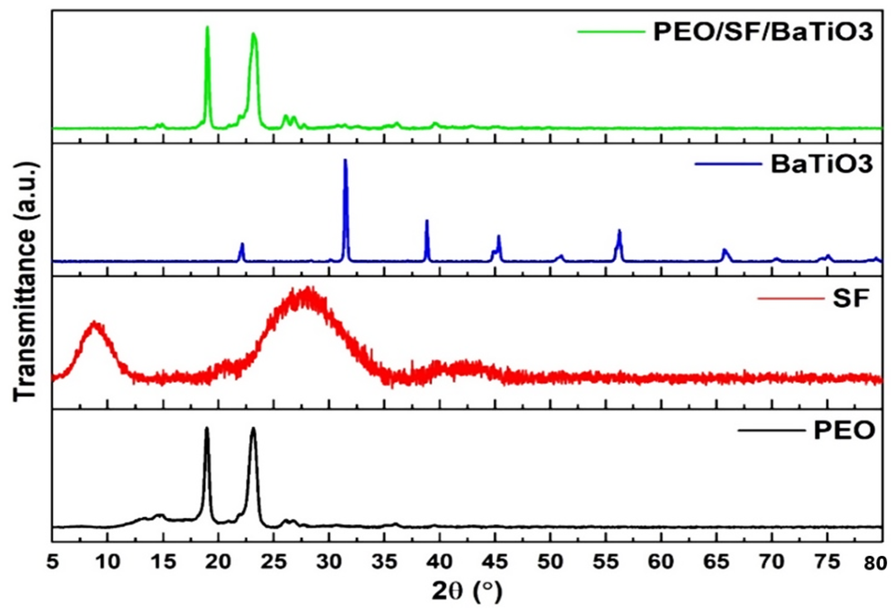
PEO is a semi-crystalline polymer, meaning it has both crystalline and amorphous regions. XRD can help to quantify the amount of crystalline and amorphous material in a sample, which is essential for understanding its physical and mechanical properties. The physical and mechanical properties of PEO polymer materials can be significantly influenced by their crystal structure. Crystalline materials have a regular and repeating arrangement of atoms or molecules, while amorphous materials lack a long-range order in their atomic arrangement. In general, crystalline materials tend to have more well-defined physical and mechanical properties than amorphous materials, which often exhibit more significant variability and a broader range of properties. As shown in Figure 2, the XRD profile of the PEO, SF, and PEO/15 wt% SF/0.2 wt% BaTiO3 composites have been reported. The reported peaks demonstrated that the pure PEO polymer powder has a crystalline structure, represented by the strongly reflected peaks at 19.6° and 23.4. However, SF is a natural polymer found in silk films, and it has a hierarchical structure consisting of both crystalline and amorphous regions. The hierarchical structure of silk fibroin can be described at multiple levels, including at the primary structure (the sequence of amino acids that make up the protein); the secondary structure, which refers to the local spatial arrangement of the protein chains; the tertiary structure, which refers to the overall 3D conformation of the protein molecule; and the quaternary structure, which refers to the organization of multiple protein molecules to form larger structures, such as fibers or films. Overall, the hierarchical structure of silk fibroin is critical to its unique mechanical and physical properties, such as high strength, flexibility, and biocompatibility, which make it a promising material for various biomedical applications. Barium titanate is a perovskite-type oxide with a unique combination of ferroelectric, piezoelectric, and dielectric properties, making it a valuable material in various applications.
As shown in Figure 2’s first profile, the XRD of PEO exhibits a semi-crystalline structure, which contains both ordered and disordered regions. The most prominent peaks in the XRD pattern of PEO are typically observed at 2θ angles of approximately 19°, 23°, and 28°. The peak at 2θ ≈ 19° corresponds to the (110) crystallographic plane of the orthorhombic crystal structure of PEO. The peak at 2θ ≈ 23° corresponds to the (040) plane, while the peak at 2θ ≈ 28° corresponds to the (130) plane.
The second profile in the XRD analysis belongs to SF. Like PEO, SF is known to have a semi-crystalline structure with both ordered and disordered regions. The most prominent peaks are typically observed at 2θ angles of approximately 9° and 28°. The third profile is the X-ray diffraction pattern of barium titanate, which typically consists of several sharp peaks corresponding to the material’s crystalline planes. The peak at around 20–25° 2θ corresponds to the (200) crystal plane. The peak corresponds to the 311 crystal plane, which is typically approximately 30–35° 2θ. The other three peaks correspond to the 222, 400, and 440 crystal planes, located at 35–40, 40–45, and 55–60°, respectively. The fourth profile is for the designed PEO/15 wt% SF/0.2 wt% BaTiO3 composite. As can be seen, the peak of the SF at 28° is covered under the PEO peak. These PEO peaks were also identified, analyzed, and reported by Zhang et al. [33,34]. The featured peaks of BaTiO3 nanomaterials could not be detected due to the low concentration of the piezoelectric material additives. Additionally, the other crystalline peaks attributed to SF could not be observed due to the amorphous structure of the SF as an amorphous molecular aggregate in films.
The FTIR spectroscopy of polyethylene oxide (PEO) typically exhibits several peaks in the mid-infrared region (4000 to 500 cm−1) that can be associated with specific vibrational modes of the polymer, as can be seen in Figure 3 (3000–2500 cm−1). The O-H stretching vibration, characteristic of hydroxyl groups, dominates this region. The region of 1440–1360 cm−1 is due to the asymmetric stretching of the -CH2- groups. The peak appeared at 1240 cm−1, corresponding to the symmetric stretching of the -CH2- groups. At 1040–960 cm−1, the region is dominated by the bending vibrations of the -CH2- groups. It is important to note that the exact position, intensity, and shape of these peaks may vary depending on the degree of crystallinity, molecular weight, and other factors of the analyzed PEO sample.
FTIR spectroscopy of SF typically shows several peaks corresponding to specific functional groups or vibrations in the molecule. The amide I peak is generally observed around 1650 cm−1 due to the C=O stretching vibrations in the amide groups (C=O-N-H) of the SF molecule. The amide II band can be observed around 1550 cm−1 due to the N-H bending vibrations in the amide groups of the SF molecule. The amide III band peak can be observed around 1300 cm−1 due to the C-N stretching vibrations in the amide groups of the SF molecule. The barium titanate could not be detected due to the small sample size; there may not be enough infrared light absorbed to produce a meaningful signal.
TGA analysis is shown in Figure 4a. The measure of the samples’ weight-change as a function of temperature in a controlled atmosphere was reported. All TGA profiles started to degrade at around 200–300 °C and underwent a weight loss of about 10–20%. The TGA trend of PEO provides information about the thermal stability of the material and the chemical reactions that occur as the temperature increases. In the TGA of PEO, we can typically observe a decrease in weight as the temperature increases in the first stage, which is due to the loss of water and residual solvents from the sample. At higher temperatures, we can observe a more rapid weight loss as the polymer begins deleting, caused by depolymerization, chain scission, and crosslinking reactions. The temperature at which the maximum weight loss occurs and the extent of weight loss can be used to estimate the thermal stability of the composite. It is also important to note that the presence of BaTiO3 additives significantly affects the thermal stability of the composite and, therefore, its TGA trend. The DSC of PEO is shown in Figure 4b. It can be seen that PEO exhibits a single, sharp endothermic peak in its DSC curve, which is indicative of its melting behavior. The endothermic peak occurs at the melting temperature of the PEO, typically in the range of 63.04 °C. It is also worth noting that the presence of SF and BaTiO3 slightly influences the DSC trend of PEO.
Raman spectroscopy is a helpful tool for studying a material’s molecular structure and properties and can provide valuable insights into a material’s behavior in various applications. Figure 5 shows the Raman spectroscopy of pristine PEO, PEO/15 wt%SF, and PEO/15 wt% SF/0.2 wt% BaTiO3. The Raman spectrum of PEO typically exhibits a broad and intense band in the region of 1000–1700 cm−1, which is associated with the stretching vibrations of the C-O-C bonds in the polymer backbone. The unique molecular vibrations of SF give rise to a series of characteristic peaks in the Raman spectrum, which can identify the presence of specific chemical bonds and functional groups within the molecule. In the case of SF, the Raman spectrum typically exhibits several firm peaks in the region of 1000 to 1700 cm−1, corresponding to the vibrations of the amide I (C=O stretching) and amide II (C-N stretching) functional groups. These peaks’ precise position, intensity, and shape can be used to distinguish between different SF types and understand the effects of processing and age on the material.
Additionally, the presence of sharp peaks in the spectrum, for example, indicates a high degree of crystallinity, while broad peaks may indicate a more amorphous structure. The intensity ratios of different peaks can also be used to determine the orientation of the SF molecules within the proposed composite. However, adding SF and BaTiO3 significantly alters the Raman spectra of PEO. BaTiO3 is a well-known ferroelectric material with a high dielectric constant and a significant electromechanical coupling coefficient. When BaTiO3 particles are added to PEO, the resulting composite material changes the intensity and position of the Raman peaks. This shift in the Raman peaks is attributed to the interaction between the PEO and BaTiO3. Despite the low amount of BaTiO3, the high dielectric constant of BaTiO3 affects the polarization of the PEO chains, leading to changes in their vibrational modes and, thus, the Raman spectra.

3.2. Piezoelectric Properties Evaluation

Piezoelectric properties are the electrical properties of certain materials that cause them to generate a voltage in response to mechanical stress and to change in shape when subjected to an electric field. The natural cardiac tissue is piezoelectric, which produces an electrical charge in response to mechanical deformation [35]. The mechanical deformation, in this case, is the contraction and stretching of the heart muscle films during the heart’s beating cycle. This piezoelectric effect in the heart can be measured using electrocardiograms (ECGs), providing important information about the heart’s electrical activity and function. Additionally, the piezoelectric properties of the heart tissue are also thought to play a role in generating and propagating electrical impulses in the heart. The human heart generates small electrical signals measured in millivolts (mV). The exact voltage generated by the heart depends on several factors, including the size and structure of the heart, the properties of the heart tissue, and the specific electrical signals being measured. Thus, artificial cardiac tissue must exhibit piezoelectric properties like natural ones [36,37]. Piezoelectric biomaterials have emerged as an increasingly significant field of study. Biopolymers, such as collagen and polyvinylidene fluoride, and combinations with other materials, such as polycaprolactone and MWCNT, are research focal points [38]. Polyvinylidene fluoride (PVDF) has good piezoelectric properties, especially when mixed with BaTiO3-Ag. However, those materials suffer from low biodegradability [39].
On the other hand, SF demonstrated a high apparent piezoelectric coefficient and maintained its good electroactive properties [40]. However, the phase limits the dipole when SF transforms from silk I to silk II. Thus, adding piezoelectric nanoparticles will enhance the output voltage and piezoelectrical characteristics of the newly designed PEO/SF composite.
Figure 6a shows the relationship between the applied load and the output voltage for PEO/SF/BaTiO3. The prepared samples were tested in tapping mode, and all samples were subject to a frequency of 100 Hz and different applied loads ranging from 1 to 20 N. The output voltage increased with increasing applied load. The slope seems to be non-linear, and this is due to fracture or deformation due to high load. However, it is essential to note that the exact correlation between force and voltage may depend on the piezoelectric device’s specific geometry, configuration, and material properties. Several devices have been designed to measure the piezoelectric performance based on the applied force [41]. The devices’ configurations are different and use different applied load modes. The relationship between force and voltage depends on the device used to perform the measurements. However, the relationship of the presented data in Figure 6a is somehow linear. A maximum of around 1100 mV was obtained at a load of 20 N. The corresponding piezoelectric materials generated harmonics noise voltage at different applied forces, and a 100 Hz frequency is shown in Figure 6b. An oscilloscope was used to identify the output signals of piezoelectric materials. The voltage was measured across the material when it was mechanically deformed or vibrated. The output signal had a waveform corresponding to the mechanical input’s frequency and amplitude. Additionally, the output voltage peak increased with increasing the applied force.
Figure 7a shows the relationship between the frequency and the output voltage for PEO/15 wt% SF/0.2 wt%BaTiO3. The prepared samples were tested in tapping mode, and all samples were subjected to the same applied load of 1 N and various frequencies ranging from 10 to 100 Hz, which matched the heartbeats. The output voltage increased when the frequency increased. The slope shows linear behavior. A value of around 80 mV was obtained at 100 Hz frequency, which agrees with the generated electricity by the human heart. The corresponding piezoelectric materials generated harmonics noise voltage at different frequencies, and a constant applied load of 1 N is shown in Figure 7b. The piezoelectric materials’ output signals were identified using an oscilloscope. The voltage was measured across the material when it was mechanically deformed. The output signal has a waveform corresponding to the mechanical input’s frequency and amplitude. Additionally, the output voltage peak increased with increasing frequency.

3.3. PEO/SF/BaTiO3 In Vitro Study: MTT

MTT is a commonly used colorimetric assay in in vitro studies to measure cell viability, proliferation, and cytotoxicity. The MTT assay is a simple and reliable method for assessing cell viability and proliferation in vitro. The MTT assay is based on the ability of viable cells to reduce MTT to formazan crystals, which can be quantified spectrophotometrically. Before starting the test, the cells were seeded in a 96-well plate with 10,000 cell/well density and allowed to grow for a specified period. At the end of the incubation period, MTT solution was added to the wells, and the plate was returned to the incubator for different periods. The MTT was then reduced by metabolically active cells to formazan crystals, which were solubilized with a detergent solution. The formazan produced was proportional to the number of viable cells in the well and could be quantified using a spectrophotometer. Spectrophotometers are potent tools for measuring the properties of light and can provide valuable information about the composition and structure of materials in many scientific fields.
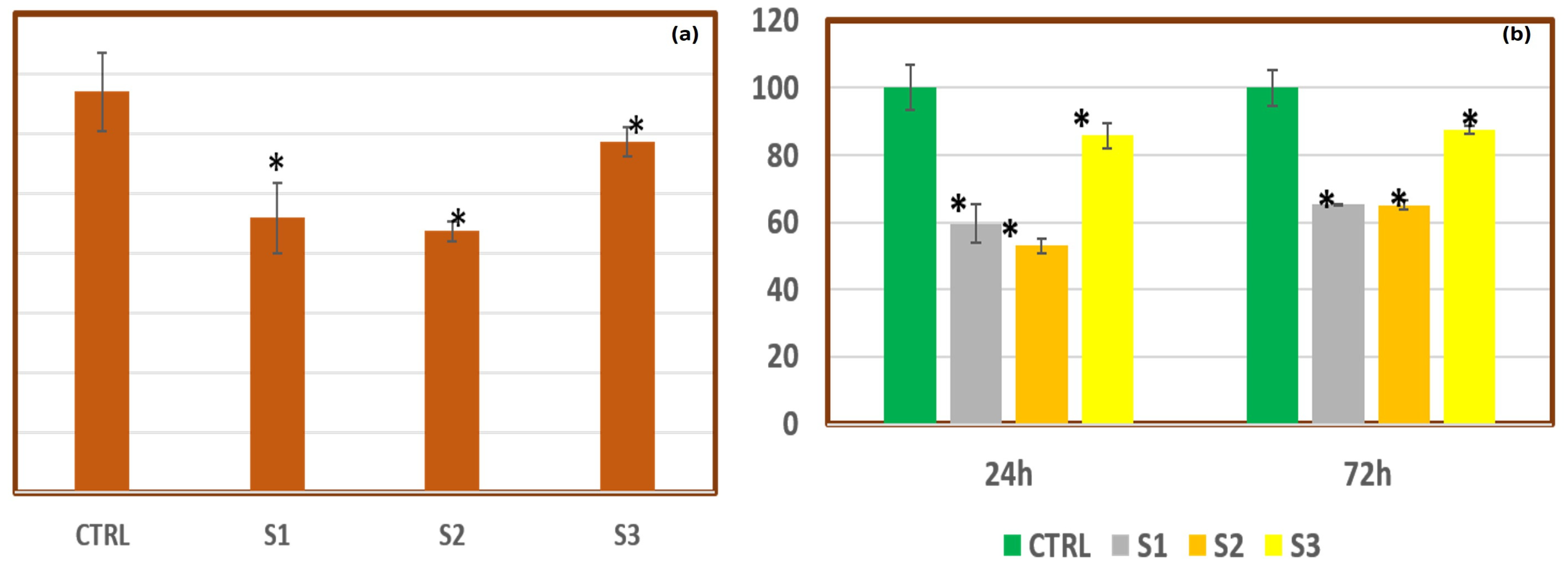
Figure 8 shows the in vitro study MTT of PEO/15 wt%SF/0.2 wt%BaTiO3 blends, (a) AC16 cells’ viability, and (b) cytotoxicity effect against AC16 cells. AC16 cells are a cardiac cell line derived from human ventricular tissue. ANOVA software was used as the statistical analysis tool, in which data significance was accepted when p < 0.05, and all data were represented as mean ± SD. A control sample was used as a baseline reference for comparison with the experimental group, as seen in Figure 8a. The purpose of the control sample is to provide a standard against which to measure the effects of the experimental treatment and to ensure that any observed changes are due to the treatment being tested and not to other factors. As seen in Figure 8, the pristine PEO cell viability either was not affected by adding SF or slightly decreased. It is well known that SF is a biocompatible and supportive material for cell growth and viability. However, the cell viability of SF can vary depending on various factors, such as the concentration, the type of cells used, and the culture conditions. Noticeably, the cell viability dramatically increased, almost as much as the control sample, when adding BaTiO3 to the PEO/SF composites. Adding BaTiO3 to PEO/SF improves cell adhesion and proliferation, especially for AC16 and other cardiac-related cells. This may be due to the piezoelectric properties of BaTiO3, which can stimulate cell growth and activity, particularly at low concentrations.
Confocal microscopy is a powerful imaging technique to study biological specimens in vitro. Confocal microscopy allows us to observe tissues in three high-resolution dimensions, providing detailed information about the structure, function, and behavior. Confocal microscopy is particularly useful for studying the distribution of specific molecules or structures within cells or tissues. Labeling these molecules with fluorescent probes allows researchers to visualize their location and movement within the specimen.
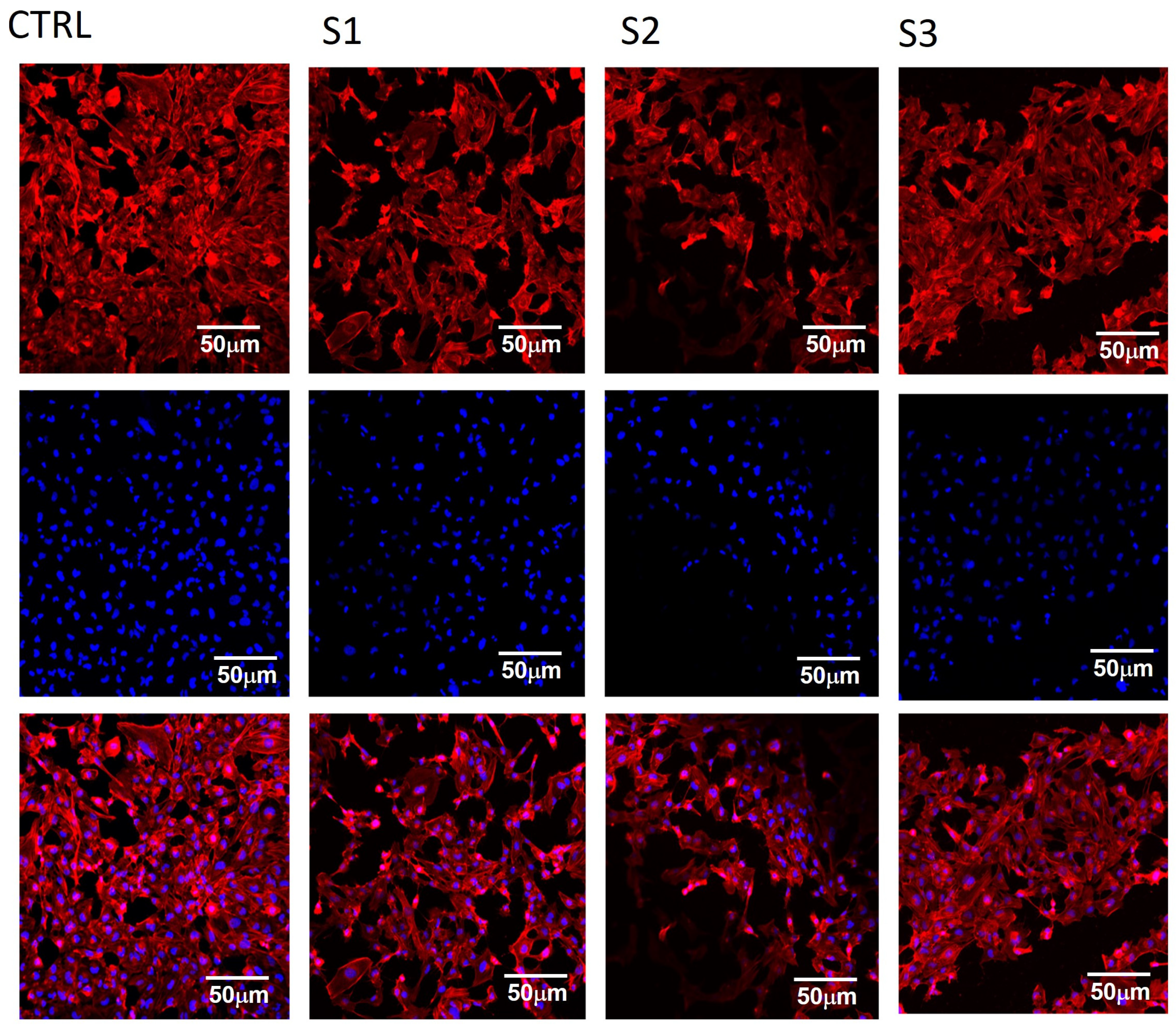
Figure 9 shows images taken using confocal microscopy of PEO/SF%BaTiO3 specimens. The effect of blends on AC16 cell morphology was reported. CTRL is the control sample, S1 is the pristine PEO, S2 is PEO/SF, and S2 is the PEO/SF/BaTiO3. As can be seen, the collection of high-resolution images of fluorescently labeled specimens indicated that the adhesion was further confirmed by confocal imaging (Figure 9). It was observed that the cells showed a spread morphology on all samples. The cells adhered to the PEO membranes and demonstrated a well-spread morphology and spindle shape, like the positive control seeded on the glass coverslips. Filamentous actin film organization was somehow more evident on the S2 and S3 membranes compared to the bare PEO membrane. The cells on the PEO membranes showed a relatively round morphology, which could be attributed to the bio-inert nature of the PEO membranes. However, to some extent, we can observe the cytotoxic effects of BaTiO3, mainly when the particles are not adequately dispersed in the polymer matrix. Overall, the impact of adding BaTiO3 on the cell viability of PEO is complex and depends on many factors before using this composite material for biomedical applications.

4. Conclusions

We successfully developed a three-dimensional composite heart patch that exhibits electrical conductivity, allowing it to simulate the integrated electrical functions of heart muscle cells. The piezoelectric characteristics of the PEO/SF were induced by incorporating BaTiO3 magnetic nanoparticles through a simple and cost-effective preparation method. A PiezoTester device was used to evaluate the piezoelectric properties of the prepared PEO/15 wt% SF/0.2 wt% BaTiO3 composite heart patch. The cytotoxicity effect of the prepared composite patch was tested against AC16 cells using an MTT assay at a load of 20 N. A maximum voltage of approximately 1100 mV was obtained. Remarkably, the composite material achieved a maximum output of around 80 mV at a frequency of 100 Hz, matching the typical electrical production of the human heart and demonstrating its potential to mimic the electrical behavior of cardiac tissue effectively. Moreover, adding BaTiO3 to the PEO/SF composites significantly enhanced cell viability. This finding was confirmed through confocal microscope images, which showed that the cells exhibited a uniformly spread morphology, firmly adhering to the PEO membranes and demonstrating excellent biocompatibility.

Author Contributions

Conceptualization, A.K.A.K. and A.A.-h.; methodology, K.A.K. and H.F.; formal analysis, A.K.A.K.; investigation, K.A.K. and N.M.A.E.-s.; resources, H.F.; data curation, A.K.A.K.; writing—original draft preparation, K.A.K. and A.K.A.K.; writing—review and editing, H.F. and K.A.K.; visualization, A.K.A.K.; funding acquisition, H.F. All authors have read and agreed to the published version of the manuscript.

Funding

This project was funded by the National Plan for Science, Technology, and Innovation (MAARIFAH), King Abdulaziz City for Science and Technology, Kingdom of Saudi Arabia, Award Number (15-BIO4042-02).

Data Availability Statement

The data that support the findings of this study are available from the corresponding author upon request.

Conflicts of Interest

The authors declare no conflict of interest that may be perceived as inappropriately influencing the representation or interpretation of reported research results.

References

  1. Taylor, D.O.; Edwards, L.B.; Aurora, P.; Christie, J.D.; Dobbels, F.; Kirk, R.; Rahmel, A.O.; Kucheryavaya, A.Y.; Hertz, M.I. Registry of the International Society for Heart and Lung Transplantation: Twenty-fifth official adult heart transplant report. J. Heart Lung Transplant. 2008, 27, 943–956. [Google Scholar] [CrossRef] [PubMed]
  2. Bardy, G.H.; Lee, K.L.; Mark, D.B.; Poole, J.E.; Packer, D.L.; Boineau, R.; Domanski, M.; Troutman, C.; Anderson, J.; Johnson, G. Amiodarone or an implantable cardioverter-defibrillator for congestive heart failure. N. Engl. J. Med. 2005, 352, 225–237. [Google Scholar] [CrossRef] [PubMed]
  3. Langone, A.J.; Helderman, J.H. Disparity between Solid-Organ Supply and Demand. N. Engl. J. Med. 2003, 349, 704. [Google Scholar] [CrossRef] [PubMed]
  4. Granger, C.B.; McMurray, J.J.; Yusuf, S.; Held, P.; Michelson, E.L.; Olofsson, B.; Östergren, J.; Pfeffer, M.A.; Swedberg, K. Effects of candesartan in patients with chronic heart failure and reduced left-ventricular systolic function taking angiotensin-converting-enzyme inhibitors: The CHARM-Added trial. Lancet 2003, 362, 772–776. [Google Scholar] [CrossRef] [PubMed]
  5. Pitt, B.; Zannad, F.; Remme, W.J.; Cody, R.; Castaigne, A.; Perez, A.; Palensky, J.; Wittes, J. The effect of spironolactone on morbidity and mortality in patients with severe heart failure. Randomized Aldactone Evaluation Study Investigators. N. Engl. J. Med. 1999, 341, 709–717. [Google Scholar] [CrossRef]
  6. Picascia, A.; Grimaldi, V.; Zullo, A.; Infante, T.; Maiello, C.; Crudele, V.; Sessa, M.; Mancini, F.P.; Napoli, C. Experimental and clinical transplantation: Official journal of the Middle East Society for Organ Transplantation. MESOT 2012, 10, 209. [Google Scholar]
  7. Brautbar, A.; Ballantyne, C.M. Pharmacological strategies for lowering LDL cholesterol: Statins and beyond. Nat. Rev. Cardiol. 2011, 8, 253–265. [Google Scholar] [CrossRef]
  8. Brizzio, M.E.; Zapolanski, A. Reviews in cardiovascular medicine. RCM 2011, 12, S40. [Google Scholar]
  9. Nolan, C.J.; Damm, P.; Prentki, M. Type 2 diabetes across generations: From pathophysiology to prevention and management. Lancet 2011, 378, 169–181. [Google Scholar] [CrossRef]
  10. Zhao, D.; Qi, Y.; Zheng, Z.; Wang, Y.; Zhang, X.-Y.; Li, H.-J.; Liu, H.-H.; Zhang, X.-T.; Du, J.; Liu, J. Dietary factors associated with hypertension. Nat. Rev. Cardiol. 2011, 8, 456–465. [Google Scholar] [CrossRef]
  11. Trialists, F.T. Indications for fibrinolytic therapy in suspected acute myocardial infarction: Collaborative overview of early mortality and major morbidity results from all randomised trials of more than 1000 patients. Lancet 1994, 343, 311–322. [Google Scholar]
  12. Antman, E.M.; Morrow, D.A.; McCabe, C.H.; Murphy, S.A.; Ruda, M.; Sadowski, Z.; Budaj, A.; López-Sendón, J.L.; Guneri, S.; Jiang, F. Enoxaparin versus Unfractionated Heparin with Fibrinolysis for ST-Elevation Myocardial Infarction. N. Engl. J. Med. 2006, 354, 1477–1488. [Google Scholar] [CrossRef] [PubMed]
  13. Schömig, A.; Kastrati, A.; Dirschinger, J.; Mehilli, J.; Schricke, U.; Pache, J.; Martinoff, S.; Neumann, F.-J.; Schwaiger, M. Coronary Stenting plus Platelet Glycoprotein IIb/IIIa Blockade Compared with Tissue Plasminogen Activator in Acute Myocardial Infarction. N. Engl. J. Med. 2000, 343, 385–391. [Google Scholar] [CrossRef] [PubMed]
  14. Kannel, M.W.B. Incidence and epidemiology of heart failure. Heart Fail. Rev. 2000, 5, 167–173. [Google Scholar] [CrossRef] [PubMed]
  15. Swedberg, K.; Kjekshus, J. Effects of enalapril on mortality in severe congestive heart failure: Results of the Cooperative North Scandinavian Enalapril Survival Study (CONSENSUS). Am. J. Cardiol. 1988, 62, 60A–66A. [Google Scholar] [CrossRef]
  16. Abdal-hay, A.; Pant, H.R.; Lim, J.K. Super-hydrophilic electrospun nylon-6/hydroxyapatite membrane for bone tissue engineering. Eur. Polym. J. 2013, 49, 1314–1321. [Google Scholar] [CrossRef]
  17. Badrossamay, M.R.; McIlwee, H.A.; Goss, J.A.; Parker, K.K. Nanofiber Assembly by Rotary Jet-Spinning. Nano Lett. 2010, 10, 2257–2261. [Google Scholar] [CrossRef]
  18. Chien, K.R. Stress pathways and heart failure. Cell 1999, 98, 555–558. [Google Scholar] [CrossRef]
  19. Epstein, F.H.; Hunter, J.J.; Chien, K.R. Signaling pathways for cardiac hypertrophy and failure. N. Engl. J. Med. 1999, 341, 1276–1283. [Google Scholar]
  20. Van der Linde, D.; Konings, E.E.; Slager, M.A.; Witsenburg, M.; Helbing, W.A.; Takkenberg, J.J.; Roos-Hesselink, J.W. Birth prevalence of congenital heart disease worldwide: A systematic review and meta-analysis. J. Am. Coll. Cardiol. 2011, 58, 2241–2247. [Google Scholar] [CrossRef]
  21. Akins, R.E., Jr.; Rockwood, D.; Robinson, K.G.; Sandusky, D.; Rabolt, J.; Pizarro, C. Three-dimensional culture alters primary cardiac cell phenotype. Tissue Eng. Part A 2009, 16, 629–641. [Google Scholar] [CrossRef] [PubMed]
  22. Battista, S.; Guarnieri, D.; Borselli, C.; Zeppetelli, S.; Borzacchiello, A.; Mayol, L.; Gerbasio, D.; Keene, D.R.; Ambrosio, L.; Netti, P.A. The effect of matrix composition of 3D constructs on embryonic stem cell differentiation. Biomaterials 2005, 26, 6194–6207. [Google Scholar] [CrossRef] [PubMed]
  23. Fomovsky, G.M.; Thomopoulos, S.; Holmes, J.W. Contribution of extracellular matrix to the mechanical properties of the heart. J. Mol. Cell. Cardiol. 2010, 48, 490–496. [Google Scholar] [CrossRef] [PubMed]
  24. Reilly, G.C.; Engler, A.J. Intrinsic extracellular matrix properties regulate stem cell differentiation. J. Biomech. 2010, 43, 55–62. [Google Scholar] [CrossRef] [PubMed]
  25. Gomez-Florit, M.; Pardo, A.; Domingues, R.M.A.; Graça, A.L.; Babo, P.S.; Reis, R.L.; Gomes, M.E. Natural-Based Hydrogels for Tissue Engineering Applications. Molecules 2020, 25, 5858. [Google Scholar] [CrossRef]
  26. Pardo, A.; Gómez-Florit, M.; Barbosa, S.; Taboada, P.; Domingues, R.M.; Gomes, M.E. Magnetic Nanocomposite Hydrogels for Tissue Engineering: Design Concepts and Remote Actuation Strategies to Control Cell Fate. ACS Nano 2021, 15, 175–209. [Google Scholar] [CrossRef]
  27. Pardo, A.; Bakht, S.M.; Gomez-Florit, M.; Rial, R.; Monteiro, R.F.; Teixeira, S.P.; Taboada, P.; Reis, R.L.; Domingues, R.M.A.; Gomes, M.E. Magnetically-Assisted 3D Bioprinting of Anisotropic Tissue-Mimetic Constructs. Adv. Funct. Mater. 2022, 32, 2208940. [Google Scholar] [CrossRef]
  28. Altman, G.H.; Diaz, F.; Jakuba, C.; Calabro, T.; Horan, R.L.; Chen, J.; Lu, H.; Richmond, J.; Kaplan, D.L. Silk-based biomaterials. Biomaterials 2003, 24, 401–416. [Google Scholar] [CrossRef]
  29. Gotoh, Y.; Tsukada, M.; Minoura, N. Effect of the chemical modification of the arginyl residue in Bombyx mori silk fibroin on the attachment and growth of fibroblast cells. J. Biomed. Mater. Res. 1998, 39, 351–357. [Google Scholar] [CrossRef]
  30. Gotoh, Y.; Tsukada, M.; Minoura, N.; Imai, Y. Synthesis of poly(ethylene glycol)-silk fibroin conjugates and surface interaction between L-929 cells and the conjugates. Biomaterials 1997, 18, 267–271. [Google Scholar] [CrossRef]
  31. Cai, K.; Yao, K.; Cui, Y.; Yang, Z.; Li, X.; Xie, H.; Qing, T.; Gao, L. Influence of Different Surface Modification Treatments on Poly (D, L-lactic acid) with Silk Fibroin and their Effects on the Culture of Osteoblast in vitro. Biomaterials 2002, 23, 1603–1611. [Google Scholar] [CrossRef] [PubMed]
  32. Fouad, H.; Khalil, K.A.; Alshammari, B.A.; Abdal-hay, A.; Abd El-salam, N.M. Development of New Bio-Composite of PEO/Silk Fibroin Blends Loaded with Piezoelectric Material. Polymers 2022, 14, 4209. [Google Scholar] [CrossRef] [PubMed]
  33. Zhang, J.F.; Yang, D.Z.; Xu, F.; Zhang, Z.P.; Yin, R.X.; Nie, J. Electrospun core-shell structure nanofibers from a homogeneous solution of poly(ethylene oxide)/chitosan. Macromolecules 2009, 42, 5278–5528. [Google Scholar] [CrossRef]
  34. Frenot, A.; Chronakis, I.S. Polymer nanofibers assembled by electrospinning. Curr. Opin. Colloid Interface Sci. 2003, 8, 64–75. [Google Scholar] [CrossRef]
  35. Chirakanphaisarn, N.; Thongkanluang, T.; Chiwpreechar, Y. Heart rate measurement and electrical pulse signal analysis for subjects span of 20–80 years. J. Electr. Syst. Inf. Technol. 2018, 5, 112–120. [Google Scholar] [CrossRef]
  36. Thiene, G.; Basso, C.; Cozza, A.; Zanatta, A. The fascinating discovery of the electrical system in the heart: A story telling. Int. J. Cardiol. 2020, 317, 81–85. [Google Scholar] [CrossRef]
  37. Chen, S.; Hsieh, M.H.; Li, S.H.; Wu, J.; Weisel, R.D.; Chang, Y.; Sung, H.W.; Li, R.K. A conductive cell-delivery construct as a bioengineered patch that can improve electrical propagation and synchronize cardiomyocyte contraction for heart repair. J. Control. Release 2020, 320, 73–82. [Google Scholar] [CrossRef]
  38. Gibbs, A.; McNamee, E.; Slade, D. Piezoelectric nanofibers as biomaterials for bone regeneration and wound healing. In Undergraduate Research in MSE; Review Article; University of Washington URSME: Seattle, WA, USA, 2020; Volume 1, Available online: https://digital.lib.washington.edu/researchworks/handle/1773/46255 (accessed on 15 March 2023).
  39. Dashtizad, S.; Alizadeh, P.; Yourdkhani, A. Improving piezoelectric properties of PVDF fibers by compositing with BaTiO3-Ag particles prepared by sol-gel method and photochemical reaction. J. Alloys Compd. 2021, 883, 160810. [Google Scholar] [CrossRef]
  40. Sencadas, V.; Garvey, C.; Mudie, S.; Kirkensgaard, J.J.; Gouadec, G.; Hauser, S. Electroactive properties of electrospun silk fibroin for energy harvesting applications. Nano Energy 2019, 66, 104106. [Google Scholar] [CrossRef]
  41. Sorayani Bafqi, M.S.; Sadeghi, A.H.; Latifi, M.; Bagherzadeh, R. Design and fabrication of a piezoelectric output evaluation system for sensitivity measurements of fibrous sensors and actuators. J. Ind. Text. 2021, 50, 1643–1659. [Google Scholar] [CrossRef]
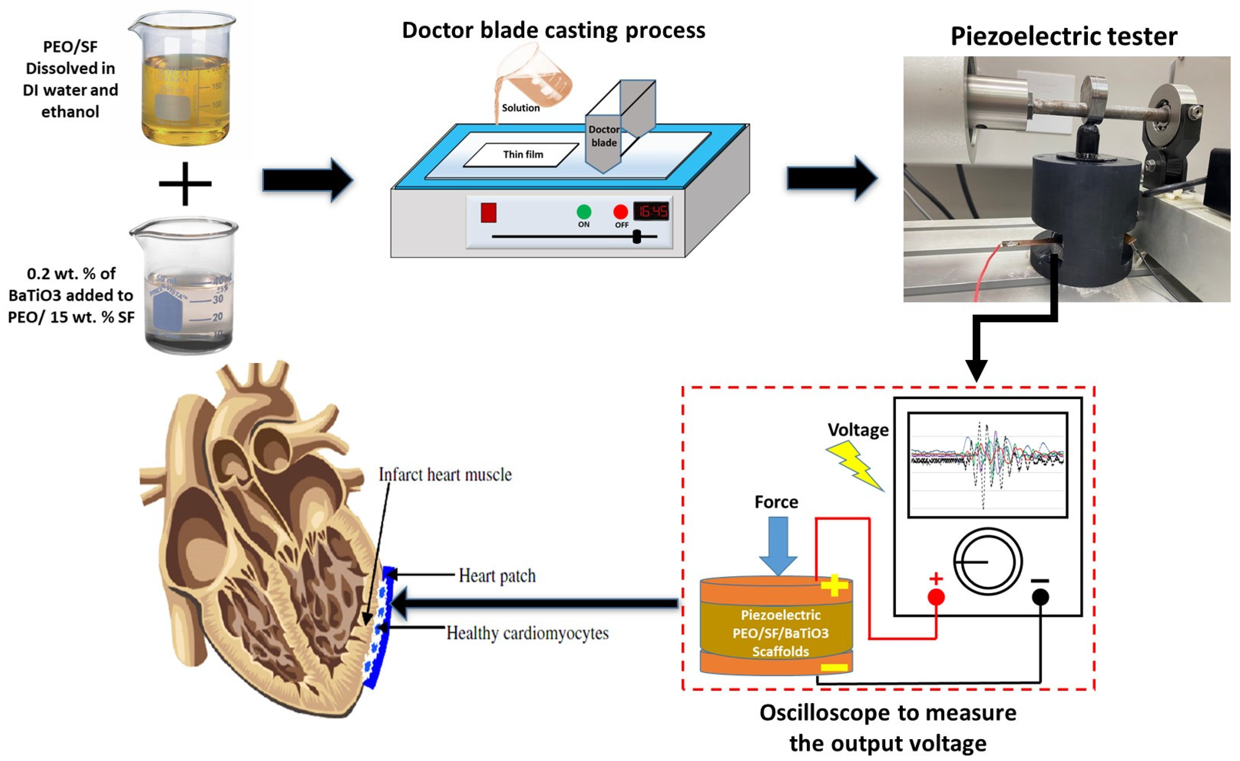
Figure 1. A schematic diagram of the thin-film processing and the cam-connected hammer used to test the piezoelectric properties.
Jcs 07 00200 g001
Figure 2. XRD of pristine PEO, PEO/15 wt% SF, and PEO/15 wt% SF/0.2 wt% BaTiO3.
Jcs 07 00200 g002
Figure 3. FTIR of pristine PEO, PEO/15 wt% SF, and PEO/15 wt% SF/0.2 wt% BaTiO3.
Jcs 07 00200 g003
Figure 4. (a) TGA and (b) DSC thermal analysis of fabricated pure and composite films.
Jcs 07 00200 g004
Figure 5. Raman spectroscopy of pristine PEO, PEO/15 wt% SF, and PEO/15 wt% SF/0.2 wt% BaTiO3.
Jcs 07 00200 g005
Figure 6. (a) Correlation between the force and the output voltage for PEO, PEO/15 wt% SF, and PEO/15 wt% SF/0.2 wt%BaTiO3 at a constant frequency of 100 Hz. (b) The piezoelectric materials generated harmonics noise voltage at different applied forces and 100 Hz frequency.
Jcs 07 00200 g006
Figure 7. (a) Correlation between the frequency and the output voltage for PEO/15 wt% SF/0.2 wt% BaTiO3 at a constant applied load of 1 N. (b) Samples of the generated harmonics noise voltage produced by the piezoelectric materials at a different frequency and 1 N applied force.
Jcs 07 00200 g007
Figure 8. In vitro study MTT of PEO/15 wt% SF/0.2 wt% BaTiO3 blends. (a) AC16 cells’ viability. (b) Cytotoxicity effect against AC16 cells. CTRL is the control sample, S1 is the pristine PEO, S2 is PEO/SF, and S3 is the PEO/SF/BaTiO3.
Jcs 07 00200 g008
Figure 9. Confocal microscopic study of the PEO/15 wt% SF/0.2 wt% BaTiO3 blends; effect on AC16 cell morphology; CTRL is the control sample (first column), S1 is the pristine PEO (second column), S2 is PEO/SF (third column), and S2 is the PEO/SF/BaTiO3 (fourth column). The first row represents the signal from actin (red), the second row represents the nuclear DAPI staining (blue), and the third row represents the merged signals.
Jcs 07 00200 g009
Disclaimer/Publisher’s Note: The statements, opinions and data contained in all publications are solely those of the individual author(s) and contributor(s) and not of MDPI and/or the editor(s). MDPI and/or the editor(s) disclaim responsibility for any injury to people or property resulting from any ideas, methods, instructions or products referred to in the content.