Article

Meso-Scale Finite Element Model for Rib-Stiffened Composites with Biaxial Weft-Knitted Reinforcements

Institute of Textile Machinery and High Performance Material Technology (ITM), Technische Universität Dresden, 01062 Dresden, Germany
*
Author to whom correspondence should be addressed.
J. Compos. Sci. 2023, 7(5), 175; https://doi.org/10.3390/jcs7050175
Submission received: 30 March 2023 / Revised: 6 April 2023 / Accepted: 14 April 2023 / Published: 24 April 2023
(This article belongs to the Section Composites Modelling and Characterization)

Abstract

:
Shell-rib structures made of textile-reinforced composites are used in a wide range of applications to increase bending, buckling and torsional stiffness. Such composites are usually manufactured in differential construction at the preform level by assembling several textile structures or at the component level by the subsequent joining of separately manufactured shells and stiffening structures. Integral preform production is one way to overcome the disadvantages of the forenamed methods, such as high manual effort, failure during assembling or fiber distortion. Weft-knitting technology is excellent for achieving integral preforms for shell-rib components with a strong connection between the shell and the rib, especially while producing biaxial weft-knitted fabrics (BWKF) with reinforcing yarns in the warp and weft direction to improve its mechanical behavior. In this work, the possibilities of the knitting technique are investigated, and a finite element model for comparing different variants is developed and validated. A meso-scale Finite-Element-Method (FEM) model of the BWKF is used. The simulation results with the meso-scale model show a good correlation with experimental data by a description of bending strength and stiffness of different FRP configuration variations. The model can be used in further investigation of fiber-reinforced polymer (FRP) made from BWKF.

1. Introduction

1.1. Motivation

Ribs, frames or stringers are used in a wide range of applications to increase the bending, buckling and torsional stiffness of highly loaded shell-shaped fiber-reinforced polymer (FRP) components. Typical examples are shell-rib structures in aircraft fuselages, automobiles or ships. According to the state-of-the-art, these components are usually manufactured in differential construction at the preform level by assembling the preform from different textile structures (e.g., by stitching or sewing) or at the component level by the subsequent joining of the separately manufactured shell and the stiffening structure (e.g., by adhesive bonding). Therefore, the production of such FRP components is currently very cost-intensive and, outside the aircraft industry, only suitable for small series or niche applications [1]. The use of fiber placement techniques for complex 3D rib-stiffened FRP is limited [2]. A continuous fiber reinforcement between the shell and stiffeners is, due to process restrictions, almost impossible. The lightweight construction potential of high-performance fibers is, therefore, not fully exploited. Depending on load cases and requirements for stiffness and strength, the dimension and shape of the 3D rib-stiffened FRP can be adapted accordingly. Among many factors, the orientation and height of the ribs play an important role. Figure 1 shows some typical variations of 3D rib-stiffened FRP with different orientations of rib.
Weft-knitting technology offers the possibility of inserting reinforcing yarns in the warp and weft direction of the knitted fabric to improve its mechanical behavior. This results in a high-potential composite reinforcement referred to as biaxial weft-knitted fabric (BWKF) [3]. The possibility of manufacturing integral multilayer BWKF has a high potential for the reinforcement of shell-rib components, as shown in Figure 1. Yarns can be guided in a way that strongly connects the shell and rib. This work investigates the possibilities of the knitting technique and enables comparing of different variants through the development and validation of a finite element model.

1.2. Production Technique for Biaxial Weft-Knitted Fabrics

Hasani et al. [3] give an overview of the use of BWKF as FRP reinforcements. The production of BWKF is carried out on a modified flatbed weft-knitting machine, where a yarn guide and yarn feeder are added for the integration of warp and weft reinforcing yarns [4]. Figure 2 shows the construction of the knitting zone for asymmetric 2- and 4-layer knitted fabrics. Based on the working principle of the BWKF production technique, further knitting techniques for the direct forming of 3D preforms were developed. Three-dimensional spacer BWKF preforms with warp and weft reinforcement on each side and with the fully-fashioned technique in combination with needle parking technique were developed [5]. Tubular fabrics with constant or variable cross-sections and net-shape 3D skin-stringer BWKF with constant or variable height were produced [6]. Knitting machine producer Shima Seiki Mfg., Ltd. (Wakayama, Japan) introduced the first commercial weft-knitting machine with biaxial yarn insertion at JEC World 2022 (Paris, France) and Techtextil Exhibition 2022 (Frankfurt, Germany).
Bollengier et al. [6,7] introduced a one-step manufacturing technique for BWKF preforms for 3D rib-stiffened FRP. This integral BWKF is produced as flat fabric on a knitting machine with a reserve layer of warp yarns (cf. Figure 3). This warp yarn reserve is pulled out and thus transforms the 2D fabric into the 3D integral preform. The possible orientation of the ribs is 0° or 90° (variants 1 and 2 in Figure 1). This manufacturing technique has been further developed for more complex rib orientations, such as variant 3 to variant 7 (Figure 1). Details of this advanced technique are part of future research papers.

1.3. Modeling of Textiles and Textile-Reinforced Composites

Since composite materials exhibit a multi-scale nature, finite element method (FEM) models of composite materials are available on various scales: macro-, meso-, and micro-scale. The macro-scale models are based on continuum mechanics, where the composite laminate is considered a homogenous matter, despite its constitutional structure and its being normally implemented with shell or solid elements. As FRP are anisotropic materials, modeling their mechanical behavior on the macro-scale [8,9] requires suitable composite laminate theories [10] as well as failure criteria [11]. Interface elements can be introduced into models for the description of delamination [12]. The failure criteria for a homogenous structure must be based on the combination of different stress states that occur. Different failure theories have been developed in order to reduce the deviation of their prediction from the test data [11].
Modeling of textile-reinforced composites with high grade of description has been done for various textile reinforcements: woven fabrics [13,14,15,16,17,18,19,20,21,22], braided structure [23,24,25,26,27,28,29,30,31,32,33,34,35], non-crimp fabrics (NCF) [36,37,38,39,40,41,42,43] and weft-knitted fabrics [44,45,46,47].
Meso-scale models are a step forward, as fibers and matrix are modeled separately, and fibers are modeled at the yarn level [13,24,39,44]. This type of model requires more computational effort than macro-scale models but provides the chance to define independent failure criteria for fiber and matrix. Additionally, the configuration of fibers in the structure can be taken into account.
In micro-scale models, yarns are modeled on the filament level (e.g., a bundle of beam elements). Micro-scale models have not yet been widely researched for structural analysis due to their exceptionally high computational cost. Their applications are often limited to a small unit cell to predict the mechanical behavior of FRP when properties of fibers, matrix and fiber-matrix interface are known [48]. Micro-scale models of woven composites can be found in [49,50].
Multi-scale models can also be combined into a one-single computing process, such as the approach of the FE2 method [51]. The multi-scale approach helps to understand the coupling of material behavior and characteristics in a bottom-up design manner, which is important to the optimization of composite structures and their mechanical performance. However, the multi-scale approach requires building up models for certain reinforcing structures at different scales and sufficient test data to validate them. Thus, a multi-scale approach is not used in the scope of this paper.
Authors have previously developed models for conventional knitted fabrics and BWKF on different scales, e.g., [52,53,54,55,56,57,58,59]. In the current paper, a meso-scale model for 3D rib-stiffened FRP made of BWKF reinforcement is introduced to predict structural, mechanical behavior and failure modes. The FRP model is based on previous research [58], where the textile reinforcement was described on a meso-scale with shell elements for the reinforcing yarns and beam elements for the stitch yarns (Figure 4). Both shell and beam elements used linear elastic material models. Single surface contact, including treatment of beam-to-beam contact, was used for the contact between shell and beam elements. The material parameters of shell and beam elements were validated based on tensile test data of glass fiber yarns. The unit cell was generated with an artificial thermo-shrinking process of the beam elements described hereafter. First, a model with loose beam elements as stitch yarns and straight shell elements as reinforcing yarns is built. An artificial thermo shrinking factor is applied in the beam element material. The whole model is exposed to an increased temperature, and only the beam elements gradually reduce their length in every time step. During this process, beam elements start to interact with the shell elements and cause the ondulation of the shell elements. The shorter the beam length, the stronger the interaction between the beam and shell elements, and the higher the grade of ondulation of shell elements. This ondulation is chosen such that it correctly describes the non-linearity of the BWKF during tensile tests. This model was further used in forming simulations of the flat textile into the 3D preform [58].
In this paper, stacked and integral BWKF for T-shaped FRP components are compared experimentally and numerically. Therefore, the BWKF meso-scale model is extended to an FRP model, including typical failure modes, which is a novel approach for modeling BWKF-reinforced composites.

2. Materials and Methods

2.1. Materials

Reinforcing yarns are glass fibers (GF) with a fineness of 1200 tex from P-D Glasseiden GmbH Oschatz (Oschatz, Germany) with the commercial name DR199 EC17-1200-350. Fold yarn GF 2 × 68 tex is used as stitch yarn, which has the commercial name EC-9 68 X 2 S150 1383 and is provided by Culimeta GmbH & Co. KG (Bersenbrück, Germany). For composites consolidation, a mixture of RIMR 135 epoxy resin and RIMH 137 hardener of Hexion Specialty Chemicals (Stuttgart, Germany) is used as the reaction resin. Table 1 provides the material properties of the unreinforced epoxy matrix as given by the producer.

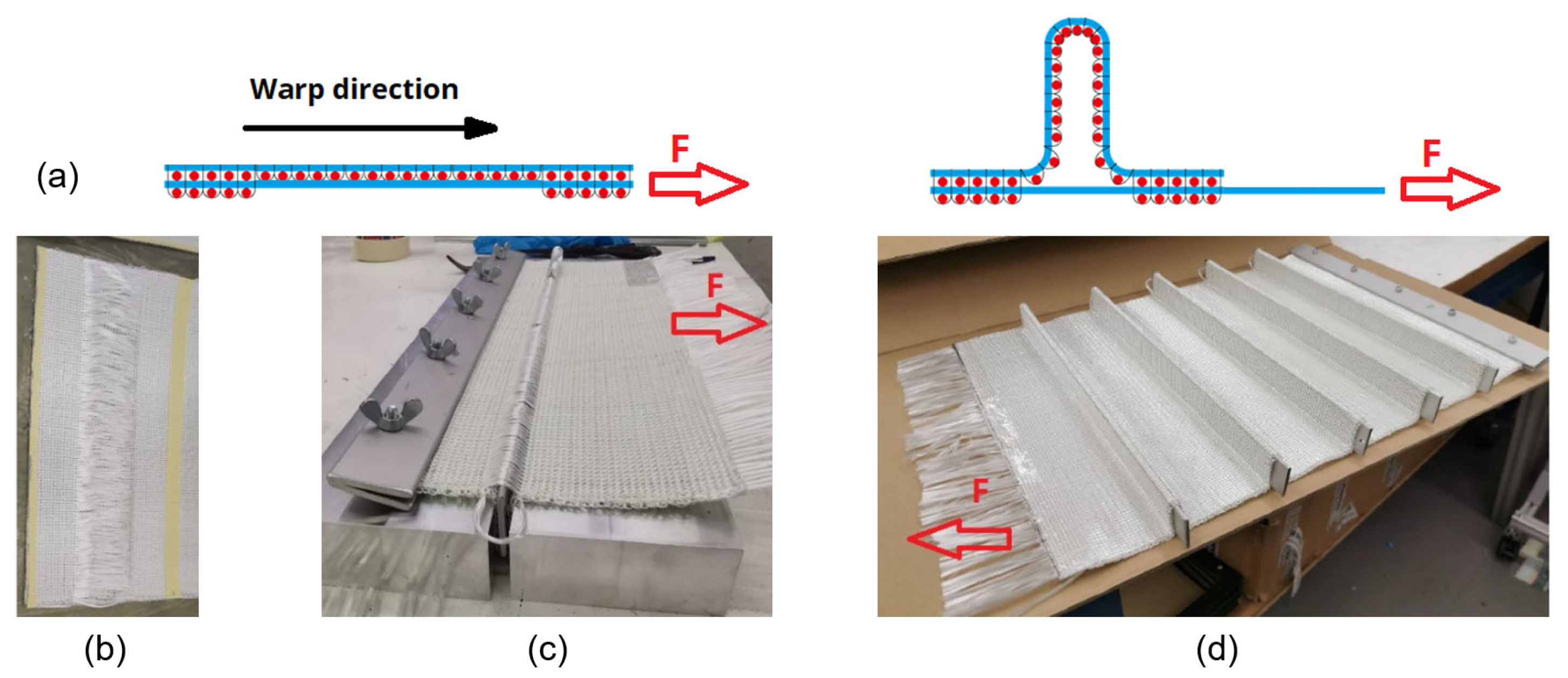
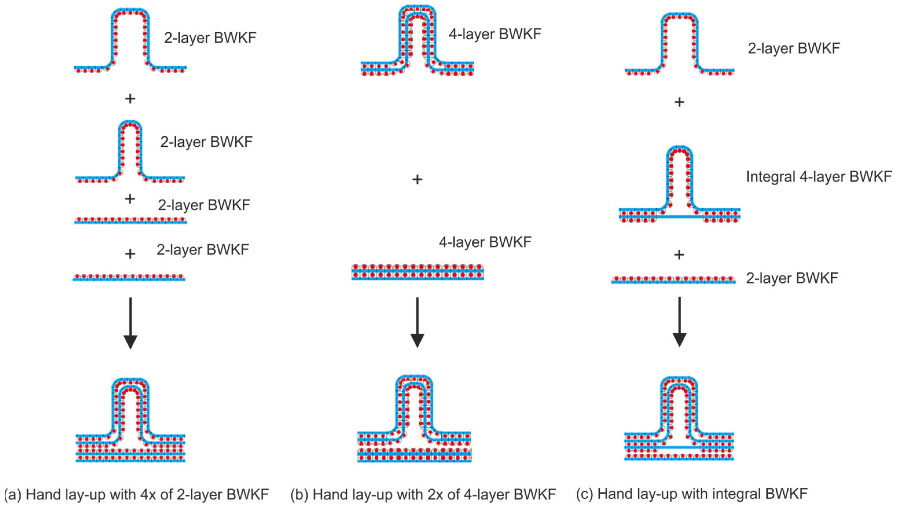
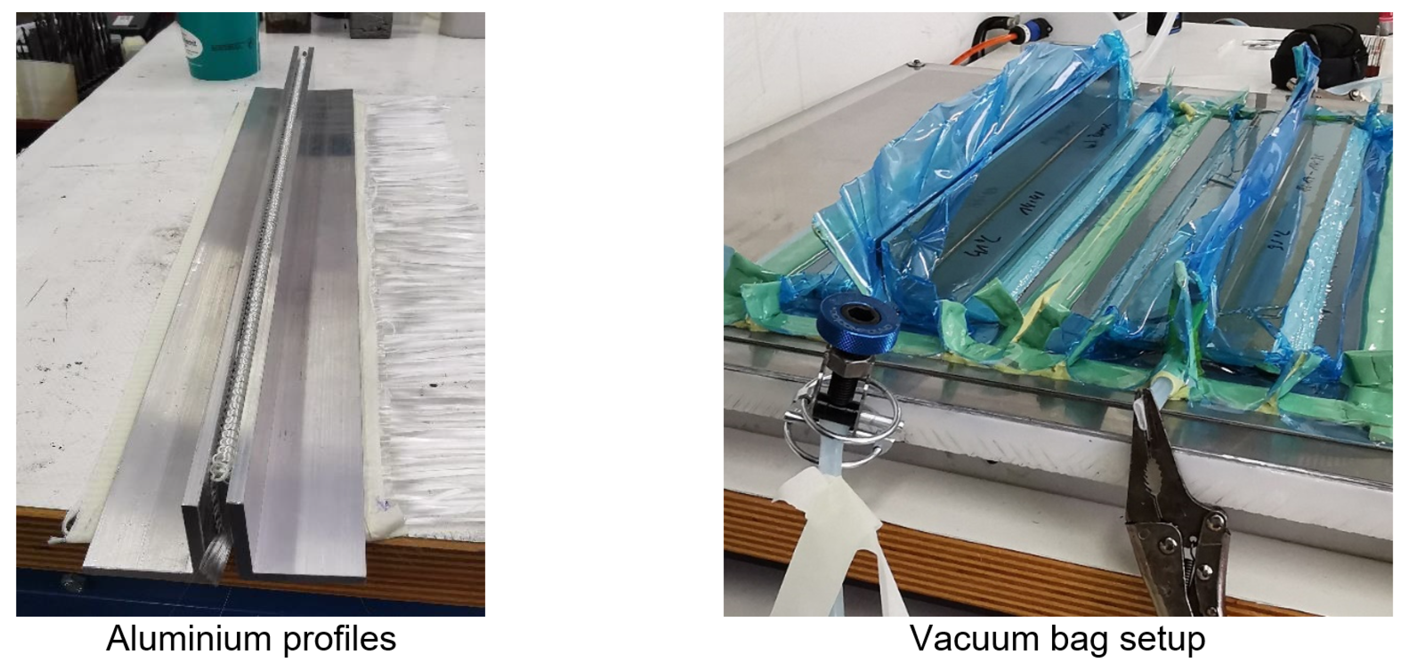
2.2. Manufacturing of Fabrics and Composite

Three variants of BWKF were chosen for manufacturing and testing: a 2-layer BWKF (0°/90°), a 4-layer asymmetric BWKF (0°/90°/0°/90°) and an integral 4-layer BWKF (see Figure 3). All BWKF are manufactured on a modified flatbed weft-knitting machine Aries 3D of manufacturer Steiger Participations Sa. (Vionnaz, Switzerland). Both 2- and 4-layer asymmetric BWKF are used for textile physical tests and production of FRP specimens for coupon level tests. Those FRP specimens are manufactured with three configurations of 2- and 4-layer fabrics, FRP-C1, FRP-C2 and FRP-C3 (compare Table 2). The integral 4-layer BWKF is used as preform for T-shaped FRP samples only. The purpose of testing the different stacking order configurations is to find out the optimized structure in the sense of cost and mechanical performance.
A vacuum-assisted resin transfer molding (VARTM) process is carried out to consolidate the FRP samples, which exhibit a flat shape. The VARTM process is a modified resin transfer molding (RTM) process. During the original RTM process, semi-finished textiles are impregnated by injecting the reactive resin under pressure. In the VARTM process, air is additionally evacuated at the risers before injecting the reaction resin. This can facilitate the injection of the reactive resin from the gate through the textile preform to the risers. Before positioning the textile reinforcement, the plate mold is cleaned with acetone and applied with release agent (Loctite 700NC) to facilitate demolding. The textile reinforcements are then carefully inserted into the plate mold, and the two mold halves are closed. The reaction resin is then injected under pressure (maximum 6 bar) while the mold is heated. The composites are de-molded after curing them under pressure of 6 bar for at least 12 h. Before testing, the composites are post-cured at 80 °C for 15 h. This allows the reaction resin to be fully cross-linked to achieve its maximum strength.
The T-shaped rib-stiffened FRP is produced with vacuum assisted resin infusion (VARI) process based on three different BWKF preforms (cf. Figure 5). In contrast to VARTM, VARI uses one mold half and vacuum bag instead of two mold halves. For the consolidation of T-shaped FRP, additional aluminum profiles are necessary (cf. Figure 6). Table 3 gives the dimensions of the T-shaped FRP specimens for bending tests. The three variants of rib-stiffened FRP are named after their length, L, and rib height, H; e.g., T300-33 has a length of 300 mm and a rib height of 33 mm. Any variant in Table 3 can be produced from BWKF with one of the three constructions presented in Figure 5. Three different constructions are established for the T-shaped samples: 4 by 2-layer BWKF (named FRP-T1), 2 by 4-layer BWKF (FRP-T2), and an integral 4-layer BWKF with a 2-layer BWKF on each side (FRP-T3). A systematic testing plan for T-shaped FRP is used to reduce the number of specimens, as shown in Table 4. While other dimensions meet the nominate design requirements, the rib height H varies across different specimens. In particular, the rib height of variant T120-33 with a 4 × 2-layer BWKF setup is 38.4 mm on average.

2.3. Testing Methods

Flat fabrics are tested according to available standards: thickness (DIN EN ISO 5084), area mass density (DIN EN 12127), and loop length (DIN EN 14970). Tensile strength of yarns is tested on a tensile testing machine Zwick Z100 (Zwick GmbH & Co. KG, Ulm, Germany), according to the standard ISO 3341. The distance between two clamps is 500 mm. A pre-tension of 0.5 cN/tex is applied to the yarn. An optical extensometer records the strain of the yarn during test. Tensile strength of fabric is tested on the same test machine Zwick Z100 according to the standard DIN EN ISO 13934-1. The test specimens are 300 × 50 mm2, the distance between two clamps is 200 mm, and the test speed is 20 mm/min. Strain of the fabrics during the test is also measured by an optical extensometer.
Following coupon tests of FRP specimens are carried out: fiber volume content (DIN 1172), tensile test (DIN EN ISO 527-4), 4-point bending test (DIN EN ISO 14125–Method B) and interlaminar shear strength test–ILSS (EN ISO 14130) (cf. Figure 7). Strain of FRP specimens in tensile tests is measured by an optical extensometer. Specimen dimensions are 25 mm × 250 mm (tensile test), 15 mm × 60 mm (4-point-bending test) and 15 mm × 30 mm (ILSS). As the support length in ILSS test (15 mm) is significantly shorter than in 4-point bending test (45 mm), failure of FRP specimen due to shear stress is expected. Before testing, all specimens are stored under normalized climate conditions at 23 °C room temperature and relative humidity of 50% for at least 24 h according to DIN EN ISO 291. Thickness of specimens is 3.2 mm (±0.1 mm).
To evaluate the structural stiffness and strength of T-shaped FRP specimens under bending load, 3-point bending tests according to DIN 14125 (method A) are conducted while special support and pressing tool are used (cf. Figure 8). Different support lengths are applied for the specimens with different lengths, according to Table 3. The fiber volume content of the T-shaped FRP samples is also tested according to DIN 1172.

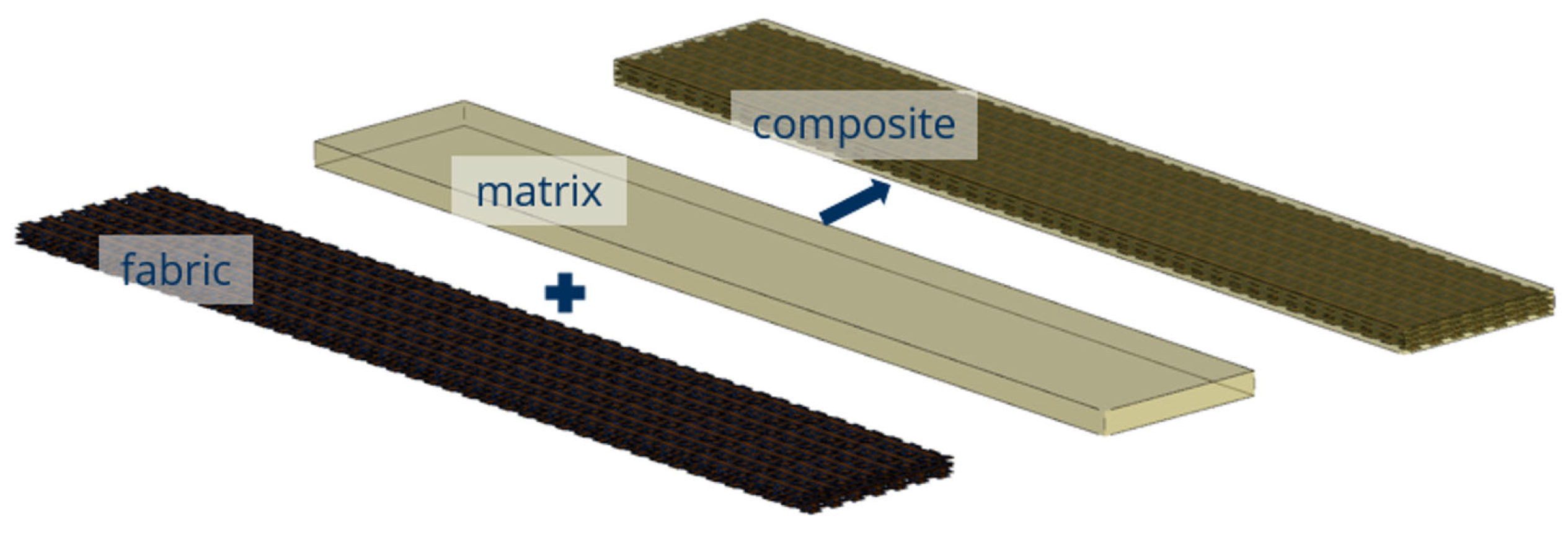
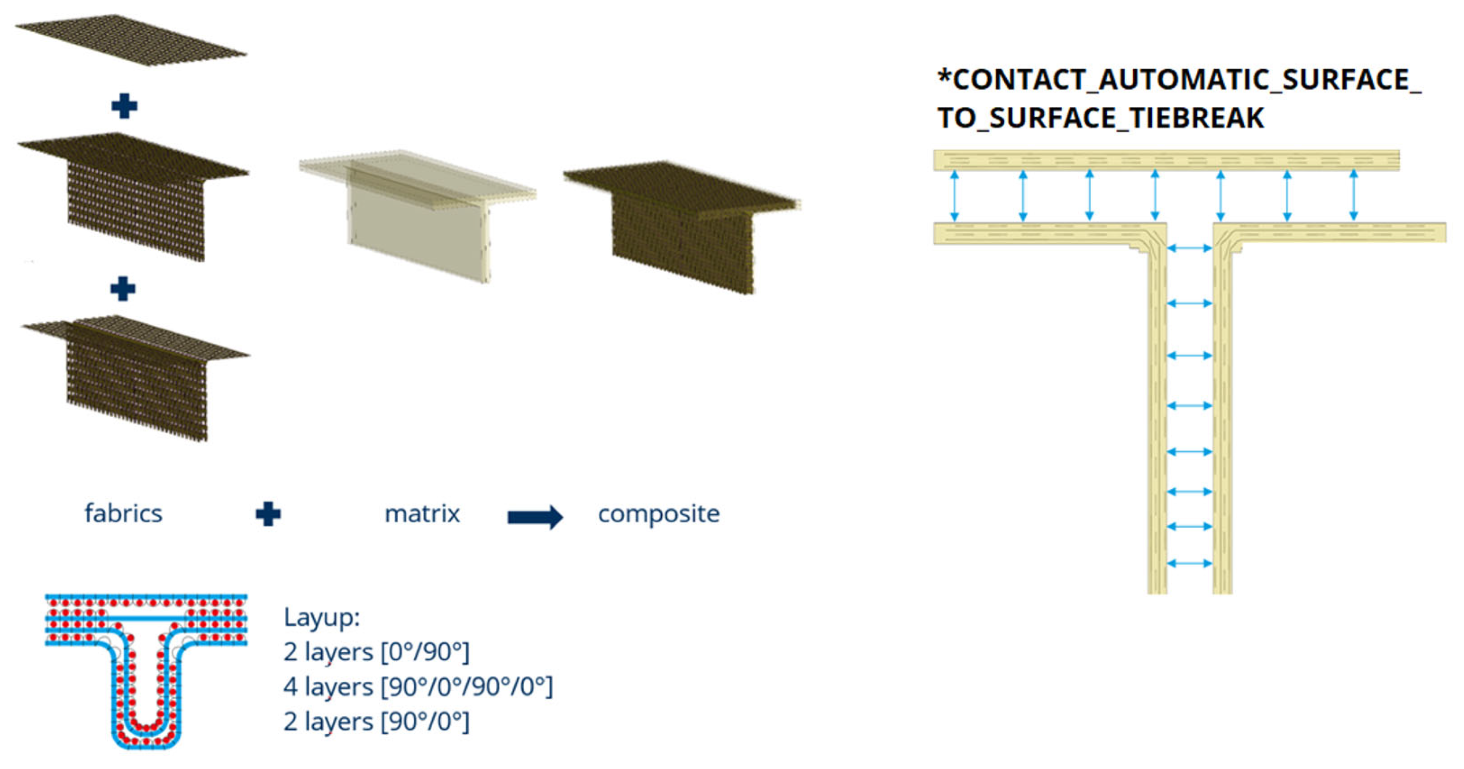
2.4. Modelling Methods

A finite element model of the BWKF composite was developed, where the BWKF is modeled on the meso-scale (Figure 9). In this model, the shell elements for the reinforcing rovings are adopted unchanged from the textile model, for which the modeling method was presented previously [58]. Both geometrical mesh and material models of reinforcing rovings are without further modification. The material model for reinforcing rovings is MAT_ELASTIC (MAT_001) of LS-DYNA, which is an isotropic hypoelastic material. A fully integrated 2D conventional shell element (ELFORM = 16) is used. Residual stresses eventually induced by thermal conditions in the process are not considered. For further details of the textile model, please refer to [58]. The adoption of geometrical mesh from the textile model allows the lay-up of BWKF to be modeled accurately for each variant (Figure 10). However, the beam elements are removed from the fabric model because the influence of stitch yarn on delamination resistance is later implemented with a contact element. The epoxy matrix is modeled with solid elements and linear elastic material based on the material parameters provided by the manufacturer (Table 1). The solid element mesh is a combination of 8-point hexahedron elements (ELFORM = 2 in LS-DYNA) and S/R quadratic tetrahedron elements (ELFORM = 4). For variants 1, 2, 3 and 5, only hexahedron elements are used.
To model the FRP in this paper, a penalty-based coupling is established between coupled nodes of shell and solid elements as an implementation of the Domain Superposition Technique (DST) [13,60]. In a penalty-based coupling, such as that implemented in LS-DYNA code, “a penalty string is attached between coupling points on shell and in the solid element. The stiffness of this penalty string is calculated based on the geometric mean of shell and solid’s bulk modulus. The magnitude of this coupling force can be controlled using a penalty string stiffness scale factor” [61]. Thus, strength of the interface between fiber and matrix can be calibrated through this penalty string stiffness scale factor. However, debonding still cannot be described. By calibrating the break elongation of shell elements, the tensile strength of FRP specimen can be described. However, the non-linearity of force–strain curve (by area near the end of test) due to the progressive damage cannot be simulated accurately as no treatment for this phenomenon is implemented (cf. Figure 13).
In order to validate the meso-scale model, tensile test simulations of BWKF and FRP are carried out. The boundary conditions are set according to the test standards. In the BWKF tensile test model, the nodes on one side of the shell elements are fixed in all translational movements, while the nodes on the other side are only fixed in translational movements in x- and z-direction. These nodes are then pulled with a constant velocity along the y-direction, which is the main direction of the specimen (cf. Figure 15). Similar boundary conditions are applied in the FRP tensile test model, where the nodes of both shell and solid elements are included.
Certain load conditions and specimen dimensions of the T-shaped FRP cause a failure due to matrix cracking. Thus, including failure criteria for matrix cracking is necessary for a reasonable prediction of stiffness and strength of the T-shaped FRP. Failures can be initiated by failure of fiber, matrix or interface between them (debonding). Matrix cracking can be initiated by matrix break under normal loading (tensile or compression) and shear loading. With the help of a tiebreak contact in LS-DYNA between solid element surfaces, crack initiation due to normal and shear components is modeled [61]. This contact failure model is applied to describe the delamination between composite layers, not for the debonding between fiber and matrix. The failure criterion is described as follows:
σ N F L S 2 + τ S F L S 2 1
where σ is tensile normal stress (only tensile stress counts, compression stress is treated as zero). Only failure mode I crack opening is taken into account, as failure due to compression is excluded from this contact failure formulation. The shear stress |τ| represents max(|τ⊥∥|, |τ⊥⊥|). Thus, there is no distinction between delamination mode II and mode III failure. NFLS and SFLS are normal failure stress and shear failure stress, respectively. Any tie contact meeting the requirement of failure criterion (1) will be excluded in the next computation step. Thus, cracking at that contact position is modeled.
The parameter NFLS is also known as mode I fracture toughness. The setting of the NFLS parameter in the FEM model is calibrated based on experimental and simulation results of 3-point bending tests of T-shaped specimens. In this 3-point bending test of the T-shaped FRP, the test specimens are cracked open (as shown in Figure 8), which helps to calibrate the NFLS parameter accordingly. FEM model of 3-point bending test of T-shaped FRP specimen is thus built to serve this purpose. The construction of the FEM model for T-shaped FRP with an interface between the solid elements for the surface-to-surface tiebreak contact formulation is shown in Figure 11.
The parameter SFLS is taken directly from the test results of the ILSS tests. Thus, the shear strength τ⊥∥ (or mode II in-plane fracture toughness) and shear strength τ⊥⊥ (or mode III out-of-plane fracture toughness) share the same value in the model. Only the minimum value of both directions is used to avoid an overestimation.
In comparison to modeling composite layers homogeneously with shell elements and coupling these shells with delamination criteria such as in [17,62,63,64,65,66], modeling reinforcing roving and matrix separately in this paper allows predicting the mechanical behavior of further variations of reinforcing yarns and/or matrix. An example might be carbon fiber rovings in a thermoplastic matrix. Additionally, as reinforcing rovings are modeled separately, the influence of their complex path within the composite structure can be taken into account.

3. Results

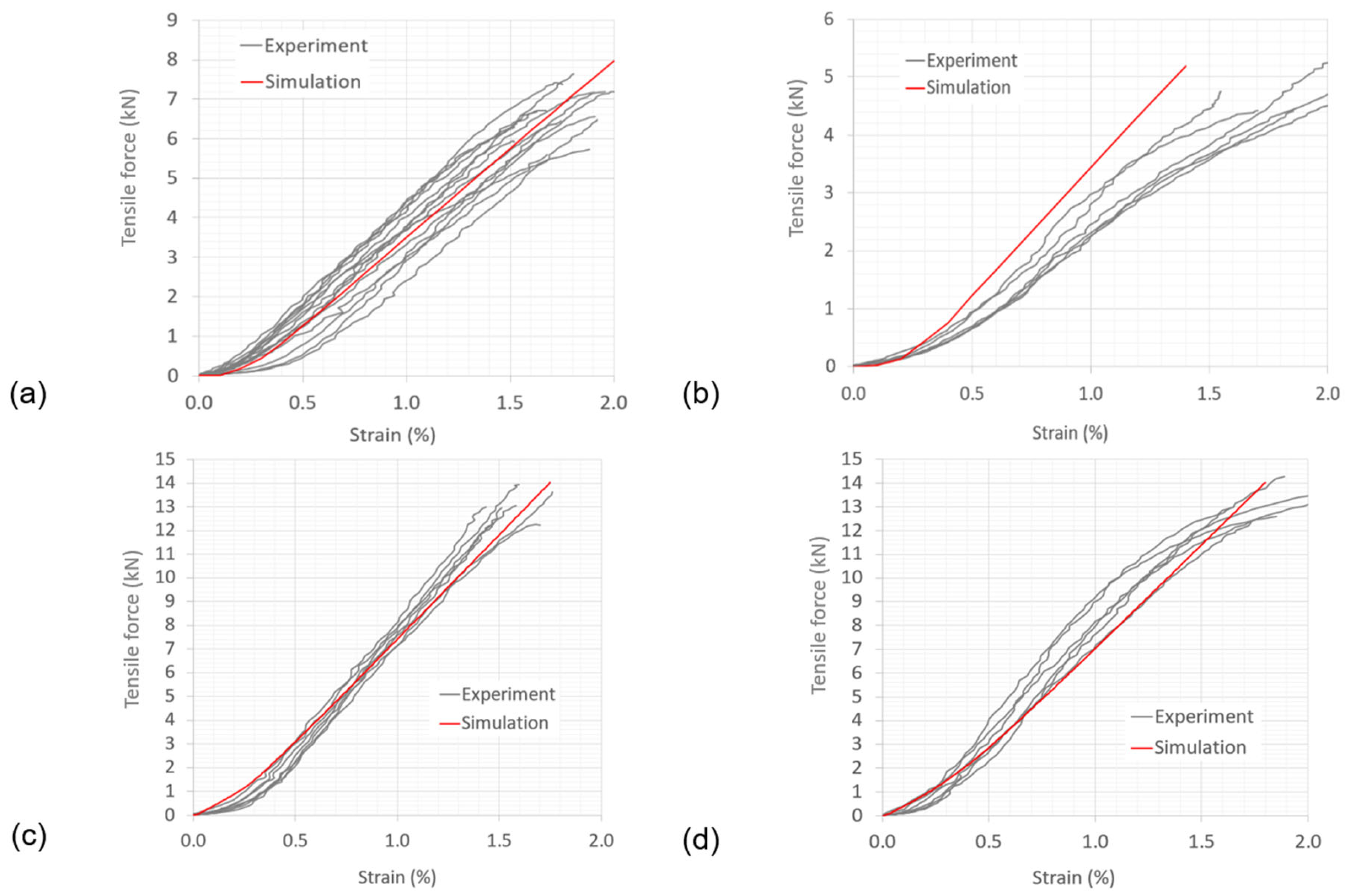
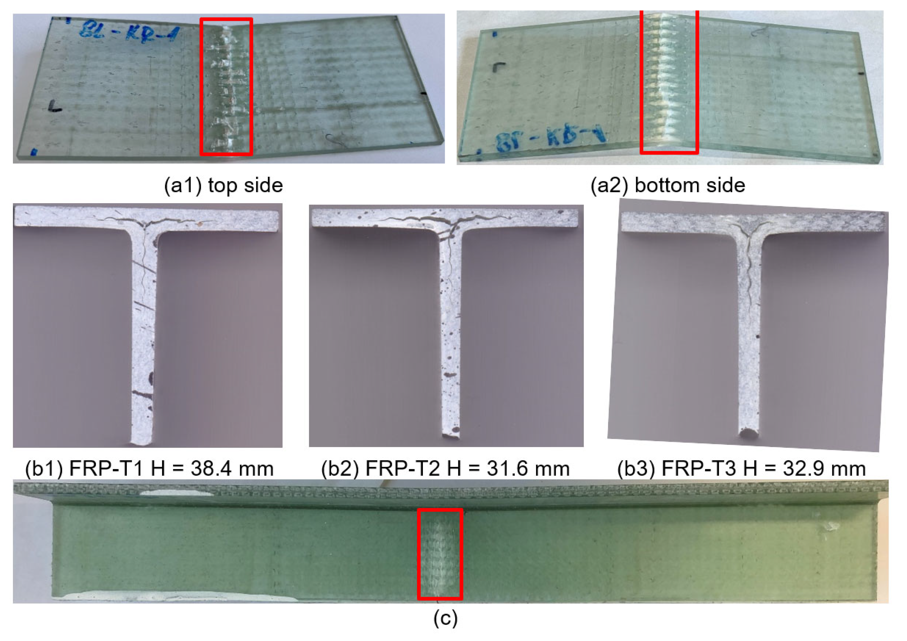
3.1. Experimental Results

The tensile strength of yarns is 574 ± 22 N and 91 ± 4 N for GF 1200 tex and GF 2 × 68 tex, respectively. Elongation at the break of the yarns is 1.8 ± 0.1% and 2.5 ± 0.1% for GF 1200 tex and GF 2 × 68 tex, respectively. Table 5 summarizes the basic values and tensile test results of the fabrics. Figure 12 shows the force–strain curves of the experiment and simulation of both 2-layer and 4-layer BWKF in warp and weft direction.
The fiber volume content of FRP coupon specimens is 47.0% ± 0.5% (FRP-C1), 42.6% ± 0.6% (FRP-C2) and 43.4% ± 0.6% (FRP-C3) and for the T-shaped specimens it is 55.4% (FRP-T1, average of all specimens with different rib height), 55.9% (FRP-T2) and 56.3% (FRP-T3). The mechanical test results of FRP are shown in Table 6. The Young’s modulus is calculated between the strain of 0.05% and 0.25%. Figure 13 shows the measured force-strain curves of FRP samples of coupon-level tensile tests. The material behavior is almost linear until failure, which occurs between 2.0% and 2.5% elongation.
Figure 13. Tensile test simulation results and experimental results of FRP samples.
Jcs 07 00175 g013
The results of 3-point bending tests of T-shaped FRP samples are summarized in Table 7. The specimens with different rib lengths undergo different failure modes under bending loading (Figure 14). Failure mode depends on the sample length. Short specimens (L = 120 mm) with rib height of 33 mm fail due to delamination, which is initiated by the break of matrix or debonding between matrix and fiber. At longer specimens (L = 300 mm and 400 mm) with the same rib height of 33 mm, the breakage of fibers in the center of the rib is dominant. The short specimens (L = 120 mm) show no rib fail due to the break of fibers on the tension side and matrix break on the tension and compression sides at the middle position. An explanation for the difference between short and long specimens (as well as short and long support lengths) is the lever effect. With the same rib height and at the same deformation, the fiber at the middle of the rib shows a significantly higher strain in the long specimen than in the short specimen. This leads to premature fiber breakage (Figure 14c) and a reduction in bending strength. For the short specimen, as the fiber strain in the rib builds up slowly, the failure is determined by a different mechanism: interlaminar shear. Under bending load, tensile and compression stresses occur in the fiber layers. The fiber layers above the neutral plane are compressed, while the fiber layers below the neutral plane are stretched. Furthermore, the greater the distance between the fiber layers and the neutral plane, the higher the stress. The difference between these in-plane stresses causes shear stress and leads to delamination. This delamination occurs on multiple fiber planes, but the most critical is the neutral plane, where the stress differences are likely to be greatest. Another influencing factor for T-shaped samples is the gusset (resin-rich pocket), where the fiber volume is lowest and which is located exactly near the neutral plane. These two conditions favor the initiation and propagation of cracks.
To compare the strength of FRP with different rib height (due to production), the bending strength (max. F) is standardized to a rib height of 33 mm. The standardized results in Table 7 reveal the highest strength in FRP-T3 specimens for variant T120-33, which has an integral fabric in the center. In FRP-T1 configuration with different lengths (120 mm, 300 mm and 400 mm), the standardized results show a clear decline of max. F with an increased support length in the bending test. The standardized max. F is calculated according to Equation (2). The nominal rib height H is 33 mm (Table 3). The actual rib height can be found in Table 4.
S t a n d a r d i z e d   M a x . F = M a x .   F × N o m i n a l   r i b   h e i g h t   H A c t u a l   r i b   h e i g h t   H
The crack opening in the T120-33 specimen can be seen in Figure 14b. The crack is propagated in both flange and rib areas from the gusset.

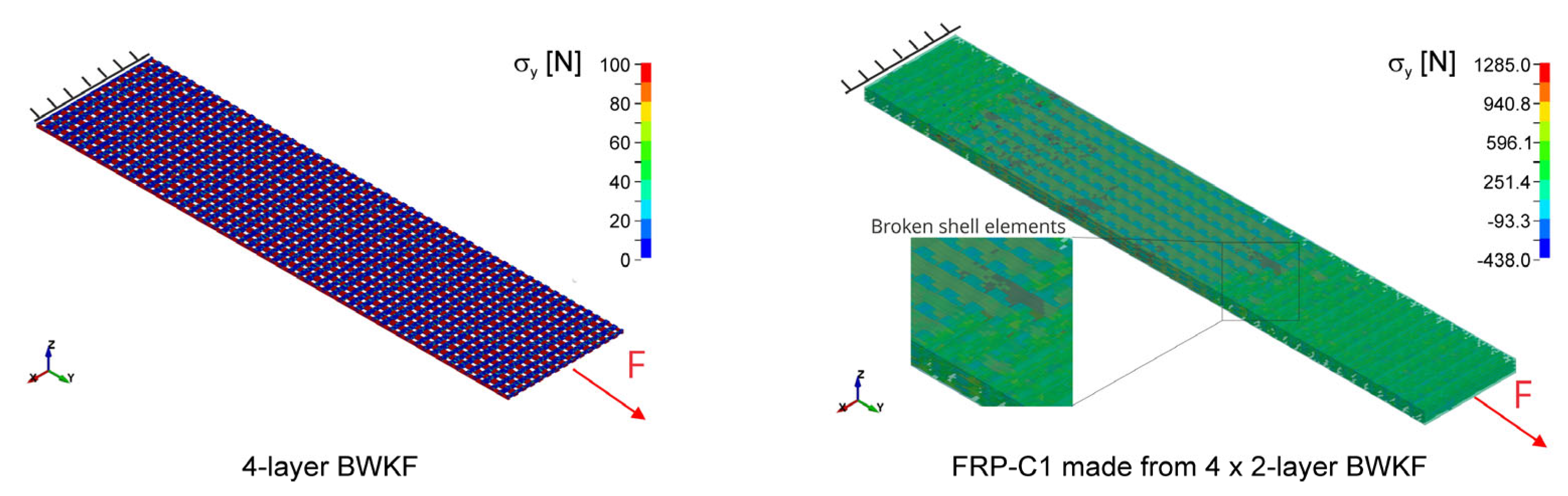
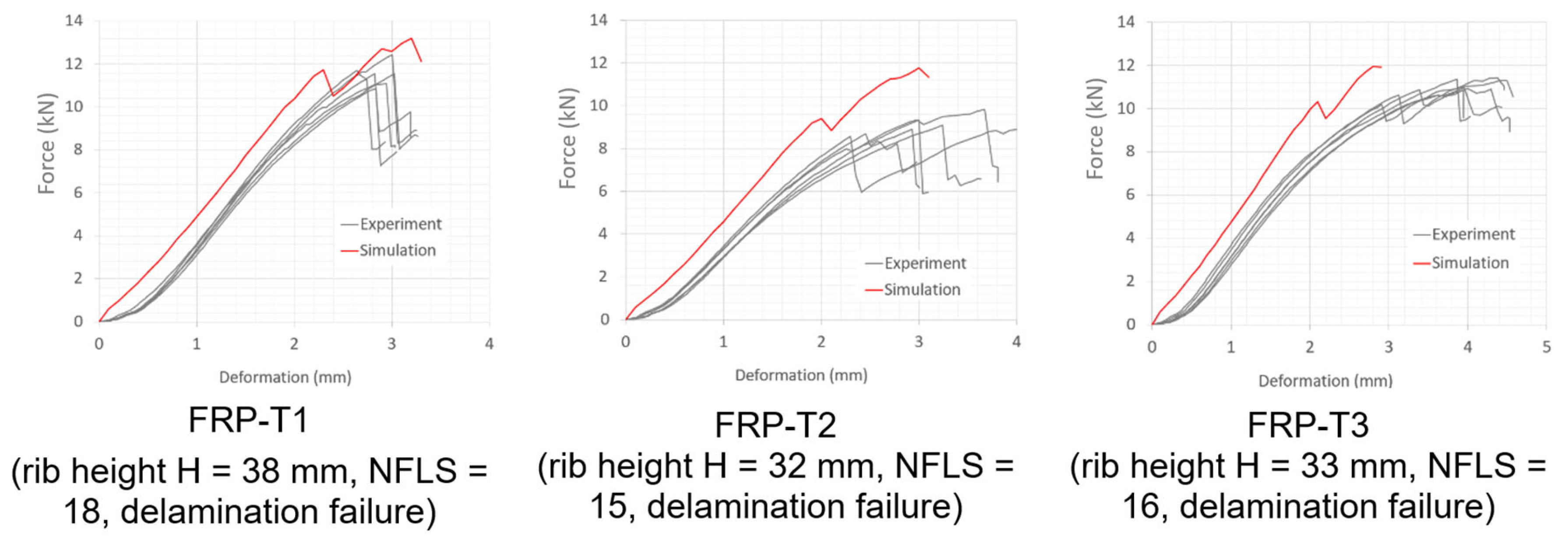
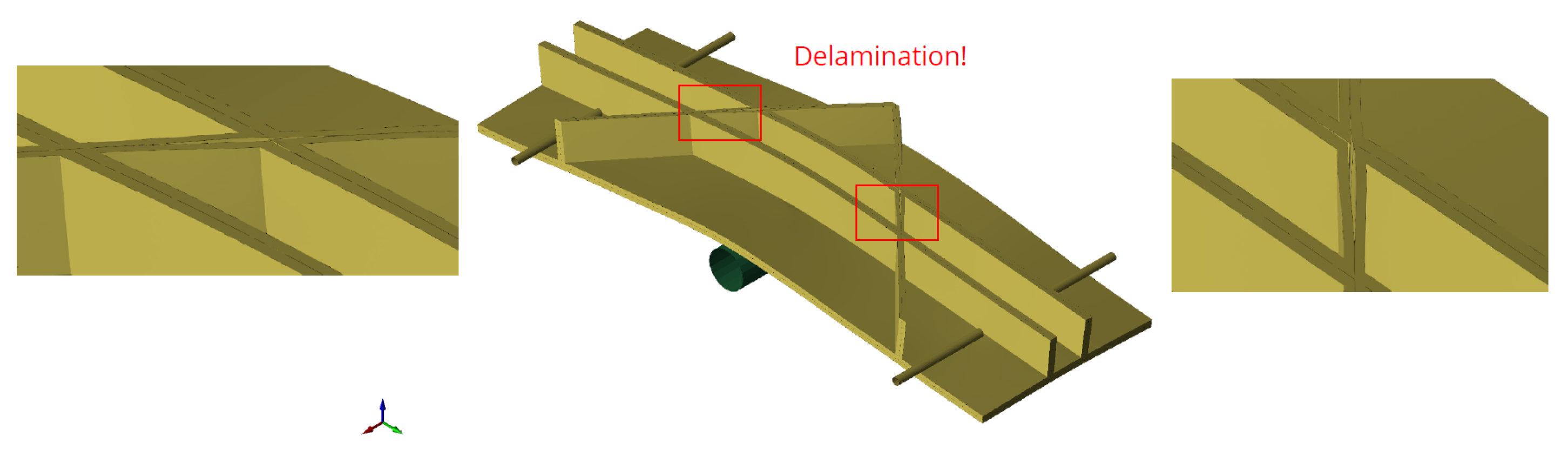
3.2. Modelling Results

Figure 15 shows the simulated tensile tests of a 4-layer fabric and an FRP coupon sample. The simulated force–strain behavior is compared to the experiments in Figure 12 (fabric) and Figure 13 (composite). The model reproduces the non-linear behavior of the fabrics at low strains very well, which is due to the crimp of the weft and warp yarns. The linear elastic material model used for the yarns is a very good approximation of the real material behavior. Small deviations occur at strains above 1% when the 4-layer fabric behaves non-linearly in the weft direction. Figure 13 compares the simulated tensile behavior with coupon-level tests of real samples. The simulations show very good agreement with the experimental tests for the three variants with different fabric setups, FRP-C1, FRP-C2 and FRP-C3. Those results of the tensile behavior validate the fabric and composite models at the coupon level.
Figure 15. Tensile test simulations with meso-scale model of BWKF and FRP.
Jcs 07 00175 g015
Figure 16 provides results of FRP T120-0 samples in configurations FRP-T1 and -T3, i.e., FRP samples with a length of 120 mm and no rib. Model predictions are identical for both configurations with observed matrix and fiber breakage. Compared to the T-shaped samples, the maximum force is low and deformation is high (above 10 mm), which is due to the flat shape of the samples. The experimental bending tests reveal differences in bending strength between the two configurations, but the simulation model cannot describe these differences. This is due to simplifications of the meso-scale FEM model. Although it correctly replicates the structure of the reinforcing layers with shell elements, it is still far from the reality in which the fibers are distributed across the thickness direction. Only a micro-scale model can meet this requirement.
Figure 17 shows the simulated bending test of the T-shaped FRP variant T120-33 with fabric construction FRP-T1, FRP-T2 and FRP-T3 at 3 mm deformation (tools are blended out by the comparison of three variants). Since the actual rib height H is different for each variant, each FEM model is adapted to the actual sample size. In FEM models, all variants show crack openings in both the flange and rib area at 3 mm deformation (Figure 17). In the rib, the size of the crack is large and varies between variants. The crack length in the flange area is smaller in comparison with the rib area for all variants. At 4 mm deformation (for example, FRP-T1, as shown in Figure 17), the crack in the flange area is widely opened, which is in agreement with the experimental observation (Figure 8).
Figure 18 compares the force–deformation behavior of FRP T120-33 in real and simulated 3-point bending tests. The three different preform constructions are presented in the figure. The simulation model shows a good correlation to experiments for stiffness and strength. However, the non-linear behavior of the force–deformation curves at the start of the test by short-length support is not described correctly, and deviations are unavoidable. The non-linearity can be caused by the progressive Mode I crack opening and Mode II in-plane fracture failure due to shear stress by the short support length. By the long support length test results, the non-linearity of force–strain curves are not significant, as shown in Figure 19.
It is no surprise that NFLS is the largest with 4 × 2-layer BWKF construction (FRP-T1). In this construction, the proportion of stitch yarn in the thickness direction is the largest (4×) compared to the other two, i.e., the highest fiber volume in the thickness direction. 2 × 4-layer BWKF (FRP-T2) has the least stitch yarn in the thickness direction (only 2×), resulting in the smallest NFLS. In the middle is the integral 4-layer BWKF version with 3× stitch yarn system in the flange and 4× stitch yarn system in the rib.
To investigate the leverage effect, both experiments and simulations were carried out using longer T-shaped components (300 mm and 400 mm) with a 4 × 2-layer BWKF construction (FRP-T1). The dominant failure is the fracture of the rib due to tensile stresses (Figure 19). Although the failure mechanism and strength can be predicted correctly, the model underestimates the stiffness of the long FRP specimens. Since the FEM model can describe the mechanical behavior of T-shaped FRP components with BWKF reinforcement in both failure scenarios (delamination as shown in Figure 17 and break of yarn in rib as shown in Figure 19) with a moderate relative error in bending strength and larger error in deformation (Table 8), it can be further used to predict the behavior of other rib stiffened components with different dimensions and configurations, using the deformation value with caution. The error is calculated according to Equation (3). The reason for this deviation is the simplification of the model at the current level:
  • The failure mechanism debonding has not been taken into account.
  • Failure of the fiber–matrix interface due to compression is neglected.
  • Mode II in-plane fracture toughness in warp and weft direction share the same value.
  • Mode III out-of-plane fracture is not included in the model.
Due to the manual lay-up, some imperfections such as fiber distortion or disorientation can occur within the T-shaped specimen, especially noticeable in long specimens, which lead to deviation of the 3-point bending experiment results in Figure 19.
e r r o r   % = S i m u l a t i o n A v e r a g e   o f   e x p e r i m e n t A v e r a g e   o f   e x p e r i m e n t × 100

3.3. Application of the Models to the Analysis of Further Variants

After validation, the models are used to predict the behavior of rib-stiffened FRP with further constructions and dimensions. FEM models of combined variants of rib-stiffened FRP are created to support the research and development process of direct manufacturing of 3D preforms for rib-stiffened FRP with more complex rib designs (as shown in Figure 1). The result of the direct manufacturing is an integral 4-layer BWKF. Suppose that this 4-layer BWKF is further used for the construction of FRP with the lay-up of 2-layer/integral 4-layer/2-layer BWKF. These FEM models are manually built up, as the yarn path is known (e.g., variant 3 as shown in Figure 20). The advantage of this manufacturing technique is that the thread can run continuously in the rib in many directions, which increases the stiffness in different directions at the same time (e.g., variant 4 as shown in Figure 21).
A simulative investigation is carried out for other variants of shell–rib structure with more complex geometries of the ribs. Variants 0–7, as displayed in Figure 1, are analyzed in three-point bending simulations. Dimensions of these rib-stiffened FRP are 100 mm in width, 300 mm in length and 20 mm in rib height. The support length for the bending tests is 225 mm. Flange and rib thickness are 4 mm. Figure 22 shows the predicted force–deformation curves of 3-point bending tests with a maximum deformation of 10 mm. Variants without rib in 0° direction, i.e., variants 0, 2, 3 and 6, exhibit a very small stiffness for bending in 0° direction. The influence of ribs in perpendicular and diagonal directions on the stiffness of FRP in the tested direction is not significant. Variants 1 and 4 have similar force-deformation curves, as both of them have ribs in 0° direction, with yarn failure predominating in the rib.
In variant 5, a crack opening of the matrix in the middle of the diagonal rib occurs (Figure 23). This leads to a disturbance of the force-deformation curve and, thus, to a noticeable reduction in bending strength. Such a large crack only occurs when both of the following conditions are fulfilled thread breakage in the rib in the 0° direction and delamination of the rib in the diagonal direction. Due to the position of the diagonal rib, the stress normal to the diagonal rib builds up fast, which can lead to premature delamination of the diagonal rib. Experimental should be carried out to confirm this phenomenon. With double ribs in the 0° direction, variant 7 has a significantly higher stiffness than other variants. The failure mode is delamination of the diagonal rib, as in variant 5. However, the cracks in variant 7 are not as wide open as in variant 5 (see Figure 24). In general, the FEM model provides logical predictions for the base and combination variants. However, some predictions should be verified by actual experiments, which would help to suggest further improvements to the FEM model.

4. Conclusions

Potential industrial applications of rib-stiffened shell structures include highly load-bearing rib-stiffened FRP components in rail vehicle construction, automotive and mechanical engineering, hull structures in ship construction as well as load-bearing structures in aerospace (e.g., aircraft fuselage or isogrid structures). An excellent textile technology for manufacturing net shape shell–rib structures is the weft-knitting technology. It enables the manufacturing of integral preforms with a multilayer structure and reinforcing yarns in the weft and warp directions. The orientation of the rib can be adapted to the component requirements. An FEM model is very useful for the development of such rib-stiffened FRP components, as the mechanical behavior of a rib-stiffened FRP with predetermined dimensions and configurations can be predicted without the need to produce a prototype. The meso-scale approach, where yarn and matrix are modeled separately, enables FEM-based prediction of the change of mechanical behavior of FRP depending on reinforcing fiber and matrix. The assistance of the FEM model saves time, material and costs during the development process. The developed meso-scale model can adequately describe the mechanical behavior of T-shaped FRP components with BWKF reinforcement. It is able to predict delamination and yarn breakage with a moderate deviation for bending strength and a larger deviation for deformation. The current model can also predict buckling and torsional stiffness. However, the current FEM model can describe the most important FRP failure mechanisms and provides good predictions of the bending behavior. There is still room for further improvement, as the deviation of the predicted value is still great in comparison to the experimental data, namely circa 20% at bending strength and 50% at the prediction of deformation. Further failure mechanisms, such as debonding, should be taken into account. The contact interface should also be improved, where mode II in-plane fracture toughness in warp and weft direction can be set separately. Further improvement of the contact interface can be made, e.g., measuring and modeling the mode III out-of-plane fracture toughness. The ILSS test results show multiple shear failures along the thickness direction. Thus, increasing the number of contact interfaces along the thickness direction can improve the accuracy of the model but also involves additional computational costs.

Author Contributions

Conceptualization, M.Q.P., Q.B. and T.G.; methodology, M.Q.P. and T.G.; software, M.Q.P. and T.G.L.; validation, M.Q.P., Q.B. and D.R.; formal analysis, M.Q.P., Q.B. and D.R.; investigation, M.Q.P., Q.B. and D.R.; resources, M.Q.P., Q.B. and D.R.; data curation, M.Q.P., T.G.L., Q.B. and D.R.; writing—original draft preparation, M.Q.P., Q.B. and T.G.; writing—review and editing, D.R., T.G.L., E.H., W.T., C.C. and T.G.; visualization, M.Q.P., T.G.L. and Q.B.; supervision, E.H., W.T., C.C. and T.G.; project administration, Q.B., E.H. and T.G.; funding acquisition, Q.B., E.H., W.T., C.C. and T.G. All authors have read and agreed to the published version of the manuscript.

Funding

The IGF research project 20793 BR of the Forschungsvereinigung Forschungskuratorium Textil e.V. was funded through the AiF within the program for supporting the “Industrielle Gemeinschaftsforschung (IGF)” from funds of the Federal Ministry For Economic Affairs And Climate Action (BMWK) by a resolution of the German Bundestag. The authors would like to thank the above-mentioned institutions for the provided financial support.

Data Availability Statement

Data available on request.

Acknowledgments

The authors would like to acknowledge all enterprises of the project-related committee for their professional collaboration during the IGF project.

Conflicts of Interest

The authors declare no conflict of interest.

References

  1. Palmer, R. Techno-Economic Requirements for Composite Aircraft Components: Innovative Composite Aircraft Primary Structure. In Proceedings of the FIBER-TEX 1992: The Sixth Conference on Advanced Engineering Fibers and Textile Structures for Composites, Philadelphia, PA, USA, 27–29 October 1992. [Google Scholar]
  2. Crosky, A.; Grant, C.; Kelly, D.; Legrand, X.; Pearce, G. 4—Fibre placement processes for composites manufacture. In Advances in Composites Manufacturing and Process Design; Boisse, P., Ed.; Woodhead Publishing: Sawston, UK, 2015; pp. 79–92. ISBN 978-1-78242-307-2. [Google Scholar]
  3. Hasani, H.; Hassanzadeh, S.; Abghary, M.J.; Omrani, E. Biaxial weft-knitted fabrics as composite reinforcements: A review. J. Ind. Text. 2017, 46, 1439–1473. [Google Scholar] [CrossRef]
  4. Le Phuc, B. Konstruktive und Technologische Weiterentwicklung der Flachstricktechnik zur Herstellung von Multilayer-Gestricken mit bis zu neun Verstärkungslagen; TUD Press: Dresden, Germany, 2006; ISBN 3-938863-41-2. [Google Scholar]
  5. Abounaim, M.S.M. Process Development for the Manufacturing of Flat Knitted Innovative 3D Spacer Fabrics for High Performance Composite Applications. Ph.D. Thesis, Technische Universität Dresden, Dresden, Germany, 2010. [Google Scholar]
  6. Bollengier, Q.; Wieczorek, F.; Hellmann, S.; Trümper, W.; Cherif, C. One-step manufacturing of innovative flat-knitted 3D net-shape preforms for composite applications. IOP Conf. Ser. Mat. Sci. Eng. 2017, 254, 42007. [Google Scholar] [CrossRef]
  7. Bollengier, Q.; Trümper, W.; Cherif, C. Integral gefertigte 3D-Schale-Rippen-Strukturen auf Basis von Mehrlagengestricken. Tech. Text. 2020, 62, 113–115. [Google Scholar]
  8. Różyło, P.; Wysmulski, P.; Falkowicz, K. Fem and Experimental Analysis of Thin-Walled Composite Elements Under Compression. Int. J. Appl. Mech. Eng. 2017, 22, 393–402. [Google Scholar] [CrossRef]
  9. Wysmulski, P.; Debski, H.; Falkowicz, K.; Rozylo, P. The influence of load eccentricity on the behavior of thin-walled compressed composite structures. Compos. Struct. 2019, 213, 98–107. [Google Scholar] [CrossRef]
  10. Khandan, R.; Noroozi, S.; Sewell, P.; Vinney, J. The development of laminated composite plate theories: A review. J. Mater. Sci. 2012, 47, 5901–5910. [Google Scholar] [CrossRef]
  11. Hinton, M.; Soden, P.D.; Kaddour, A.-S. Failure Criteria in Fibre Reinforced Polymer Composites: The World-Wide Failure Exercise; Elsevier Ltd.: Kidlington, UK, 2004. [Google Scholar]
  12. Camanho, P.P.; Hallett, S.R. Numerical Modelling of Failure in Advanced Composite Materials; Woodhead Publishing: Sawston, UK, 2015; ISBN 9780081003428. [Google Scholar]
  13. Hübner, M.; Staiger, E.; Küchler, K.; Gereke, T.; Cherif, C. Simulation of patched woven fabric composite structures under tensile load. Tekstilec 2016, 59, 175–181. [Google Scholar] [CrossRef]
  14. Stig, F.; Hallström, S. A modelling framework for composites containing 3D reinforcement. Compos. Struct. 2012, 94, 2895–2901. [Google Scholar] [CrossRef]
  15. Lomov, S.; Ivanov, D.; Verpoest, I.; Zako, M.; Kurashiki, T.; Nakai, H.; Hirosawa, S. Meso-FE modelling of textile composites: Road map, data flow and algorithms. Compos. Sci. Technol. 2007, 67, 1870–1891. [Google Scholar] [CrossRef]
  16. Stig, F.; Hallström, S. Spatial modelling of 3D-woven textiles. Compos. Struct. 2012, 94, 1495–1502. [Google Scholar] [CrossRef]
  17. Wang, Y.; Soutis, C. A Finite Element and Experimental Analysis of Composite T-Joints Used in Wind Turbine Blades. Appl. Compos. Mater. 2018, 25, 953–964. [Google Scholar] [CrossRef]
  18. Le Page, B.H.; Guild, F.J.; Ogin, S.L.; Smith, P.A. Finite element simulation of woven fabric composites. Compos. Part A Appl. Sci. Manuf. 2004, 35, 861–872. [Google Scholar] [CrossRef]
  19. LLorca, J.; González, C.; Molina-Aldareguía, J.M.; Segurado, J.; Seltzer, R.; Sket, F.; Rodríguez, M.; Sádaba, S.; Muñoz, R.; Canal, L.P. Multiscale modeling of composite materials: A roadmap towards virtual testing. Adv. Mater. 2011, 23, 5130–5147. [Google Scholar] [CrossRef]
  20. Barbero, E.J.; Lonetti, P.; Sikkil, K.K. Finite element continuum damage modeling of plain weave reinforced composites. Compos. Part B 2005, 37, 137–147. [Google Scholar] [CrossRef]
  21. Daggumati, S.; van Paepegem, W.; Degrieck, J.; Xu, J.; Lomov, S.V.; Verpoest, I. Local damage in a 5-harness satin weave composite under static tension: Part II—Meso-FE modelling. Compos. Sci. Technol. 2010, 70, 1934–1941. [Google Scholar] [CrossRef]
  22. Cox, B.N.; Carter, W.C.; Fleck, N.A. A binary model of textile composites—I. Formulation. Acta Metall. Mater. 1994, 42, 3463–3479. [Google Scholar] [CrossRef]
  23. Li, D.; Fang, D.; Jiang, N.; Xuefeng, Y. Finite element modeling of mechanical properties of 3D five-directional rectangular braided composites. Compos. Part B 2011, 42, 1373–1385. [Google Scholar] [CrossRef]
  24. Zhang, C.; Curiel-Sosa, J.L.; Bui, T.Q. Meso-scale finite element analysis of mechanical behavior of 3D braided composites subjected to biaxial tension loadings. Appl. Compos. Mater. 2019, 26, 139–157. [Google Scholar] [CrossRef]
  25. Pickett, A.K.; Sirtautas, J.; Erber, A. Braiding Simulation and Prediction of Mechanical Properties. Appl. Compos. Mater. 2009, 16, 345–364. [Google Scholar] [CrossRef]
  26. Liu, Z.; Hou, Y.; Zhao, Q.; Li, C. A novel surrogate modeling strategy of the mechanical properties of 3D braided composites. Chin. J. Aeronaut. 2020, 33, 2589–2601. [Google Scholar] [CrossRef]
  27. Gholami, A.; Melenka, G.W. Finite element analysis of 2-D tubular braided composite based on geometrical models to study mechanical performances. Mech. Adv. Mater. Struct. 2021, 29, 7542–7558. [Google Scholar] [CrossRef]
  28. Gu, B. A microstructure model for finite-element simulation of 3D rectangular braided composite under ballistic penetration. Philos. Mag. 2007, 87, 4643–4669. [Google Scholar] [CrossRef]
  29. Dhimole, V.K.; Chen, Y.; Cho, C. Modeling and Two-Step Homogenization of Aperiodic Heterogenous 3D Four-Directional Braided Composites. J. Compos. Sci. 2020, 4, 179. [Google Scholar] [CrossRef]
  30. Li, X.; Binienda, W.K.; Goldberg, R.K. Finite-Element Model for Failure Study of Two-Dimensional Triaxially Braided Composite. J. Aerosp. Eng. 2011, 24, 170–180. [Google Scholar] [CrossRef]
  31. Zheng, H.; Zhou, C.; Yuan, Y. Meso-scale finite element modeling of moisture diffusion in 3D braided composite. Int. J. Heat Mass Transf. 2019, 129, 862–872. [Google Scholar] [CrossRef]
  32. Xu, K.; Qian, X.; Huang, R. An FEM Analysis with Consideration of Random Void Defects for Predicting the Mechanical Properties of 3D Braided Composites. Adv. Mater. Sci. Eng. 2014, 2014, 439819. [Google Scholar] [CrossRef]
  33. Yamamoto, T.; Imaoku, A.; Sakakibara, T.; Zako, M. A proposal of conventional FE-modeling for layered braided composites: Comparison of numerical results with experimental results. IOP Conf. Ser. Mater. Sci. Eng. 2018, 406, 12031. [Google Scholar] [CrossRef]
  34. Song, S.; Waas, A.M.; Shahwan, K.W.; Faruque, O.; Xiao, X. Compression Response of 2D Braided Textile Composites: Single Cell and Multiple Cell Micromechanics Based Strength Predictions. J. Compos. Mater. 2008, 42, 2461–2482. [Google Scholar] [CrossRef]
  35. Fang, G.; Wang, B.; Liang, J. A coupled FE-FFT multiscale method for progressive damage analysis of 3D braided composite beam under bending load. Compos. Sci. Technol. 2019, 181, 107691. [Google Scholar] [CrossRef]
  36. Creech, G.; Pickett, A.K. Meso-modelling of Non-Crimp Fabric composites for coupled drape and failure analysis. J. Mater. Sci. 2006, 41, 6725–6736. [Google Scholar] [CrossRef]
  37. Sirtautas, J.; Pickett, A.K.; Lépicier, P. A mesoscopic model for coupled drape-infusion simulation of biaxial Non-Crimp Fabric. Compos. Part B Eng. 2013, 47, 48–57. [Google Scholar] [CrossRef]
  38. Drapier, S.; Wisnom, M.R. Finite-element investigation of the compressive strength of non-crimp-fabric-based composites. Compos. Sci. Technol. 1999, 59, 1287–1297. [Google Scholar] [CrossRef]
  39. Yin, H.; Li, Q.; Iannucci, L. Meso-scale finite element (FE) modelling of biaxial carbon fibre non-crimp-fabric (NCF) based composites under uniaxial tension and in-plane shear. Compos. Struct. 2022, 290, 115538. [Google Scholar] [CrossRef]
  40. Carvelli, V.; Chi, T.T.; Larosa, M.S.; Lomov, S.V.; Poggi, C.; Angulo, D.R.; Verpoest, I. Experimental and numerical determination of the mechanical properties of multi-axial multi-ply composites. In Proceedings of the 11th European Conference on Composite Materials—ECCM 11, Rhodes, Greece, 31 May—3 June 2004. [Google Scholar]
  41. Ferreira, L.M.; Graciani, E.; París, F. Predicting failure load of a non-crimp fabric composite by means of a 3D finite element model including progressive damage. Compos. Struct. 2019, 225, 111115. [Google Scholar] [CrossRef]
  42. González, A.; Graciani, E.; París, F. Prediction of in-plane stiffness properties of non-crimp fabric laminates by means of 3D finite element analysis. Compos. Sci. Technol. 2008, 68, 121–131. [Google Scholar] [CrossRef]
  43. Mikhaluk, D.S.; Truong, T.C.; Borovkov, A.I.; Lomov, S.V.; Verpoest, I. Experimental observations and finite element modelling of damage initiation and evolution in carbon/epoxy non-crimp fabric composites. Eng. Fract. Mech. 2008, 75, 2751–2766. [Google Scholar] [CrossRef]
  44. Ravandi, M.; Ahlquist, S.; Banu, M. Numerical modelling of mechanical behaviour of weft-knitted carbon fiber composites. In Proceedings of the 8th European Conference for Aeronautics and Space Sciences (EUCASS), Madrid, Spain, 1–4 July 2019. [Google Scholar]
  45. Ionesi, S.D.; Ciobanu, L.; Dumitras, C.; Avadanei, M.; Dulgheriu, I.; Ionescu, I.; Loghin, M.C. FEM Analysis of Textile Reinforced Composite Materials Impact Behavior. Materials 2021, 14, 7380. [Google Scholar] [CrossRef]
  46. Hamedi, S.; Hasani, H.; Dibajian, S.H. Numerical simulating the flexural properties of 3D weft-knitted spacer fabric reinforced composites. J. Compos. Mater. 2017, 51, 1887–1899. [Google Scholar] [CrossRef]
  47. Haasemann, G.; Ulbricht, V.; Brummund, J. Modelling the mechanical properties of biaxial weft-knitted fabric reinforced. Proc. Appl. Math. Mech. 2004, 4, 193–194. [Google Scholar] [CrossRef]
  48. Pindera, M.-J.; Khatam, H.; Drago, A.S.; Bansal, Y. Micromechanics of spatially uniform heterogeneous media: A critical review and emerging approaches. Compos. Part B Eng. 2009, 40, 349–378. [Google Scholar] [CrossRef]
  49. Döbrich, O.; Gereke, T.; Cherif, C. Modelling of fibre-reinforced composites on a near micro scale: Possibilities and benefits. In Proceedings of the 10th European LS-DYNA Conference, Würzburg, Germany, 15–17 June 2015. [Google Scholar]
  50. Liu, C.; Xie, J.; Sun, Y.; Chen, L. Micro-scale modeling of textile composites based on the virtual fiber embedded models. Compos. Struct. 2019, 230, 111552. [Google Scholar] [CrossRef]
  51. Raju, K.; Tay, T.-E.; Tan, V.B.C. A review of the FE2 method for composites. Multiscale Multidiscip. Model. Exp. Des. 2021, 4, 1–24. [Google Scholar] [CrossRef]
  52. De Araújo, M.; Fangueiro, R.; Hong, H. Modelling and simulation of the mechanical behaviour of weft-knitted fabrics for technical applications. Part IV: 3D FEA model with a mesh of tetrahedric elements. Autex Res. J. 2004, 4, 72–80. [Google Scholar]
  53. De Araújo, M.; Fangueiro, R.; Hong, H. Modelling and simulation of the mechanical behaviour of weft-knitted fabrics for technical applications: Part II: 3D model based on the elastica theory. Autex Res. J. 2003, 3, 166–172. [Google Scholar]
  54. De Araújo, M.; Fangueiro, R.; Hong, H. Modelling and simulation of the mechanical behaviour of weft-knitted fabrics for technical applications: Part III: 2D hexagonal FEA model with non-linear truss elements. Autex Res. J. 2004, 4, 25–32. [Google Scholar]
  55. Duhovic, M.; Bhattacharyya, D. Simulating the deformation mechanisms of knitted fabric composites. Compos. Part A Appl. Sci. Manuf. 2006, 37, 1897–1915. [Google Scholar] [CrossRef]
  56. Döbrich, O.; Gereke, T.; Diestel, O.; Krzywinski, S.; Cherif, C. Decoupling the bending behavior and the membrane properties of finite shell elements for a correct description of the mechanical behavior of textiles with a laminate formulation. J. Ind. Text. 2013, 44, 70–84. [Google Scholar] [CrossRef]
  57. Pham, M.Q.; Döbrich, O.; Trümper, W.; Gereke, T.; Cherif, C. Numerical modelling of the mechanical behaviour of biaxial weft-knitted fabrics on different length scales. Materials 2019, 12, 3693. [Google Scholar] [CrossRef]
  58. Pham, M.Q.; Wendt, E.; Häntzsche, E.; Gereke, T.; Cherif, C. Numerical modeling of the mechanical behavior of textile structures on the meso-scale for forming process simulations of composite 3D preforms. Eng. Rep. 2020, 4, e12348. [Google Scholar] [CrossRef]
  59. Pham, M.Q.; Döbrich, O.; Mersch, J.; Gereke, T.; Cherif, C. Meso-scale model for the forming process of biaxial reinforced weft-knitted fabrics. IOP Conf. Ser. Mat. Sci Eng. 2018, 406, 012026. [Google Scholar] [CrossRef]
  60. Jiang, W.-G.; Hallett, S.R.; Wisnom, M.R. Development of Domain Superposition Technique for the Modelling of Woven Fabric Composites. In Mechanical Response of Composites; Oñate, E., Camanho, P.P., Dávila, C.G., Pinho, S.T., Remmers, J.J.C., Eds.; Springer: Dordrecht, The Netherlands, 2008; pp. 281–291. ISBN 978-1-4020-8583-3. [Google Scholar]
  61. Livermore Software Technology Corporation. LS-DYNA Keyword User’s Manual R12.0, Volume I; Livermore Software Technology Corporation: Livermore, CA, USA, 2020. [Google Scholar]
  62. Bianchi, F.; Koh, T.M.; Zhang, X.; Partridge, I.K.; Mouritz, A.P. Finite element modelling of z-pinned composite T-joints. Compos. Sci. Technol. 2012, 73, 48–56. [Google Scholar] [CrossRef]
  63. Cartié, D.D.; Dell’Anno, G.; Poulin, E.; Partridge, I.K. 3D reinforcement of stiffener-to-skin T-joints by Z-pinning and tufting. Eng. Fract. Mech. 2006, 73, 2532–2540. [Google Scholar] [CrossRef]
  64. Liu, Y.; Li, M.; Lu, X.; Zhu, X. Failure Mechanism and Strength Prediction Model of T-Joint of Composite Sandwich Structure. Metals 2021, 11, 1197. [Google Scholar] [CrossRef]
  65. Chen, J. Simulation of multi-directional crack growth in braided composite T-piece specimens using cohesive models. Fatigue Fract. Eng. Mater. Struct. 2011, 34, 123–130. [Google Scholar] [CrossRef]
  66. Wang, Z.Q.; Zhou, S.; Zhou, J.S.; Sun, X.Y. Properties Analysis of Bolted Composite T-Joint. Key Eng. Mater. 2011, 467–469, 575–578. [Google Scholar] [CrossRef]
Figure 1. Some typical designs of shell-rib structures.
Jcs 07 00175 g001
Figure 2. Construction of the knitting zone of asymmetric (a) 2-layer and (b) 4-layer asymmetric BWKF (right) according to Abounaim [5].
Jcs 07 00175 g002
Figure 3. Transforming BWKF from 2D fabric to 3D integral preform: (a) illustration of the principle, (b) 2D fabric, (c) clamp and yarn pull out, (d) 3D integral BWKF-preform.
Jcs 07 00175 g003
Figure 4. FE meso-scale models of asymmetric 2-layer and 4-layer BWKF [58].
Jcs 07 00175 g004
Figure 5. Construction of 8-layer BWKF preforms for T-shaped FRP: (a) with 4 × 2-layer BWKF (FRP-T1), (b) with 2 × 4-layer BWKF (FRP-T2) and (c) with integral layer (FRP-T3).
Jcs 07 00175 g005
Figure 6. Production of T-shaped FRP samples with VARI process.
Jcs 07 00175 g006
Figure 7. Coupon level tests of FRP specimens.
Jcs 07 00175 g007
Figure 8. 3-point bending tests according to DIN 14125 (method A) of T-shaped rib-stiffened FRP.
Jcs 07 00175 g008
Figure 9. Modeling FRP with a meso-scale fabric model and Domain Superposition Technique.
Jcs 07 00175 g009
Figure 10. View of the cross-sections along the weft direction of FRP models.
Jcs 07 00175 g010
Figure 11. FEM model of T-shaped FRP from 2-layer/4-layer/2-layer BWKF preform.
Jcs 07 00175 g011
Figure 12. Tensile test simulation results and experimental results of BWKF: 2-layer BWKF in (a) warp and (b) weft direction, and 4-layer BWKF in (c) warp and (d) weft direction.
Jcs 07 00175 g012
Figure 14. Failure modes of T-shaped FRP samples with different rib heights: (a) variant T120-0, construction FRP-T1, (b) T120-33 (3 variants) and (c) T300-33, FRP-T1, H = 32.1 mm.
Jcs 07 00175 g014
Figure 16. Comparison of force–deformation curves from 3-point bending test of FRP T120-0 (no rib) with different construction of BWKF preforms.
Jcs 07 00175 g016
Figure 17. 3-point bending test of T-shaped FRP variant T120-33 simulation with support length of 90 mm for FRP specimen with length of 120 mm (failure due to delamination) at deformation of 3 mm.
Jcs 07 00175 g017
Figure 18. Comparison of force–deformation curves from 3-point bending tests of FRP T120-33 with different constructions of the preforms.
Jcs 07 00175 g018
Figure 19. Comparison between experiment and simulation of three-point bending tests of long T-shaped FRP samples with 300 mm and 400 mm length, configuration FRP-T1 (rib height H = 32 mm, NFLS = 18, failure of yarn in rib).
Jcs 07 00175 g019
Figure 20. Detail yarn path in a real preform and in the FEM model of variant 3 (45°).
Jcs 07 00175 g020
Figure 21. Detail yarn path on actual 3D preform and in FEM model of variant 4 (0°/90°).
Jcs 07 00175 g021
Figure 22. Predicted force–deformation curves of FRP during 3-point bending test for all typical designs of rib with chosen dimension by max deformation of 10 mm.
Jcs 07 00175 g022
Figure 23. Crack opening of matrix in the diagonal rib in variant 5.
Jcs 07 00175 g023
Figure 24. Crack opening of matrix in variant 7.
Jcs 07 00175 g024
Table 1. Material properties of unreinforced epoxy matrix given by Hexion Specialty Chemicals.
Density (g/cm3)Young’s Modulus (GPa)Tensile Strength (MPa)Compressive Strength (MPa)Break Elongation (%)
1.18–1.202.7–3.260–7580–905.0–10.0
Table 2. Configuration of FRP samples for composite characterization on coupon level.
VariantConfigurationCross-Section along Warp Direction
FRP-C14 × 2-layer with the symmetric lay-up of [(0°/90°)2]sJcs 07 00175 i001
FRP-C22 × 4-layer with the symmetric lay-up of [(0°/90°/0°/90°)]sJcs 07 00175 i002
FRP-C32-layer/4-layer/2-layer with the lay-up of [(0°/90°)(90°/0°/90°/0°)(90°/0°)]Jcs 07 00175 i003
Table 3. Nominal dimensions of T-shaped FRP samples for structural bending tests.
Jcs 07 00175 i004
VariantLength L (mm)Support Length LS (mm)Width W (mm)Flange Thickness D (mm)Rib Height H (mm)Rib Thickness DR (mm)
T120-01209050400
T120-3312090504334
T300-33300225504334
T400-33400300504334
Table 4. Quantity of produced T-shaped FRP samples per variant and per construction, in parentheses: average of actual rib height H in mm.
Variant/ConstructionFRP-T1FRP-T2FRP-T3
T120-03 (0)03 (0)
T120-336 (38.4)6 (31.6)6 (32.9)
T300-332 (32.1)00
T400-333 (32.1)00
Table 5. Basis values and tensile test results of BWKF as mean value (standard deviation).
BWKFThickness
(mm)
Area Mass Density
(g/m2)
Loop Length
(mm)
Tensile Strength
(N)
Elongation at Break
(%)
WarpWeftWarpWeft
2-layer1.6
(0.03)
1027.8
(33.5)
13.6
(0.6)
6744
(573)
4649
(418)
1.8
(0.2)
1.9
(0.2)
4-layer2.4
(0.04)
1721.8
(44.4)
16.8
(0.5)
13,247
(575)
13,556
(856)
1.6
(0.1)
1.6
(0.4)
Table 6. FRP characterization results as mean value (standard deviation).
VariantYoung’s Modulus
(GPa)
Tensile Strength
(MPa)
Elongation at Break
(%)
Bending Stiffness
(MPa)
ILSS
(MPa)
WarpWeftWarpWeftWarpWeftWarpWeftWarpWeft
FRP-C117.2
(2.3)
19.8
(2.4)
297
(17)
352
(11)
2.3
(0.1)
2.2
(0.1)
278
(16)
173
(20)
31.5
(1.3)
31.5
(1.6)
FRP-C217.8
(1.8)
17.9
(1.4)
322
(13)
324
(17)
2.3
(0.2)
2.2
(0.1)
385
(26)
390
(15)
32.5
(3.5)
30.9
(1.3)
FRP-C317.6
(1.2)
16.9
(1.4)
347
(14)
340
(13)
2.3
(0.4)
2.5
(0.3)
356
(28)
277
(21)
48.1
(11.9)
31.8
(0.7)
Table 7. Test results of 3-point bending of T-shaped FRP samples as mean value (standard deviation), max. F is standardized to rib height of 33 mm.
VariantConstructionMax. F (N)Standardized Max. F (N)Deformation at Max. F (mm)
T120-0FRP-T1976 (53)-10.0 (1.6)
FRP-T3835 (49)-11.0 (4.2)
T120-33FRP-T111,540 (575)9917 (494)2.9 (0.2)
FRP-T29301 (431)9713 (450)3.3 (0.7)
FRP-T310,689 (1217) 10,721 (1221)3.9 (0.3)
T300-33FRP-T19504 (881)9770 (906)6.1 (0.7)
T400-33FRP-T17649 (940)7863 (966)8.4 (0.7)
Table 8. Estimation of the relative error in the prediction of the FEM model for bending strength and deformation at failure.
VariantConstructionError Bending Strength (%)Error Deformation at Failure (%)
T120-0FRP-T1325
FRP-T31937
T120-33FRP-T1121
FRP-T2139
FRP-T3446
T300-33FRP-T1716
T400-33FRP-T11518
Disclaimer/Publisher’s Note: The statements, opinions and data contained in all publications are solely those of the individual author(s) and contributor(s) and not of MDPI and/or the editor(s). MDPI and/or the editor(s) disclaim responsibility for any injury to people or property resulting from any ideas, methods, instructions or products referred to in the content.

