Article

Mechanics and Crack Analysis of Irida Graphene Bilayer Composite: A Molecular Dynamics Study

1
School of Science, Harbin Institute of Technology (Shenzhen), Shenzhen 518055, China
2
Shenzhen Key Laboratory of Advanced Functional Carbon Materials Research and Comprehensive Application, Harbin Institute of Technology (Shenzhen), Shenzhen 518055, China
3
State Key Laboratory of Nonlinear Mechanics, Institute of Mechanics, Chinese Academy of Sciences, Beijing 100190, China
4
Guangdong Aerospace Research Academy, Guangzhou 511458, China
*
Authors to whom correspondence should be addressed.
J. Compos. Sci. 2023, 7(12), 490; https://doi.org/10.3390/jcs7120490
Submission received: 19 October 2023 / Revised: 6 November 2023 / Accepted: 16 November 2023 / Published: 27 November 2023
(This article belongs to the Special Issue Theoretical and Computational Investigation on Composite Materials)

Abstract

:
In this paper, we conducted molecular dynamics simulations to investigate the mechanical properties of double-layer and monolayer irida graphene (IG) structures and the influence of cracks on them. IG, a new two-dimensional material comprising fused rings of 3-6-8 carbon atoms, exhibits exceptional electrical and thermal conductivity, alongside robust structural stability. We found the fracture stress of the irida graphene structure on graphene sheet exceeds that of the structure comprising solely irida graphene. Additionally, the fracture stress of bilayer graphene significantly surpasses that of bilayer irida graphene. We performed crack analysis in both IG and graphene and observed that perpendicular cracks aligned with the tensile direction result in decreased fracture stress as the crack length increases. Moreover, we found that larger angles in relation to the tensile direction lead to reduced fracture stress. Across all structures, 75° demonstrated the lowest stress and strain. These results offer valuable implications for utilizing bilayer and monolayer IG in the development of advanced nanoscale electronic devices.

1. Introduction

Since the discovery of graphene [1], it has been extensively researched and pursued as a new carbon-based material with a honeycomb 2D lattice structure and exceptional mechanical properties [2,3,4,5,6,7,8,9]. It is considered to be one of the strongest materials [10,11] and is widely used in fields such as electronics, thermology, etc. [12,13,14,15]. Its typical properties have also inspired the study of other materials to seek new materials generated by 2D effects. Among the many graphene-related materials, bilayer graphene is one of the most interesting materials [16].
Due to the success of graphene [17,18], researchers have computationally designed several 2D carbon-based materials over the past few years. Irida graphene (IG) was first proposed in an important paper [15] as an emerging two-dimensional material and has aroused widespread research interest among researchers. IG consists of fused rings containing 3-6-8 carbon atoms. Calculation results show that irida graphene has excellent electrical conductivity, excellent thermal conductivity, and mechanical stability. These characteristics make it an ideal material for applications in electronics, catalysts, and energy storage systems. Future research could explore the potential of functionalizing irida graphene to further enhance its unique properties.
As a monolayer of carbon atoms, graphene generally has the ability to store hydrogen. Several studies have shown that graphene is able to adsorb hydrogen molecules on its surface, providing a potential solution for efficient and safe hydrogen storage [19]. Other graphene-like materials have also been studied for hydrogen storage properties. A single titanium atom in the titanium-decorated irida graphene pristine unit cell is able to bind to five H 2 molecules with an average adsorption energy of −0.41 eV/H 2 , which shows that its weight density is 7.7 wt% [20]; lithium-modified two-dimensional irida graphene can be used as a potential hydrogen storage material, with a hydrogen storage weight density of 7.06%, exceeding the latest standard of 6.5% [21]. These research results show that graphene and its derivative materials have great potential for the development of high-performance hydrogen storage materials.
Compared with its applications in energy storage, graphene is better known for its excellent mechanical properties. Its outstanding strength, stiffness, and flexibility have been demonstrated in experiments [22]. Hone first measured the elasticity and intrinsic fracture strength of freestanding monolayer graphene membranes through nanoindentation in an atomic force microscope, arguing that its atomically thin structure gives it high tensile strength and identifying graphene as “the strongest material ever made” [23]. IG also exhibits good mechanical properties, as evidenced by its phonon spectrum and vacancy formation energy [15]. Another 2D material with a graphene-like structure is hexagonal boron nitride (hBN), also known as “white graphite”, which has high strength and hardness, but its mechanical properties are also affected by lattice defects, interactions between layers, and other factors. In addition, molybdenum disulfide [24] is also a common graphene-like material with a layer structure, each layer consisting of one molybdenum atom layer and two sulfur atom layers stacked alternately, with weak layer-to-layer interactions, susceptible to interlayer sliding, and with excellent mechanical strength and thermal conductivity. Different from the hexagonal structure of graphene [25], the structure of phosphorene is composed of pentagons and hexagons, the lattice is more complex than that of graphene, it has relatively low Young’s modulus and fracture strength, and its mechanical properties are significantly affected by temperature [26].
Considering the unique properties of graphene and its derivatives, our studies aim to compare the mechanical properties of irida graphene, bilayer irida graphene, and graphene, and to discuss how different materials fracture in the presence of cracks. To analyze the mechanical properties of irida graphene, we compare it with graphene materials and divide it into two major sections to discuss and analyze the mechanical properties of irida graphene. In Section 2, we explain the models and methods employed. Detailed computations are presented in this section. In Section 3.1, we analyze the stress–strain relationships of five different structures, monolayer graphene, monolayer irida graphene, bilayer graphene, bilayer irida graphene, and the combination of one layer of graphene and one layer of iridium graphene structure (GE/IG), in the absence of cracks, and we found that, compared to GE, the IG structure reduces the system’s fracture stress. In Section 3.2, we analyze the stress–strain relationships of five different structures with cracks of different sizes. In Section 3.3, we analyze the stress–strain relationships of five different structures with cracks of different directions and discuss the influence of the number of atoms and cracks, comparing the mechanical properties of graphene and irida graphene under different numbers of atoms and cracks. Through these studies, we will gain a better understanding of the mechanical properties and mechanical characterization of irida graphene, which will provide a basis for its potential applications in the design of advanced nanoelectronic devices, as discussed in Section 4.

2. Materials and Methods

Numerical methods and simulations, which have been well established as the third pillar in science and engineering investigations [27,28,29,30,31], include the method of molecular dynamics simulations, which has been developed as a reliable and indispensable tool in various investigations [32,33]. We employed molecular dynamics simulations in this study, with the developed software of LAMMPS (large-scale atomic/molecular massively parallel simulator) [34]. OVITO [35] and VMD [36] were utilized to generate the atomistic simulation results and figures. The adaptive intermolecular reactive bond order (AIREBO) [37] was chosen as the force field that can describe the interactions between carbon atoms. The AIREBO potentials are modified for the carbon nanostructures with significant deformation. We set R m i n = 2.0 Å to account for the overestimation of nanostructures strength near the fracture stage [38]. For interlayer van der Waals (vdW) interaction, we use the Lennard-Jones potentials, which are consistent with past research [39].
The models we selected are monolayer and bilayer graphene and irida graphene as research objects. The structural size of monolayer graphene is approximately 100 × 100 × 200 Å 3 to 400 × 400 × 200 Å 3 , and the corresponding number of atoms is 4100 to 65,600. The structural size of iridfa graphene is approximately 100 × 100 × 200 Å 3 to 400 × 400 × 200 Å 3 , and the corresponding number of atoms is 3456 to 55,296. The double-layer structure is formed by stacking monolayers, and the distance between layers is 3.4 Å. Through calculation and comparison and considering the saving of computing resources, a monolayer model with a box size of 200 × 200 × 200 Å 3 was selected as a model for studying other contents, and a two-layer model with a box size of 200 × 200 × 200 Å 3 was selected as a model for studying other contents. The simulation model of bilayer graphene was established as shown in Figure 1a, with a C–C bond length of 0.142 nm within a layer and an interlayer distance of 0.34 nm. All simulations were conducted at 300 K using a simulation time step of 0.001 picoseconds (ps).
In the precrack system, different shapes and sizes of “cracks” were generated by removing atoms near the center of the simulation box, as depicted in Figure 1b. When subjected to a tensile load, the occurrence of brittle fracture in the material can be determined through lattice crack propagation simulations according to Griffith’s theory. Our results are consistent with the experimental observation of brittle fracture in graphene [40]. In addition, Griffith’s theory suggests that the brittle fracture of a material is caused by the presence of pre-existing flaws or cracks within the material. These flaws act as stress concentrations, leading to a significantly higher stress at the tip of the crack than the average stress applied to the material. If the stress at the crack tip exceeds a critical value, known as the fracture toughness, the crack will propagate and the material will fracture suddenly and catastrophically.
Griffith’s brittle fracture criteria can be mathematically expressed as follows:
σ c = 2 γ E π a 0 ,
Here, σ c represents the fracture stress, γ represents the material’s surface energy, E represents Young’s modulus of elasticity, and a 0 represents the length of the flaw or crack. This model is commonly utilized to analyze the fracture behavior of brittle materials such as ceramics, glasses, and some polymers. It has been widely used in the development of new materials and in the design of structures to prevent brittle fractures.

3. Results

3.1. Unbroken Analysis

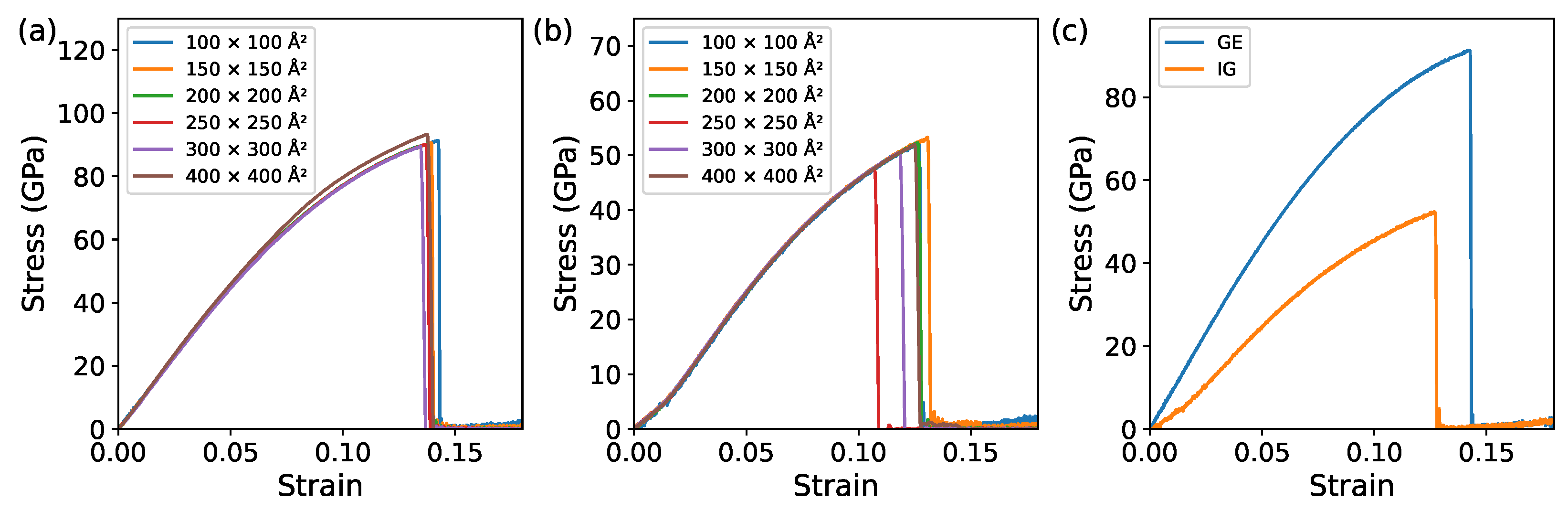
3.1.1. Monolayer Comparison of GE and IG

To study the mechanical properties of irida graphene, we compare the stress–strain relationships of irida graphene with graphene as well as their composite materials. Figure 2 shows monolayer graphene and monolayer irida tensile stress–strain curves of graphene at different atomic numbers. The number of atoms has little effect on the mechanical properties of monolayer graphene and irida graphene (Figure 2a,b). Further comparing graphene and irida graphene at the same atomic number, the fracture stress of the monolayer graphene structure is greater than that of monolayer irida graphene (as shown in Figure 2c), which indicates that the stretching of monolayer irida graphene is less strong than that of monolayer graphene.
Table 1 presents a comparative analysis of the mechanical properties of monolayer GE, IG, quasi-hexagonal-phase fullerene (qHPC 60 ), and quasi-tetragonal-phase fullerene (qTPC 60 ) [41]. Specifically, it compares fracture stress, strain energy, and Young’s modulus for these four materials. In terms of fracture stress, GE exhibits a significantly higher value at 90.1 GPa compared to the others. This discrepancy underscores the superior tensile strength of GE, implying its enhanced resistance to mechanical failure. This is likely attributed to the near-perfect atomic arrangement in GE, which minimizes structural defects and impurities, resulting in greater structural integrity. The data on strain energy also corroborate the enhanced mechanical performance of GE, with a value of 7.6 J/m 3 compared to IG’s 3.7 J/m 3 , qTPC 60 ’s 1.1 J/m 3 , and qHPC 60 ’s 1.6 J/m 3 . Strain energy signifies the material’s ability to absorb energy during deformation, and the higher value for GE indicates its capacity to absorb more energy during mechanical loading, further affirming its superior strength. Moreover, the Young’s modulus for GE is notably higher at 911.2 GPa compared to IG’s 520.4 GPa, qTPC 60 ’s 141.5 GPa, and qHPC 60 ’s 196.2 GPa. The elevated Young’s modulus of GE indicates its greater stiffness and resistance to deformation under stress, which is a valuable characteristic for various applications.

3.1.2. Bilayer Comparison of GE/GE, IG/IG, and GE/IG

Figure 3 shows the tensile stress–strain curves of doubl-layer graphene layer, graphene and irida graphene, and double-layer irida graphene under different numbers of atoms. Figure 3a is double-layer graphene; we can see that the double-layer graphene has obvious beating when stretching. This is because, when the double-layer graphene is stretched, the double-layer graphene breaks, not at the same time, but one layer at a time. Graphene breaks layer by layer. This is because the structure of double-layer graphene is formed by stacking monolayers of graphene layer by layer. Each layer has a certain elastic modulus and strength. When the stress reaches a certain level, the elastic modulus and strength of the first layer will be exhausted, causing plastic deformation of the first layer. As the stress increases, the elastic modulus and strength of the second layer will also be exhausted; this causes the second layer to plastically deform until the entire material breaks. Figure 3c is a model stacked by a layer of graphene and a layer of irida graphene. It can be seen from the figure that the stress–strain curve has obvious double peaks. Figure 3c is a model stacked by a layer of graphene and a layer of irida graphene. From the figure, the stress–strain curve has obvious double peaks. Figure 3b is irida graphene; it can be seen from the picture that the bilayer irida graphene breaks at the same time, and its fracture stress is relatively small. Even the maximum fracture stress of double-layer irida graphene does not exceed 60 GPa. A comparison of Figure 3a–c shows that change in the number of atoms has little effect on the fracture tensile stress of the three structures. Under the same number of atoms, the fracture stress of the bilayer graphene structure is the largest and the bilayer irida graphene is the smallest. According to Figure 3d, the stress–strain curve has obvious double peaks and the graphene layer is smaller than the irida graphene layer. It is less likely to be broken, which means that, during the stretching process, the irida graphene layer is broken first and the graphite layer is broken later. Therefore, this stacking model can enhance the tensile strength of irida graphene. Based on the findings from Figure 4, the fracture stress and strain variations of different structures stabilize when the box size reaches 200 × 200 Å2. In the subsequent simulation calculations, we have adopted this box size uniformly.
Table 2 offers a comprehensive examination of the mechanical properties of bilayer graphene (GE), bilayer irida graphene (IG), and the combination of one layer of graphene and one layer of iridium graphene structure (GE/IG). Starting with fracture stress, bilayer GE exhibits a substantial value of 91.5 GPa, indicative of its remarkable tensile strength. Conversely, bilayer IG displays a lower fracture stress of 51.4 GPa, suggesting a comparatively lower resistance to mechanical failure. Notably, the GE/IG structure presents an intriguing intermediate scenario, with fracture stresses of 67.3 GPa for the GE component and 48.5 GPa for the IG. This observation underscores the intricate interplay of mechanical properties in composite structures, potentially influenced by factors such as interface interactions and structural heterogeneity. Turning to strain energy, bilayer GE demonstrates a superior capacity to absorb energy during deformation, as indicated by its higher value of 7.8 J/m 3 . In contrast, bilayer IG exhibits a lower strain energy value of 3.4 J/m 3 , suggesting a reduced ability to withstand deformation-induced energy absorption. The GE/IG structure presents an intermediate strain energy value of 5.9 J/m 3 , reflecting the combined influence of GE and IG constituents on energy dissipation during mechanical loading. Lastly, the assessment of Young’s modulus reveals distinct stiffness characteristics among the three structures. Bilayer GE possesses a substantial Young’s modulus of 932.3 GPa, highlighting its rigidity. Bilayer IG, in contrast, displays a lower Young’s modulus of 543.5 GPa, indicating a comparatively higher susceptibility to deformation. The GE/IG structure showcases a Young’s modulus of 791.8 GPa, positioning it between the stiffness levels of pure GE and IG.
Comparing previous studies on bilayer graphene [42], it was found that when the number of atoms is the same in a monolayer, the fracture stress of bilayer graphene is less than that of monolayer graphene. The same situation exists when comparing monolayer irida graphene with bilayer irida graphene. This is due to the following: (1) Monolayer graphene is composed of a layer of carbon atoms and has a high degree of freedom and a thin film. Due to its flexibility, when stretched by external forces, it can better adapt to strain, thereby generating greater stress; (2) The elastic modulus of monolayer graphene is higher, which means that it is more sensitive to changes in strain. When stretched by an external force, monolayer graphene can quickly generate corresponding stress, which increases the relatively small atomic distance and forms strain; (3) Bilayer graphene is composed of two layers of carbon atoms stacked together. There is van der Waals interaction between the two layers. This interaction can offset part of the external force, thereby reducing the magnitude of its stress and strain.

3.2. Cracks Analysis with Different Sizes

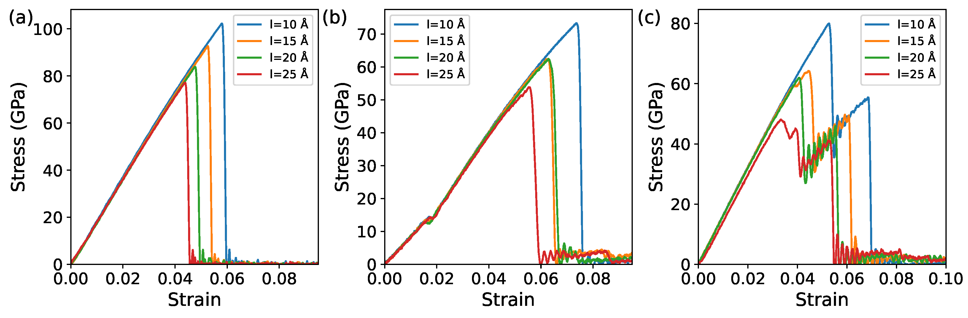
3.2.1. Monolayer Comparison of GE and IG

To study the effect of crack propagation on irida graphene, we chose the crack direction to be perpendicular to the stretching direction (along the x-axis) (along the y-axis); the crack width is 5 Å and the lengths are 10 Å, 15 Å, 20 Å, and 25 Å. The schematic diagram is shown in Figure 1c, and Figure 5 is the stress–strain curve of monolayer graphene (Figure 5a) and irida graphene (Figure 5b) under different crack lengths. The trends of the two curves are basically the same. It is the same as the effect of cracks on bilayer structures: as the crack length continues to increase, the fracture stress and strain of the two structures also continue to decrease, indicating that the increase in crack length has a greater impact on their fracture stress. This will weaken their tensile strength. By comparing graphene without cracks and irida graphene, it was found that the maximum crack length, L = 25 Å, will reduce their fracture stress by approximately three times. It shows that the occurrence of cracks has a great impact on the mechanical properties of the material.

3.2.2. Bilayer Comparison of GE/GE, IG/IG, and GE/IG

Figure 6 depicts the stress–strain curves for bilayer graphene and bilayer irida graphene under various crack lengths. We have chosen a crack width of 5 Å and lengths of L = 10 Å, L = 15 Å, L = 20 Å, and L = 25 Å. The crack geometry is shown in Figure 1c. The crack propagates along the y-axis (i.e., the crack is oriented at 90° to the tensile direction). As observed in Figure 6a, with an increase in crack length, the fracture stress and strain of bilayer graphene continue to decrease, indicating a reduction in its tensile strength as the crack length increases. Since the tensile direction is perpendicular to the crack growth direction, the ultimate fracture location remains perpendicular to the tensile direction. As the crack grows, the tensile strength continues to weaken, and the crack induces stress concentration within the graphene, diminishing its resistance to tensile deformation. Similar trends are observed in the stress–strain curves for bilayer irida graphene, as shown in Figure 6b, with its tensile strength decreasing with increasing crack length. However, the fracture behavior of graphene and irida graphene structures (as seen in Figure 6b) exhibits bimodal characteristics. As before, due to the presence of the crack, the relaxed structure exhibits a noticeable protrusion at the crack location. During the tensile process, the model first straightens the crack before breaking. Therefore, a preceding flat segment appears in the stress–strain curve, leading to the observed bimodal behavior. As seen in Figure 7, bilayer irida graphene, bilayer graphene, graphene, and irida graphene structures exhibit fracture strains of 0.046, 0.048, 0.105, and 0.135, respectively, with corresponding fracture stresses of 0.051, 0.049, 0.105, and 0.135. These results indicate that bilayer irida graphene is more prone to early fracture, while graphene structures exhibit the highest fracture strain, suggesting that graphene can delay the fracture of irida graphene materials. This suggests that graphene enhances the mechanical stability of irida graphene and improves its tensile strength.

3.3. Cracks Analysis with Different Crack Directions

To analyze the impact of different angles between cracks and the tensile direction on the mechanical properties of monolayer irida graphene, we selected cracks with angles of 0 ,   15 ,   30 , 45 ,   60 ,   75 , and 90 , and a crack length (L) of 25 Å as the research model; part of the crack shape is shown in Figure 1c. Figure 8 shows the stress–strain curves of cracks at different angles to the tensile direction, where (a) represents monolayer graphene, (b) represents monolayer irida graphene, (c) represents bilayer graphene, and (d) represents bilayer irida graphene. It can be observed from the figure that with the increase of the angle, both the fracture strain and the stress gradually decrease. Through the above research, it was found that bilayer graphene and bilayer irida graphene are more likely to break when perpendicular to the tensile direction.
Figure 9 shows the stress–strain curves of GE/IG with 0 , 15 , and 30 . Due to the presence of a bimodal structure, we selected three specific angles for comparison to enhance clarity, keeping the other two bilayer angles consistent. As the angle increases, the maximum fracture stress steadily decreases (as also observed in Figure 10a), but the fracture strain does not decrease significantly (which can be more intuitively seen in Figure 10b). This is because the fracture occurs layer by layer, requiring a longer time compared to the other two materials. Additionally, we found that, at larger angles, the time required for fracture increases, indicating that graphene and iridium graphene materials are more prone to fracture at larger angles, but the fracture process takes more time.
It is also found that the larger the angle, the smaller the influence, indicating that cracks perpendicular to the tensile direction have a greater impact on the material’s tensile strength. This can also be seen in Figure 10a, where it is also observed that smaller angles enhance the tensile capability of the material. The fracture strain is larger at smaller angles, indicating that the material is less likely to fracture at smaller crack angles (as shown in Figure 10b). The fracture strain of the GE/IG structure fluctuates with the crack angle, and the fracture strain changes with the angle. It first decreases and then increases, and the fracture strain is larger than other structures, indicating that the fracture time increases, proving that graphene as a substrate can make irida graphene more stable. It is also observed that smaller angles enhance the material’s tensile capability. In conclusion, the angle between cracks and the tensile direction can affect the material’s tensile strength. Larger angles make the material more prone to fracture; therefore, it is important to pay attention to the angle between cracks and the tensile direction in practical applications. Minimizing cracks in the material and avoiding cracks appearing in positions perpendicular to the tensile direction is advisable.
The change trends of the three structures are basically the same, indicating that the cracks are more consistent with the tensile direction. The less likely the material is to break, the greater the angle between the crack and the tensile direction of the material, and the reason for its lower tensile strength is the weakening of the dispersion effect. There are tiny flaws or cracks in the material that, when tension is applied, expand and gradually cause the material to break. If the angle between the crack and the tensile direction is small, the tensile force will be concentrated on the crack, causing the crack to grow faster. When the angle between the crack and the tensile direction is large, the tensile force is dispersed into the material around the crack, and the energy used to resist crack expansion also increases, making the tensile strength of the material relatively large. Therefore, the greater the angle between the crack and the tensile direction, the smaller the tensile strength. At the same time, we also found that as the included angle increases, the effect of the angle on the fracture stress remains basically unchanged. Therefore, in actual use, excessively large included angles should be avoided to prevent the material from being easily broken.

4. Conclusions

We used molecular dynamics simulation to compare the effects of cracks and atomic number on the tensile properties of bilayer irida graphene. We analyzed the influence of atomic number, crack length, and the angle between the crack and the stretching direction on the fracture stress. The results showed that the effect of atomic number on irida graphene was relatively small, but the effect of cracks was significant. The longer the crack length, the lower the fracture stress, and the larger the angle between the crack and the stretching direction, the lower the fracture stress. The bilayer graphene fracture occurred layer by layer, while irida graphene fracture occurred simultaneously. In addition, it was found that the fracture stress of monolayer irida graphene was greater than that of bilayer irida graphene. The tensile resistance of irida graphene was less than that of graphene, and the bilayer structure of graphene could enhance the tensile resistance of irida graphene as a substrate. The results of this study provide valuable insights into the potential applications of bilayer irida graphene in advanced nanoscale electronic devices and hydrogen storage. However, in practical applications, factors such as temperature, pressure, and strain rate will also be considered, as mechanical properties are only one aspect of a material. The study of thermal properties is also important for a material. Therefore, a comprehensive study of its thermal properties is necessary. Overall, the results of this study are meaningful for the design and use of irida graphene-based devices and emphasize the importance of considering the length of irida graphene cracks and the angle between the cracks and the stretching direction.

Author Contributions

Conceptualization, Q.P. and H.-K.T.; methodology, T.Y. and Q.P.; software, T.Y. and Q.P.; validation, J.L., S.Z., T.L. and T.Y.; formal analysis, J.L., M.H., T.Y. and H.-K.T.; investigation, S.Z., T.L. and H.-K.T.; resources, Y.Z. and H.-K.T.; data curation, T.Y. and H.-K.T.; writing—original draft preparation, J.L., M.H. and T.Y.; writing—review and editing, J.L., T.Y., Q.P. and H.-K.T.; visualization, J.L., M.H. and H.-K.T.; supervision, Q.P. and H.-K.T.; project administration, T.Y. and Q.P.; funding acquisition, Y.Z., Q.P. and H.-K.T. All authors have read and agreed to the published version of the manuscript.

Funding

This research was funded by the Start-Up Research Fund in HITSZ (Grant No. ZX20210478, Grant No. X20220001), the Young Scientists Fund of the National Natural Science Foundation of China (Grant No. 12204130), and Shenzhen Key Laboratory of Advanced Functional Carbon Materials Research and Comprehensive Application (Grant No. ZDSYS20220527171407017). Q. P. would like to acknowledge the support provided by the Shenzhen Science and Technology Program (Grant No. KQTD20200820113045081), the National Natural Science Foundation of China (Grant No. 12272378), and the High-level Innovation Research Institute Program of Guangdong Province (No. 2020B0909010003).

Data Availability Statement

The data presented in this study are available on request.

Conflicts of Interest

The authors declare no conflict of interest.

References

  1. Novoselov, K.S.; Geim, A.K.; Morozov, S.V.; Jiang, D.; Zhang, Y.; Dubonos, S.V.; Grigorieva, I.V.; Firsov, A.A. Electric field effect in atomically thin carbon films. Science 2004, 306, 666–669. [Google Scholar] [CrossRef] [PubMed]
  2. Aliofkhazraei, M.; Ali, N.; Milne, W.I.; Ozkan, C.S.; Mitura, S.; Gervasoni, J.L. Mechanical properties of graphene. In Graphene Science Handbook; CRC Press: Boca Raton, FL, USA, 2016; pp. 19–32. [Google Scholar] [CrossRef]
  3. Agius Anastasi, A.; Konstantinos Ritos, G.C.; Borg, M.K. Mechanical properties of pristine and nanoporous graphene. Mol. Simul. 2016, 42, 1502–1511. [Google Scholar] [CrossRef]
  4. Dewapriya, M.A.N.; Srikantha Phani, A.; Rajapakse, R.K.N. Influence of temperature and free edges on the mechanical properties of graphene. Model. Simul. Mater. Sci. Eng. 2013, 21, 065017. [Google Scholar] [CrossRef]
  5. Zandiatashbar, A.; Lee, G.H.; An, S.J.; Lee, S.; Mathew, N.; Terrones, M.; Hayashi, T.; Picu, C.R.; Hone, J.; Koratkar, N. Effect of defects on the intrinsic strength and stiffness of graphene. Nat. Commun. 2014, 5, 3186. [Google Scholar] [CrossRef]
  6. Cheng, Y.; Zhou, S.; Hu, P.; Zhao, G.; Li, Y.; Zhang, X.; Han, W. Enhanced mechanical, thermal, and electric properties of graphene aerogels via supercritical ethanol drying and high-temperature thermal reduction. Sci. Rep. 2017, 7, 1439. [Google Scholar] [CrossRef] [PubMed]
  7. Ranjbartoreh, A.R.; Wang, B.; Shen, X.; Wang, G. Advanced mechanical properties of graphene paper. J. Appl. Phys. 2011, 109, 014306. [Google Scholar] [CrossRef]
  8. Li, X.; Guo, J. Numerical Investigation of the Fracture Properties of Pre-Cracked Monocrystalline/Polycrystalline Graphene Sheets. Materials 2019, 12, 263. [Google Scholar] [CrossRef]
  9. Akinwande, D.; Brennan, C.J.; Scott Bunch, J.; Egberts, P.; Felts, J.R.; Gao, H.; Huang, R.; Kim, J.S.; Li, T.; Li, Y.; et al. A review on mechanics and mechanical properties of 2D materials—Graphene and beyond. Extrem. Mech. Lett. 2017, 13, 42–77. [Google Scholar] [CrossRef]
  10. Cao, Q.; Geng, X.; Wang, H.; Wang, P.; Liu, A.; Lan, Y.; Peng, Q. A Review of Current Development of Graphene Mechanics. Crystals 2018, 8, 357. [Google Scholar] [CrossRef]
  11. Lee, G.H.; Cooper, R.C.; An, S.J.; Lee, S.; van der Zande, A.; Petrone, N.; Hammerberg, A.G.; Lee, C.; Crawford, B.; Oliver, W.; et al. High-strength chemical-vapor-deposited graphene and grain boundaries. Science 2013, 340, 1073–1076. [Google Scholar] [CrossRef]
  12. Neto, A.H.C.; Castro Neto, A.H.; Guinea, F.; Peres, N.M.R.; Novoselov, K.S.; Geim, A.K. The electronic properties of graphene. Rev. Mod. Phys. 2009, 81, 109. [Google Scholar] [CrossRef]
  13. Balandin, A.A.; Ghosh, S.; Bao, W.; Calizo, I.; Teweldebrhan, D.; Miao, F.; Lau, C.N. Superior thermal conductivity of single-layer graphene. Nano Lett. 2008, 8, 902–907. [Google Scholar] [CrossRef]
  14. Zhao, Q.; Nardelli, M.B.; Bernholc, J. Ultimate strength of carbon nanotubes: A theoretical study. Phys. Rev. B 2002, 65, 144105. [Google Scholar] [CrossRef]
  15. Pereira Júnior, M.L.; da Cunha, W.F.; Giozza, W.F.; de Sousa Junior, R.T.; Ribeiro Junior, L.A. Irida-graphene: A new 2D carbon allotrope. FlatChem 2023, 37, 100469. [Google Scholar] [CrossRef]
  16. Allen, M.J.; Tung, V.C.; Kaner, R.B. Honeycomb carbon: A review of graphene. Chem. Rev. 2010, 110, 132–145. [Google Scholar] [CrossRef] [PubMed]
  17. Deng, B.; Hou, J.; Zhu, H.; Liu, S.; Liu, E.; Shi, Y.; Peng, Q. The normal-auxeticity mechanical phase transition in graphene. 2D Mater. 2017, 4, 021020. [Google Scholar] [CrossRef]
  18. Peng, Q.; Liang, C.; Ji, W.; De, S. A theoretical analysis of the effect of the hydrogenation of graphene to graphane on its mechanical properties. Phys. Chem. Chem. Phys. 2013, 15, 2003–2011. [Google Scholar] [CrossRef] [PubMed]
  19. Tozzini, V.; Pellegrini, V. Prospects for hydrogen storage in graphene. Phys. Chem. Chem. Phys. 2013, 15, 80–89. [Google Scholar] [CrossRef]
  20. Tan, Y.; Tao, X.; Ouyang, Y.; Peng, Q. Stable and 7.7 wt% hydrogen storage capacity of Ti decorated Irida-Graphene from first-principles calculations. Int. J. Hydrogen Energy 2023, in press. [Google Scholar] [CrossRef]
  21. Zhang, Y.F.; Guo, J. Li-decorated 2D Irida-graphene as a potential hydrogen storage material: A dispersion-corrected density functional theory calculations. Int. J. Hydrogen Energy 2023, in press. [Google Scholar] [CrossRef]
  22. Papageorgiou, D.G.; Kinloch, I.A.; Young, R.J. Mechanical properties of graphene and graphene-based nanocomposites. Prog. Mater. Sci. 2017, 90, 75–127. [Google Scholar] [CrossRef]
  23. Lee, C.; Wei, X.; Kysar, J.W.; Hone, J. Measurement of the elastic properties and intrinsic strength of monolayer graphene. Science 2008, 321, 385–388. [Google Scholar] [CrossRef] [PubMed]
  24. Roy, S.; Zhang, X.; Puthirath, A.B.; Meiyazhagan, A.; Bhattacharyya, S.; Rahman, M.M.; Babu, G.; Susarla, S.; Saju, S.K.; Tran, M.K.; et al. Structure, properties and applications of two-dimensional hexagonal boron nitride. Adv. Mater. 2021, 33, e2101589. [Google Scholar] [CrossRef] [PubMed]
  25. Imani Yengejeh, S.; Liu, J.; Kazemi, S.A.; Wen, W.; Wang, Y. Effect of structural phases on mechanical properties of molybdenum disulfide. ACS Omega 2020, 5, 5994–6002. [Google Scholar] [CrossRef]
  26. Sha, Z.D.; Pei, Q.X.; Ding, Z.; Jiang, J.W.; Zhang, Y.W. Mechanical properties and fracture behavior of single-layer phosphorene at finite temperatures. J. Phys. D Appl. Phys. 2015, 48, 395303. [Google Scholar] [CrossRef]
  27. Sun, Y.; Peng, Q.; Lu, G. Quantum mechanical modeling of hydrogen assisted cracking in aluminum. Phys. Rev. B Condens. Matter 2013, 88, 104109. [Google Scholar] [CrossRef]
  28. Zhu, H.; Fan, T.; Peng, Q.; Zhang, D. Giant Thermal Expansion in 2D and 3D Cellular Materials. Adv. Mater. 2018, 30, e1705048. [Google Scholar] [CrossRef]
  29. Peng, Q.; Ji, W.; De, S. Mechanical properties of the hexagonal boron nitride monolayer: Ab initio study. Comput. Mater. Sci. 2012, 56, 11–17. [Google Scholar] [CrossRef]
  30. Peng, Q.; Lu, G. A comparative study of fracture in Al: Quantum mechanical vs. empirical atomistic description. J. Mech. Phys. Solids 2011, 59, 775–786. [Google Scholar] [CrossRef]
  31. Peng, Q.; Zhang, X.; Hung, L.; Carter, E.A.; Lu, G. Quantum simulation of materials at micron scales and beyond. Phys. Rev. B Condens. Matter 2008, 78, 054118. [Google Scholar] [CrossRef]
  32. Hou, J.; Deng, B.; Zhu, H.; Lan, Y.; Shi, Y.; De, S.; Liu, L.; Chakraborty, P.; Gao, F.; Peng, Q. Magic auxeticity angle of graphene. Carbon 2019, 149, 350–354. [Google Scholar] [CrossRef]
  33. Peng, Q.; Meng, F.; Yang, Y.; Lu, C.; Deng, H.; Wang, L.; De, S.; Gao, F. Shockwave generates dislocation loops in bcc iron. Nat. Commun. 2018, 9, 4880. [Google Scholar] [CrossRef] [PubMed]
  34. Plimpton, S. Fast parallel algorithms for short-range molecular dynamics. J. Comput. Phys. 1995, 117, 1–19. [Google Scholar] [CrossRef]
  35. Stukowski, A. Visualization and analysis of atomistic simulation data with OVITO–the Open Visualization Tool. Model. Simul. Mater. Sci. Eng. 2009, 18, 015012. [Google Scholar] [CrossRef]
  36. Humphrey, W.; Dalke, A.; Schulten, K. VMD: Visual molecular dynamics. J. Mol. Graph. 1996, 14, 33–38. [Google Scholar] [CrossRef]
  37. Stuart, S.J.; Tutein, A.B.; Harrison, J.A. A reactive potential for hydrocarbons with intermolecular interactions. J. Chem. Phys. 2000, 112, 6472–6486. [Google Scholar] [CrossRef]
  38. Yang, X.; Wu, S.; Xu, J.; Cao, B.; To, A.C. Spurious heat conduction behavior of finite-size graphene nanoribbon under extreme uniaxial strain caused by the AIREBO potential. Phys. E Low Dimens. Syst. Nanostruct. 2018, 96, 46–53. [Google Scholar] [CrossRef]
  39. Wang, X.; Hong, Y.; Ma, D.; Zhang, J. Molecular dynamics study of thermal transport in a nitrogenated holey graphene bilayer. J. Mater. Chem. C Mater. Opt. Electron. Devices 2017, 5, 5119–5127. [Google Scholar] [CrossRef]
  40. Her, S.C.; Zhang, K.C. Mode I fracture toughness of graphene reinforced nanocomposite film on Al substrate. Nanomaterials 2021, 11, 1743. [Google Scholar] [CrossRef]
  41. Yu, T.; Li, J.; Han, M.; Zhang, Y.; Li, H.; Peng, Q.; Tang, H.K. Enhancing the Mechanical Stability of 2D Fullerene with a Graphene Substrate and Encapsulation. Nanomaterials 2023, 13, 1936. [Google Scholar] [CrossRef]
  42. Yu, T.; Li, J.; Yang, Z.; Li, H.; Peng, Q.; Tang, H.K. Effects of Crack Formation on the Mechanical Properties of Bilayer Graphene: A Comparative Analysis. Crystals 2023, 13, 584. [Google Scholar] [CrossRef]
Figure 1. Schematic diagram of (a) the atomic structure of irida graphene, (b) bilayer irida graphene structure and (c) cracks, with angles of 0°, 45°, and 90° to the tensile direction. The distance between layers is calculated using their relative coordinates.
Jcs 07 00490 g001
Figure 2. Tensile stress–strain curves under different numbers of atoms: (a) monolayer graphene (GE), (b) monolayer irida graphene (IG), (c) comparison of stress–strain curves of two structures with box size of 200 × 200 Å2.
Jcs 07 00490 g002
Figure 3. Tensile stress–strain curves under different atoms: (a) double-layer graphene (GE/GE), (b) double-layer irida graphene (IG/IG), (c) the combination of one layer of graphene and one layer of iridium graphene structure (GE/IG), (d) comparison of stress–strain curves of three structures with box size of 200 × 200 Å2.
Jcs 07 00490 g003
Figure 4. Fracture stress and strain at different box size: (a) relationship between fracture stress and box size, (b) relationship between fracture strain and box size.
Jcs 07 00490 g004
Figure 5. Tensile stress–strain curves under different numbers of atoms: (a) monolayer graphene (GE), (b) monolayer irida graphene (IG).
Jcs 07 00490 g005
Figure 6. Tensile stress–strain curves of cracks of different lengths when the crack is 90° to the x-axis: (a) bilayer graphene (GE/GE), (b) double-layer irida graphene (IG/IG), (c) the composite structure formed by combining GE and IG (GE/IG).
Jcs 07 00490 g006
Figure 7. Fracture process of (a) GE/GE, (b) IG/IG, and (c) GE/IG.
Jcs 07 00490 g007
Figure 8. Tensile stress–strain curves under different angles of cracks: (a) monolayer graphene, (b) monolayer irida graphene, (c) bilayer graphene, (d) bilayer irida graphene.
Jcs 07 00490 g008
Figure 9. Tensile stress–strain curves under different angles of cracks for the composite structure formed by combining GE and IG (GE/IG).
Jcs 07 00490 g009
Figure 10. Fracture stress and strain at different crack angles: (a) relationship between fracture stress and crack angle, (b) relationship between fracture strain and crack angle.
Jcs 07 00490 g010
Table 1. Comparison of the fracture stress, strain energy, and Young’s modulus for monolayer GE, IG, qTPC 60 , and qHPC 60 structures.
StrctureFracture Stress (GPa)Strain Energy (J/m 3 )Young’s Modulus (GPa)
GE90.17.6911.2
IG52.33.7520.4
qTPC 60 17.61.1134.7
qHPC 60 24.51.6191.6
Table 2. Comparison of the fracture stress, strain energy, and Young’s modulus for GE/GE, IG/IG, and GE/IG structures.
StrctureFracture Stress (GPa)Strain Energy (J/m 3 )Young’s Modulus (GPa)
GE/GE91.57.8932.3
IG/IG51.43.4543.5
GE/IG67.3/48.55.9791.8
Disclaimer/Publisher’s Note: The statements, opinions and data contained in all publications are solely those of the individual author(s) and contributor(s) and not of MDPI and/or the editor(s). MDPI and/or the editor(s) disclaim responsibility for any injury to people or property resulting from any ideas, methods, instructions or products referred to in the content.

