Article

Transferability of the Structure–Property Relationships from Laser-Pretreated Metal–Polymer Joints to Aluminum–CFRP Hybrid Joints

1
German Aerospace Center (DLR; Deutsches Zentrum für Luft- und Raumfahrt e.V.), Institute of Materials Research, Linder Höhe, 51147 Cologne, Germany
2
Chair of Materials Test Engineering (WPT), TU Dortmund University, Baroper Str. 303, 44227 Dortmund, Germany
3
Institute for Lightweight Design with Hybrid Systems, Automotive Lightweight Design (LiA), Paderborn University, Mersinweg 7, 33100 Paderborn, Germany
*
Author to whom correspondence should be addressed.
J. Compos. Sci. 2023, 7(10), 427; https://doi.org/10.3390/jcs7100427
Submission received: 13 September 2023 / Revised: 29 September 2023 / Accepted: 10 October 2023 / Published: 12 October 2023
(This article belongs to the Special Issue Polymer Composites and Fibers, Volume II)

Abstract

:
The transferability of structure–property relationships for laser-pretreated metal adhesive joints to laser-pretreated metal–carbon-fiber-reinforced plastic (CFRP) bonds was investigated. Single-lap shear tests were performed on hybrid AW 6082-T6–CFRP specimens pretreated with the same pulsed laser surface parameter sets on the metal surface as previously tested, AW 6082-T6–E320 metal adhesive joints. The fracture surfaces were characterized to determine the type of failure and elucidate differences and commonalities in the link between surface structures and single-lap shear strengths. Digital image analyses of the hybrid specimens’ fractured surfaces were used to quantify remaining CFRP fragments on the metallic joint side. The results indicate that high surface enlargements and the presence of undercut structures lead to single-lap shear strengths exceeding 40 MPa and 35 MPa for unaged and aged hybrid specimens, respectively. Whereas for the metal–polymer joints, the trend from high strength to weakly bonded specimens is largely continuous with the degree of surface structuring, hybrid metal–CFRP joints exhibit a drastic drop in joint performance after aging if the laser-generated surface structures are less pronounced with low surface enlargements and crater depths. Surface features and hydrothermal aging determine whether the specimens fail cohesively or adhesively.

1. Introduction

The development of new lightweight solutions for structural parts of future vehicles helps to enable the widespread use of electric powertrain concepts and increases the effectiveness of fuel-based solutions. One promising strategy for lightweight construction is the replacement of metal parts by hybrid structures consisting of metallic and fiber-reinforced plastic components. This multi-material approach combines the high strength and ductility of the metal with the low density, high strength, and stiffness of the fiber-reinforced composite material. The joint interface between the metal and polymer component is, however, susceptible to failure caused by surface contaminations like oils [1], which can lead to weakening of the bonding. A pulsed laser surface pretreatment of the fiber-reinforced plastic [2,3] and the metal, or the metal alone [4,5,6,7], prior to adhesion, has proven to be an effective and reproducible method to counter this problem and increase the mechanical strength of the hybrid joint. In contrast to pretreatments of metal and metal oxide surfaces prior to adhesion from the automotive and aerospace industry like grit blasting [8] or acid anodization [9,10], the pulsed laser metal surface pretreatment offers a high reproducibility and does not generate chemical waste. However, the findings of Schanz et al. also revealed that the pretreatment parameters have to be chosen carefully to promote enhanced mechanical strength and prevent a loss of mechanical strength by corrosion processes [11].
In prior studies on metal–polymer joints that were adhesively bonded after laser surface pretreatments, it was commonly assumed that besides the removal of surface contaminations, the surface enlargement and the morphology of the micro- and nanostructures generated by the laser were responsible for a further increase in mechanical strength and resistance against hydrothermal aging of the joints [12,13,14,15]. While several studies can be found that investigate the structure–property relationships of metal–polymer adhesive joints, further research is needed to reveal if the same relationships can be found in metal-fiber-reinforced plastic hybrid adhesive joints. Trauth et al. suggested that the surface enlargement also plays an important role in the enhancement in the interaction of the bonding partners in hybrid titanium–self-reinforced PLA joints [7]. Furthermore, Akman et al. found that laser-pretreated aluminum–CFRP hybrid joints with the deepest craters provided the highest single-lap shear (SLS) strengths [6]. Ostapiuk et al. concluded that the morphology of the surface micro- and nano-sized features also plays an important role for the resulting mechanical strength of anodized AW 2024-T3–CFRP or glass-fiber-reinforced plastic hybrids [16]. To provide further understanding of the influences of different surface structures on the mechanical strength of hybrid adhesive joints, a qualitative and quantitative assessment of the structures is necessary.
In a previous study, we characterized the laser-generated surface structures on an AW 6082-T6 specimen that were adhesively bonded with the epoxy adhesive E320. The laser-induced surface enlargement on the micro- and nanoscale, as well as the depth of the ablated craters on the surface, were determined through a digital image analysis approach for scanning electron microscope (SEM) images and a laser scanning microscope (LSM). It was concluded that surface structures leading to a high micro- and nano-surface enlargement, combined with deep melt craters and undercut structures, promote high SLS strengths and a high resistance against hydrothermal aging [17].
In order to investigate the influence of the surface morphology on the mechanical performance and aging resistance of AW 6082-T6–CFRP hybrid joints, the SLS strengths of hybrid specimens before and after 7 days of hydrothermal aging are determined. The AW 6082-T6 surfaces are pretreated with the same laser parameter sets that have been investigated in the previous study [17] so that the influence of the surface enlargement, crater depth, and undercut structures on the SLS strength of hybrid specimens can be directly compared with AW 6082-T6–E320 adhesive joints. Furthermore, stereomicroscopic and SEM analyses of the fracture surfaces are performed in order to investigate the influence of the laser-generated surface structures on the failure patterns of hybrid and adhesively bonded metal SLS specimens. These experiments allow similarities and differences to be revealed in the structure–property relationships of metal–polymer and hybrid metal–CFRP adhesive joints with the same polymer acting as an adhesive and matrix material. This enables the evaluation of the transferability of the findings from metal–polymer to hybrid metal-CFRP adhesive bonds.

2. Materials and Methods

2.1. Materials

Sheets of the aluminum alloy AW 6082-T6 measuring 150 × 150 × 2 mm3 provided by Ullner und Ullner GmbH (Paderborn, Germany) are pressed with CFRP to hybrid plates. The aluminum alloy contains the main alloying elements Mg and Si and is delivered in the T6 state [18].
The CFRP prepreg sheets consist of the epoxy resin E320 as the matrix material and a carbon fiber volume content of 39%. The molecular formula of the E320 thermoset polymer is C19H23ClO4 and the final reaction product is Poly-Bisphenol-A-Epichlorhydrine [19]. The CFRP is provided as unidirectional prepreg material by SGL Carbon Group (Wiesbaden, Germany).

2.2. Methods

2.2.1. Laser Metal Surface Pretreatment

The influence of different surface structures on the resulting SLS strength of hybrid AW 6082-T6–CFRP specimens is investigated. The AW 6082-T6 sheets are pretreated with a pulsed Nd:YAG CL20 laser (Clean Lasersysteme GmbH, Herzogenrath, Germany) on the surface of the aluminum alloy sheets that will later form the interface with the CFRP material. The laser produces a gaussian laser profile and operates with a wavelength of 1064 nm. The mean pulse length is 110 ns and the duty cycle for all pretreatments is set to 40%. Prior to the laser pretreatment and co-curing of the prepreg and the metal, the aluminum sheets are degreased with acetone.
The laser surface treatment was described in more detail in reference [17], where the same pulsed Nd: YAG laser was used for the pretreatment of AW 6082-T6 adherents prior to adhesive bonding and mechanical testing. Here, different laser parameter sets were used to create different surface micro- and nanostructures that influenced the mechanical strength of the adhesive joints. In a similar fashion, the parameters of laser power, frequency, laser spot overlap, and the number of subsequent scans of the same spot are varied in this study to create the same varying surface structures as in the previous case [17]. These parameter sets are ranked according to the performance of the specimens in the initial state and after seven days of hydrothermal aging in 80 °C deionized water. The parameter sets that lead to the three best, medium, and worst results in the SLS test are chosen as pretreatment parameter sets, which are referred to as (the parameter sets of) rank R1-3, R17-19, and R34-36, respectively (Table 1). The morphology of the resulting surface micro- and nanostructures is summarized in Table A1 in Appendix A.

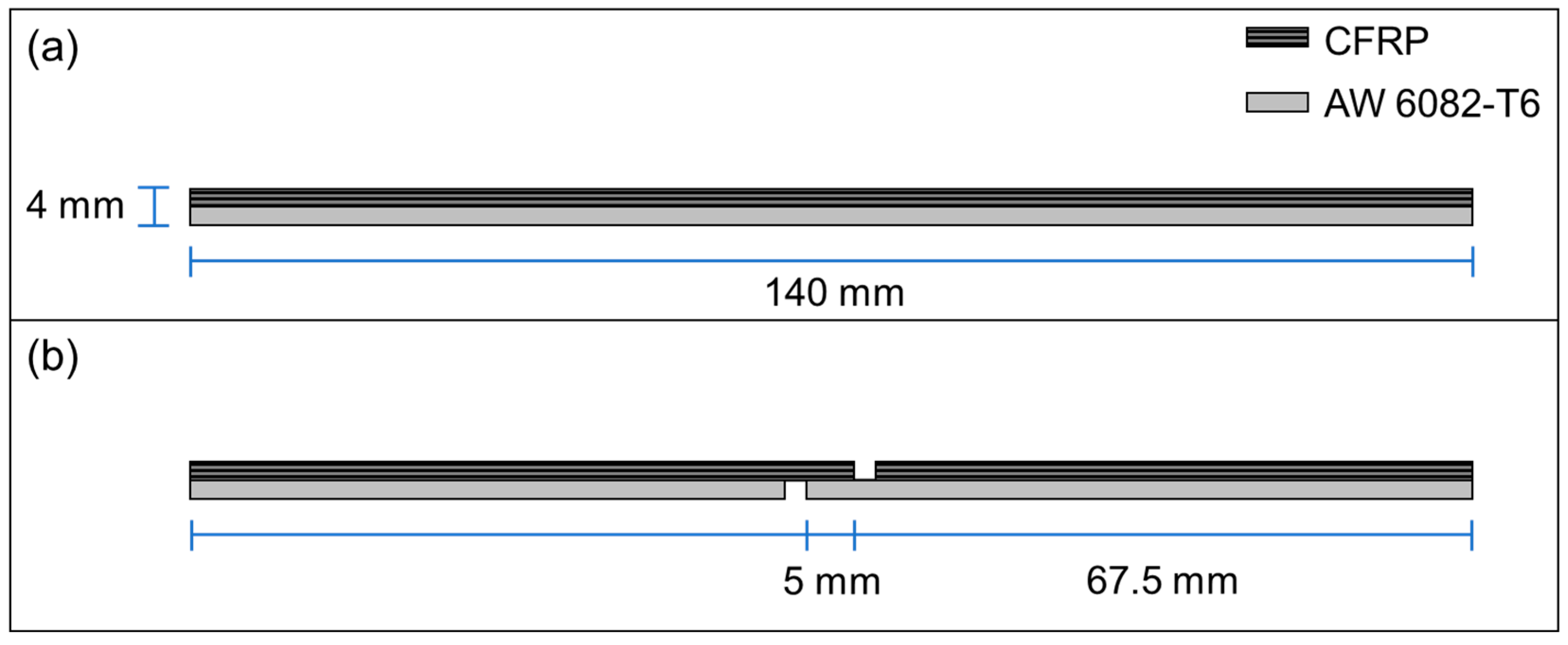
2.2.2. Production of the Single-Lap Shear (SLS) Specimens

Laser-pretreated, as well as degreased but not further pretreated, AW 6082-T6 sheets are pressed to hybrid plates with the CFRP prepreg material. To this end, on each aluminum sheet, eight layers of the prepreg material are placed with unidirectional fiber orientation so that a thickness of 2 mm is achieved for the CFRP component. The orientation of the fibers is chosen to be parallel to the rolling direction of the AW 6082-T6 sheets. The load in the SLS test is also applied parallel to the rolling, and therefore the fiber, direction. All hybrid sheets are then cured at 150 °C for 20 min with a pressure of 0.5 MPa in a LaboPress P200S hot press (VOGT Labormaschinen GmbH, Berlin, Germany). After the curing process, an additional post-curing step is performed at 180 °C for 300 min without pressure. In the previous work of Wu et al. [20], these curing parameters were found to be suitable for the production of the AW 6082-T6–CFRP laminates. However, a slight elastic deformation of the hybrid sheets and the final specimens occurred due to differences in thermal expansion of the materials and could not be entirely avoided.
After curing, specimens with the dimensions of 140 × 10 × 4 mm3 are water-jet-cut from the hybrid plates (Figure 1a). Notches are created on the metal and the CFRP sides using a circular saw (blade thickness of 2 mm) in order to create the final hybrid SLS specimens. These specimens then exhibit a joint or overlap area of 10 × 5 mm2 (Figure 1b), similar to the metal–polymer SLS samples in ref. [17]. Six specimens are produced with each laser parameter set as well as six additional untreated specimens.
Of each set of specimens, three specimens are hydrothermally aged in deionized water at 80 °C for seven days. The specimen dimensions are reduced, compared to the standard for SLS testing [21], in order to exclude plastic deformation of the metal adherents in the hybrid during SLS testing that would pose an additional influence on the resulting SLS strength. Due to differences in the thermal expansion coefficients of AW 6082-T6 and the CFRP, all hybrid specimens are slightly curved toward the AW 6082-T6 component.
The preparation and testing of the AW 6082-T6–E320 SLS specimens with the same laser pretreatment parameter sets as the hybrid specimens of this study are described in the previous study [17]. The results of the tests are displayed only for the comparison in Section 4.

2.2.3. Single-Lap Shear Tests of Hybrid Specimens

The single-lap shear tests of the hybrid AW 6082-T6–CFRP specimens are performed according to EN 1465 [21]. An Instron 5566A universal testing machine (Instron GmbH, Darmstadt, Germany) with a 10 kN load cell is used to test the specimens. All specimens are tested with a free specimen length of 40 mm and a load rate of 1 mm/min. The testing machine records the applied load and the machine displacement for each test.
Since there are slight variations in the overlap area due to the accuracy of the circular saw used to create the notches in the SLS specimens, the true joint area of each specimen is determined using a Keyence VHX-1000 stereomicroscope (Keyence Deutschland GmbH, Neu-Isenburg, Germany) by averaging the length and width of the bonded area of the two fracture surfaces. The SLS strength is then calculated by dividing the maximum force recorded in the SLS test by the true joint area. The same testing parameters and method for calculating the SLS strength was used in [17] for AW 6082-T6–E320 specimens.

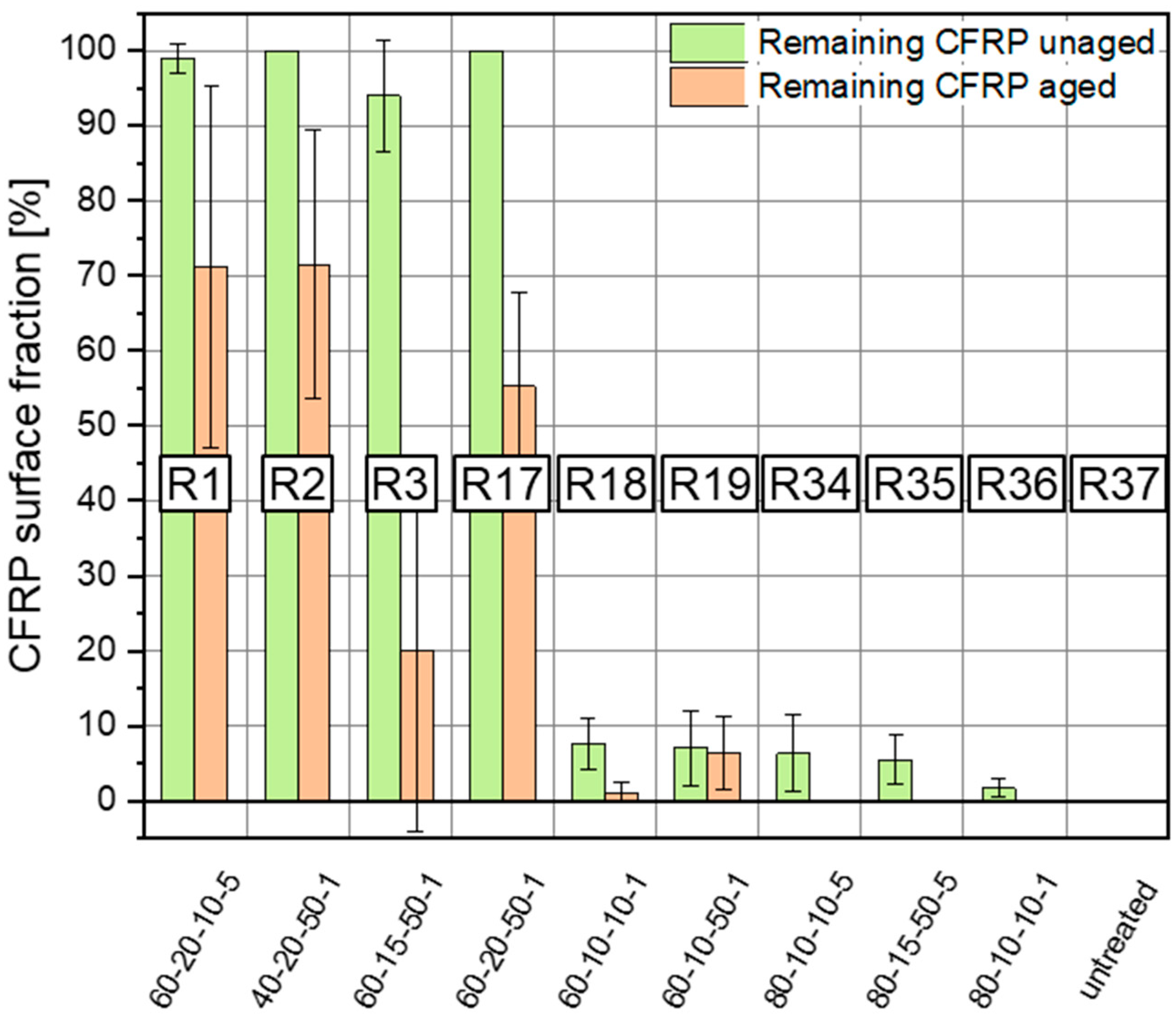
2.2.4. Quantification of Remaining CFRP Fragments on the Fracture Surfaces

Based on the images from the surfaces of failed SLS joints, the amount of remaining CFRP on the metal fracture surface is calculated using the software Fiji (ImageJ 1.54f) [22]. Initially, the image is converted into an 8-bit greyscale image and the area surrounding the fracture surface is removed. Then, the image is segmented such that the fracture surface is split into bright areas without the remaining CFRP and dark areas with CFRP (Figure 2). In the selected area of the fracture surface, the percentage of the surface fraction of dark areas is determined using the “analyze particles” function. On the metal surfaces, the fractions are measured and the arithmetic mean value for each specimen set is calculated.

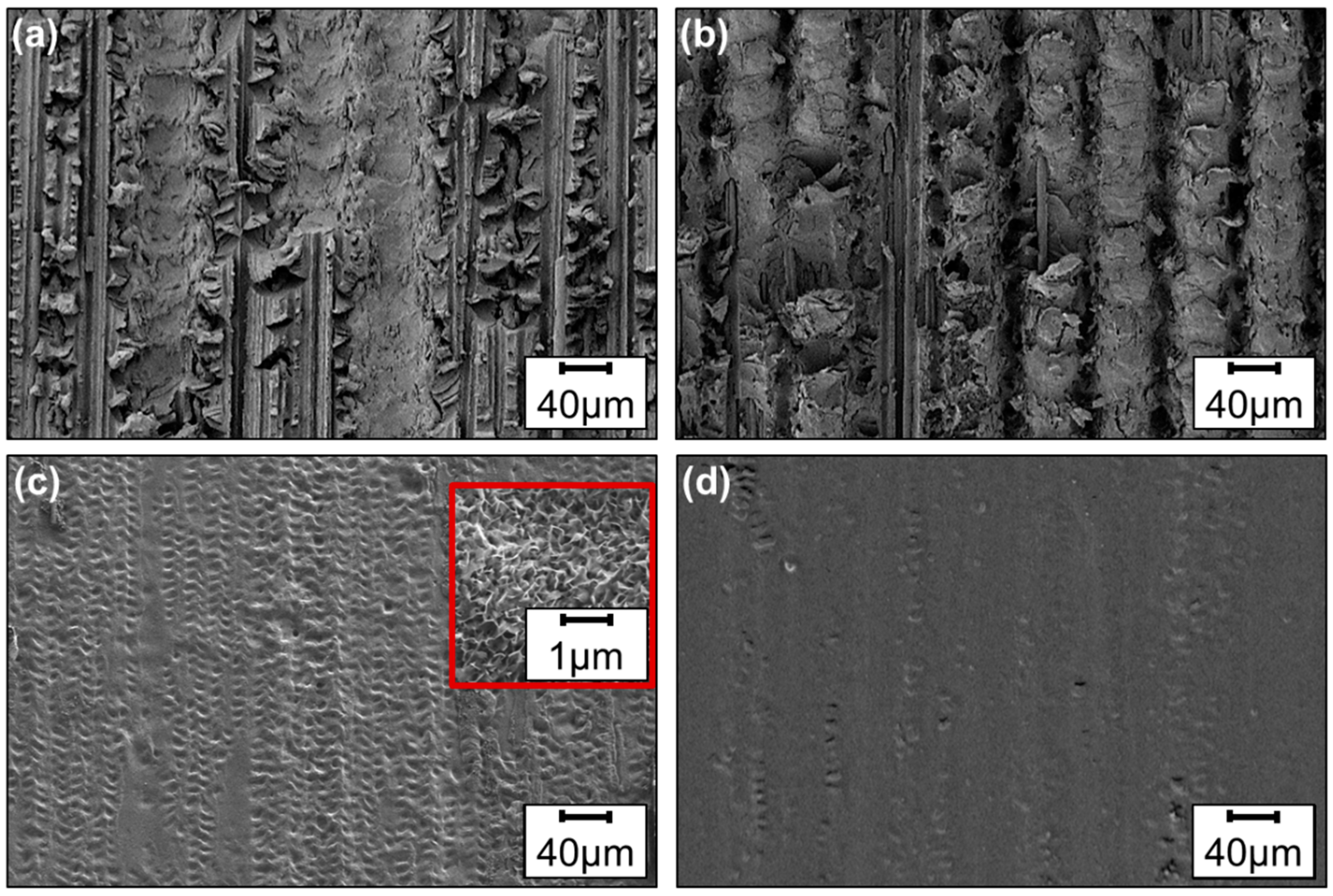
2.2.5. Scanning Electron Microscopy (SEM) Analysis of the Fracture Surfaces

In order to further evaluate the transferability of the structure–property relationships of laser-pretreated metal adhesive bonds to hybrid specimens, the fracture surfaces of hybrid SLS specimens, as well as adhesively bonded AW 6082-T6–E320 SLS specimens with the same laser metal surface pretreatment that have been tested in prior studies [17], are analyzed in this study. The analysis of the fracture surfaces of the SLS specimens is performed using an Ultra 55 scanning electron microscope (SEM) from Carl Zeiss Microscopy GmbH (Jena, Germany). All images are acquired with the SE2 secondary electron detector of the device with an aperture of 30 µm. The acceleration voltage is set to 2 kV and the working distance to 8.5 mm.

3. Results

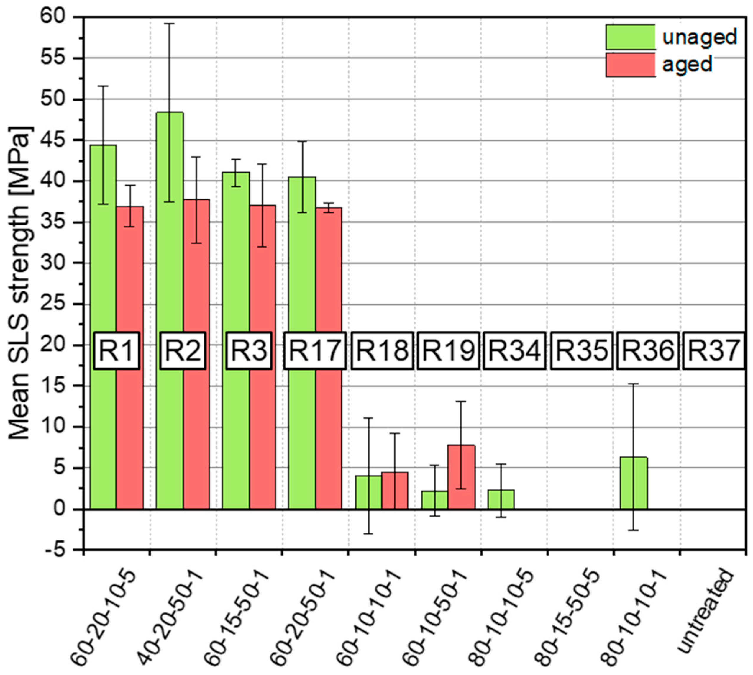
3.1. SLS Strength of the Hybrid AW 6082-T6–CFRP Specimens

The choice of the laser-pretreatment parameter set has a significant influence on the resulting SLS strength of unaged and hydrothermally aged hybrid specimens. While the pretreatment leads to increased mean SLS strengths of 40–45 MPa in the unaged state for R1–3 and R17 of the hybrid specimens, the specimens pretreated with the R18–19, R34, and R36 parameter sets only result in mean SLS strengths around 5 MPa (Figure 3). The standard errors of the unaged and aged R1–3 and R17 as well as of the unaged R18–19, R34, and R36 specimens imply that the differences in SLS strengths in between the differently pretreated specimens are negligible.
The specimens pretreated with the R35 parameter set as well as the untreated reference specimens R37 could not be tested, neither in the unaged nor in the hydrothermally aged state, since all specimens already failed while being mounted in the testing machine. This also occurred with all aged R34 and R36 specimens.
After hydrothermal aging, the mean SLS strength of R1–3 and R17 hybrid specimens drops to values of ~35 MPa. However, except for the R3 specimens, the error bars for the SLS results of the unaged specimens and the mean SLS strengths of the aged specimens are very similar to each other (Figure 3). This also applies for the specimens of R18 and R19. While the SLS strengths of the aged specimens of these sets are slightly elevated compared to the unaged specimens, they can still be considered quite similar also considering the large error bars, which imply that differences are likely negligible. For comparison, the results from the SLS tests of the adhesively bonded AW 6082-T6–E320 specimens from [17] are presented in Section 4, which is further discussed in chapter 4 along with the results of the hybrid specimens.

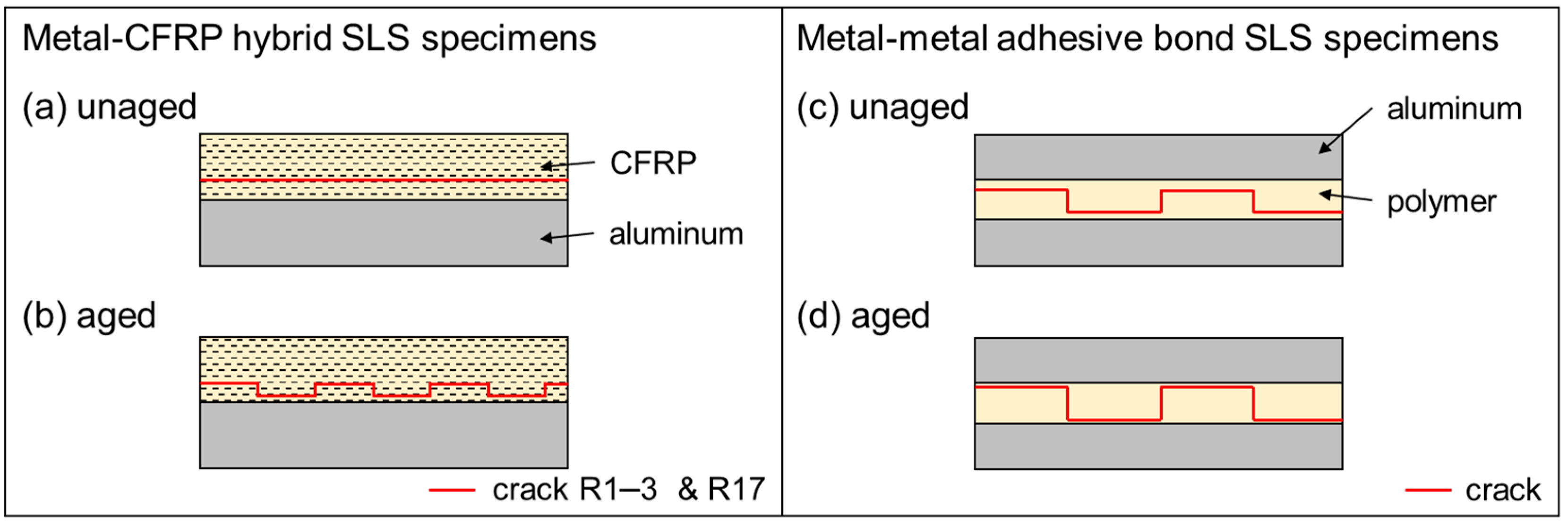
3.2. Analysis of the Fracture Surfaces

Along with the SLS strength, there are also significant differences in the appearance of the fracture surfaces of the SLS specimens, depending on the laser pretreatment parameter set and whether the specimens were hydrothermally aged. The quantification of the remaining CFRP on the metal fracture surfaces and the SEM analysis of unaged R1–R17 specimens reveal that the metal fracture surfaces are completely, or—in the case of R3 specimens—almost completely covered with CFRP (Figure 4 and Figure 5a,b). This indicates a cohesive failure within the CFRP for all of these specimens.
For the unaged specimens pretreated with the R18–19 and R34–36 parameter sets, the surface fraction of the remaining CFRP significantly decreases to values of less than 10% (Figure 4). On one of the fracture surfaces, the structures generated through the laser pretreatment and smaller surface fractions of CFRP are clearly visible (e.g., Figure 5c), while the other side (CFRP fracture surface) presents an imprint of the surface structures in the polymer matrix of the CFRP. Small, randomly distributed fractions of the polymer matrix are still found on the metal fracture surface and are missing on the CFRP fracture surface (e.g., Figure 5d). The fracture surfaces of untreated SLS specimens are very similar but do not show significant amounts of remaining CFRP on the metal side. The polymer matrix is mainly intact. The failure for the R18–19, R34–36, and untreated unaged specimens is, therefore, adhesive or pseudo-adhesive in pattern, since thin layers of polymer on top of the laser-generated surface structures as well as areas with visible metal oxide nanostructures are both found on the fracture surfaces.
Hydrothermal aging further influences the appearance of the fracture surfaces. The remaining CFRP surface fraction on the metal fracture surface of R1–3 and R17 hybrid specimens is significantly reduced to ~70% for R1–2, to ~20% for R3, and to ~55% for R17 specimens (Figure 4). The SEM images of these fracture surfaces reveal that the laser-generated surface structures are now clearly visible in some areas of the surface (e.g., Figure 6a). The second CFRP side of the failed joint, apart from fibers and the polymer matrix, shows an imprint of the laser-generated surface structures (e.g., Figure 6b), which indicates a shift in the main locus of failure from inside the CFRP material toward the interface between the materials and, hence, an increased tendency toward adhesive failure. However, the analysis of the remaining surface fraction of CFRP reveals that the failure of R1, R2, and R17 specimens remains mainly cohesive.
The appearance of the fracture surfaces of the R18–19, R34–36, and untreated specimens also changes slightly. The amount of remaining CFRP on the laser-generated structures further decreases. Randomly distributed areas with filigree, flake-like structures are found on top of the laser-generated structures (Figure 6c, red square). Fewer structures are found on the CFRP fracture surfaces that mimic the shape of the laser-generated structures (Figure 6c,d).
The fracture surfaces of the AW 6082-T6–E320 metal–polymer specimens with the same laser metal surface pretreatments as the AW 6082-T6–CFRP SLS specimens from Ref. [17] are also analyzed. In contrast to those of the unaged R1–3 and R17 hybrid specimens, which present a cohesive failure in the SLS tests (Figure 7a), the patterns of the laser structures are visible on all fracture surfaces of the E320 metal adhesive bond SLS specimens. The locus of failure of the unaged hybrid SLS specimens does not change over the whole fracture surface, but it shifts from the region close to one metal adherent across the polymer to the other metal adherent for the laser-pretreated metal–polymer specimens (Figure 7c). Either an imprint of the laser-generated structures in the polymer, or the structures without or with a thin layer of polymer are visible on the fracture surface (Figure 8). On the fracture surfaces of untreated reference specimens, the locus of failure is similar: one metal adherent is almost completely covered with a thick layer of polymer adhesive and the other without, or with a very thin layer of polymer adhesive.
Furthermore, fracture surfaces of aged, untreated specimens are partly covered with fine structures resembling aluminum hydroxides [17]. Hydrothermal aging changes the locus of failure for the R1–3 and R17 hybrid specimens to a partly adhesive or pseudo-adhesive failure (Figure 7b). For the metal–polymer specimens, the locus of failure is not significantly changed by hydrothermal aging. However, the locus of failure shifts toward the metal surface (Figure 7d). The thickness of the polymer layer on top of the laser-generated structures seems to decrease. Craters appear to be deeper and more details of the surface structures become visible (e.g., Figure 9a,b). Smaller, disconnected polymer layers on the surfaces vanish (e.g., Figure 9c,d).

4. Discussion

The results show the strong dependence between SLS strengths and laser process settings for hybrid metal–CFRP specimens with pretreated metal surfaces. In general, for all laser parameter sets, the pretreatment enhances the mechanical strength of the unaged hybrid SLS specimens compared to the untreated reference. The joint strength of the latter specimens was insufficient even for mounting in the testing setup.
Nevertheless, a difference of ≥30 MPa between the SLS results for the different groups of pretreatment parameter sets is found, pointing to differences in terms of highly and less pronounced surface structures. The results can be split into three groups:
I.
Pretreatments R1 to R3 and R17 with mean SLS strengths of >40 MPa before and >35 MPa after hydrothermal aging;
II.
R18 and R19, which lead to SLS strengths up to 10 MPa before and after hydrothermal aging;
III.
R34 to 36 specimens with less than 10 MPa before and negligible SLS strengths after hydrothermal aging.
Fracture surfaces of specimens from the third group were the only ones that suggested the formation of aluminum hydroxides after the aging step of these untreated samples (Figure 6c) [17].
The SLS strengths of AW 6082-T6–CFRP specimens from group I are similar to the SLS strengths of laser-pretreated AW 6082-T6–E320 joints with different adhesives [15,17]. However, SLS strengths of more than 50 MPa that were obtained in case of the metal–polymer joints could not be reached for the AW 6082-T6–CFRP joints. Since the chemical composition of the laser-pretreated surface and the morphology of the generated surface structures must be expected to be comparable to those from the previous study [15,17], the differences must be related to the CFRP joining partner. The general trend of the resulting SLS strengths for different laser pretreatment parameter sets for hybrid AW 6082-T6–CFRP specimens is found to be similar to that of the AW 6082-T6–E320 specimens.
The best performing pretreatment parameter sets of the metal adhesive bonds are also the most suitable parameter sets for the pretreatment of hybrid specimens (Figure 10). However, there is a much larger difference between the best and least performing pretreatment parameter sets in case of the metal–CFRP joints; the laser-pretreated AW 6082-T6–E320 SLS specimens all present mean SLS strengths of more than 30 MPa in the unaged state and more than 25 MPa after hydrothermal aging, while the SLS strength of the R18-19 and R34-36 metal–CFRP hybrid specimens drops to <10 MPa. Furthermore, even the untreated AW6082-T6–E320 bonded specimens show a mean SLS strength of ~30 MPa in the unaged and ~15 MPa in the aged state, while all untreated hybrid specimens, aged and unaged, fail before testing (Figure 10).
In contrast to the metal–polymer adhesive bonds, differences in the coefficients of thermal expansion of the metal and CFRP component induce intrinsic thermal residual stresses in the production process that lead to a visible elastic deformation of the specimens. In all untreated and in the aged specimens pretreated with the laser parameter sets of R34–R36, these stresses weaken the bonding state to an extent at which very small additional loads (i.e., sample mounting) lead to a complete failure at the interface. For all of these specimens, the resulting micro- and nano-surface enlargement is low. For pretreated surfaces with a high micro- and nano-surface enlargement (R1–R3, R17), i.e., also with a higher amount of chemical bonds between the metal oxide surface and the polymer, the residual stresses can be compensated well (e.g., possibly due to the higher number density of specific chemical bonds or due to slightly higher bond strengths), which also seems to reduce the damage through hydrothermal aging.
Da Silva et al. found that the thickness of the adhesive layer has an influence on the resulting SLS strength of metal–polymer joints, which increases with decreasing thickness of the adhesive layer [23,24]. In metal–FRP joints, the entire FRP matrix thickness can, in the first approximation, be considered as an adhesive layer. However, this is not correct, as finite-element simulations show [25,26], since the embedded fibers of course affect the load distribution differently than an unperturbed matrix.
The influence of the laser-generated surface structures on the SLS strength before and after hydrothermal aging is obvious. The surface enlargement on a micro- and nanoscale, the crater depth, and microstructural features like undercut surface structures, which have been found to correlate with the resulting SLS strength of AW 6082-T6–E320 adhesive joints [17], also play a similar role for the metal–CFRP joints. Those features are known to affect the mechanical strength of metal–composite hybrids [6,7,16], which agrees with this study. The first group (R1–3, R17) of pretreatment parameter sets, which produce surface structures that lead to median micro-surface enlargement values of ~350–560%, median nano-surface enlargement values of ~1400–2700%, and crater depths of ~11–32 µm [17], result in the highest SLS strengths of the hybrid specimens before and after hydrothermal aging.
A drop in the median micro-surface enlargement to values <60% and the median nano-surface enlargement to values below 900% [17] from samples of the second and third groups (R18-19 and R34-36) leads to much weaker SLS strengths. Especially for the micro- and nano-surface enlargement, a certain threshold apparently needs to be surpassed in order to achieve high SLS strengths for unaged and hydrothermally aged metal–CFRP joints. The lower micro- and nano-surface enlargement of the R18-19 metal–CFRP specimens seems to be partly compensated by undercut structures [17]. The decreasing trend of SLS strengths with increasing rank of the laser parameter set is continuous for the metal–polymer joints and shows no large drop from one set to the other as is the case between R17 and R18 for the metal–CFRP specimens (Figure 10). Since the chemistry of the polymer matrix and the chemistry of the amorphous metal oxide films generated by the same laser pretreatments are generally identical (covalent and ionic bonds as well as physiochemical interactions [27]) for the metal–polymer and the metal-CFRP hybrid joints, these differences cannot simply be attributed to a qualitative change in the chemical bonding or the interlocking contribution with undercuts. This further emphasizes the importance of the surface enlargement along with the crater depth and the presence of undercut structures for high-strength, aging-resistant hybrid joints. These hybrid metal–CFRP joints are found to be even more sensitive to changes in these surface features than the corresponding metal–polymer joints.
The laser-generated surface structures also determine the type of failure for the SLS specimens. If the surface enlargement is high and the ablated craters are deep, a complete or at least more than 90% cohesive failure is achieved for unaged hybrid specimens (Figure 4). If the surface enlargement is low and the craters are flat, the fracture surfaces reveal mainly adhesive failure with less than 10% of CFRP remaining on the laser-structured surface of unaged specimens. Hydrothermal aging leads to a shift from mainly cohesive to a mix of cohesive and adhesive failure or completely adhesive failure (Figure 4 and Figure 6). The decrease in remaining CFRP on the fracture surface of aged specimens correlates with the loss of SLS strength. An exception is represented by the parameter set of R3: Two of the three aged R3 samples show mainly adhesive or pseudo-adhesive failure but the testing of all three specimens resulted in SLS strengths of more than 30 MPa. Nevertheless, thicker layers of the matrix polymer are still encountered over a large surface area of the R3 samples’ fracture surfaces.
A shift toward adhesive failure after hydrothermal aging is also seen on the fracture surfaces of AW 6082-T6–E320 metal–polymer joints. The polymer layer on the laser-structured surface becomes thinner and smaller, and unconnected polymer layers vanish completely. For the SLS specimens, this shift correlates as well with the decrease in the mean SLS strength (Figure 10). However, the decrease in SLS strength is less pronounced compared to the hybrid specimens. Specimens that mainly present adhesive failure (e.g., R36 specimens) still reach mean SLS strengths of more than 25 MPa before and about 15 MPa after aging instead of failing before testing.

5. Conclusions

The transferability of the structure–property relationships between laser-generated surface features and adhesive properties from AW 6082-T6–E320 metal–polymer joints to AW 6082-T6–CFRP hybrid bonds was investigated. The following similarities and differences were found:
  • Similar to the AW 6082-T6–E320 joints, the best performing pulsed-laser pretreatments also resulted in the highest SLS strengths for the hybrid AW 6082-T6–CFRP specimens. This is observed consistently before and after hydrothermal aging. High micro- and nanosurface enlargements are found to be particularly important, similar to the case of the metal–polymer joints.
  • In contrast to the AW 6082-T6–E320 bonding, where even poorly optimized laser pretreatments improved the joint properties, for hybrid aluminum–CFRP joining, only well-optimized parameter sets increased the SLS strength. Contrary to the AW 6082-T6–E320 case, some of the metal–CFRP specimens failed even before testing. The results indicate that for aluminum–CFRP joints, a threshold value for the surface enlargement needs to be surpassed in order to achieve high SLS strengths.
  • Hydrothermal aging shifts the failure from predominantly cohesive to an increasingly adhesive failure in the hybrid- and adhesively bonded metal SLS specimens. However, the change in the failure pattern does not generally translate into a major loss in joint strength.
Since the chemical bonds between the metal oxide surface and the polymer adhesive are similar for aluminum–polymer and aluminum–CFRP specimens using the same polymer matrix, the differences in the resulting SLS strengths are attributed to intrinsic thermal residual stresses in the interface of the hybrid specimens. These stresses are induced in the production process of the hybrid specimens due to the different coefficients of thermal expansion of the aluminum and CFRP. The pulsed laser pretreatment generating a high surface enlargement, deep craters, and undercut structures on the metal joint are found to compensate for the negative influence of these stresses. Then, SLS strengths before and after hydrothermal aging, similar to the values for laser-pretreated metal adhesive bonds, are achieved. Hence, these structure–property relationships of AW 6082-T6–E320 metal adhesive bonds can be transferred to AW 6082-T6–CFRP hybrids.

Author Contributions

Conceptualization, J.F., M.L. and J.H.; methodology, J.F., I.L., S.W. and A.D.; validation, J.F., M.L. and J.H.; formal analysis, J.F. and I.L.; investigation, J.F. and I.L.; resources, J.H., F.W. and T.T.; data curation, J.F.; writing—original draft preparation, J.F.; writing—review and editing, J.H., M.L., A.D., S.W., F.W. and T.T.; visualization, J.F.; supervision, J.H., F.W. and T.T.; project administration, J.F., A.D. and S.W.; funding acquisition, J.H., F.W. and T.T. All authors have read and agreed to the published version of the manuscript.

Funding

This research was funded by the Deutsche Forschungsgemeinschaft (DFG, German Research Foundation)—426499947.

Data Availability Statement

The data that support the findings of this study are available from the corresponding author, Jonathan Freund, upon reasonable request.

Conflicts of Interest

The authors declare no conflict of interest.

Appendix A

Table A1. Description of the features of the laser-generated surface structures depending on the pretreatment parameter set.
Parameter SetMicrostructures
(Morphology)
Melt Craters
(Depth)
Nanostructures
(Density and Height)
Undercut
Structures
R1ordered, groove-likedeepestdense and mediumyes
R2complex, overlappingdeepdense and largeyes
R3complex, overlappingmediumdense and largeyes
R17complex, overlappingmediumdense and mediumyes
R18complex, overlappingmediumdense and smallyes
R19ordered, overlappingshallowdense and smallyes
R34ordered, without overlapalmost flatsparse and smallnegligible
R35ordered, without overlapalmost flatsparse and smallnegligible
R36ordered, without overlapalmost flatdense and smallnegligible

References

  1. Kwon, D.S.; Yoon, S.H.; Hwang, H.Y. Effects of residual oils on the adhesion characteristics of metal-CFRP adhesive joints. Compos. Struct. 2019, 207, 240–254. [Google Scholar] [CrossRef]
  2. Reitz, V.; Meinhard, D.; Ruck, S.; Riegel, H.; Knoblauch, V. A comparison of IR- and UV-laser pretreatment to increase the bonding strength of adhesively joined aluminum/CFRP components. Compos. Part A Appl. Sci. Manuf. 2017, 96, 18–27. [Google Scholar] [CrossRef]
  3. Li, H.; Liu, H.; Li, S.; Zhao, Q.; Qin, X. Influence of high pulse fluence infrared laser surface pretreatment parameters on the mechanical properties of CFRP/aluminium alloy adhesive joints. J. Adhes. 2023, 99, 584–605. [Google Scholar] [CrossRef]
  4. Zhang, Z.; Shan, J.; Tan, X.; Zhang, J. Improvement of the laser joining of CFRP and aluminum via laser pre-treatment. Int. J. Adv. Manuf. Technol. 2017, 90, 3465–3472. [Google Scholar] [CrossRef]
  5. Schanz, J.; Meinhard, D.; Dostal, I.; Riegel, H.; De Silva, A.K.M.; Harrison, D.K.; Knoblauch, V. Comprehensive study on the influence of different pretreatment methods and structural adhesives on the shear strength of hybrid CFRP/aluminum joints. J. Adhes. 2022, 98, 1772–1800. [Google Scholar] [CrossRef]
  6. Akman, E.; Bora, M.; Çoban, O.; Oztoprak, B.G. Laser-induced groove optimization for Al/CFRP adhesive joint strength. Int. J. Adhes. Adhes. 2021, 107, 102830. [Google Scholar] [CrossRef]
  7. Trauth, A.; Lohr, C.; Lallinger, B.; Weidenmann, K. Interface characterization of hybrid biocompatible fiber-metal laminates after laser-based surface treatment. Compos. Struct. 2022, 281, 115054. [Google Scholar] [CrossRef]
  8. Davis, M.; Bond, D. Principles and practices of adhesive bonded structural joints and repairs. Int. J. Adhes. Adhes. 1999, 19, 91–105. [Google Scholar] [CrossRef]
  9. Sandeep, R.; Natarajan, A. Advances in joining technologies for the innovation of 21st century lightweight aluminium-CFRP hybrid structures. Proc. Inst. Mech. Eng. Part E J. Process. Mech. Eng. 2022, 236, 1239–1255. [Google Scholar] [CrossRef]
  10. Bjørgum, A.; Lapique, F.; Walmsley, J.; Redford, K. Anodising as pre-treatment for structural bonding. Int. J. Adhes. Adhes. 2003, 23, 401–412. [Google Scholar] [CrossRef]
  11. Schanz, J.; Nester, S.; Meinhard, D.; Pott, T.; Riegel, H.; De Silva, A.K.M.; Harrison, D.K.; Knoblauch, V. Adhesively bonded CFRP/Al joints: Influence of the surface pretreatment on corrosion during salt spray test. Mater. Corros. 2022, 73, 158–170. [Google Scholar] [CrossRef]
  12. Löbbecke, M.; Bayerbasi, T.J.; Bartsch, M.; Haubrich, J. Role of surface structures on long term stability of adhesive joints between Ti–15V–3Cr–3Sn–3Al and polyether-ether-ketone. Int. J. Adhes. Adhes. 2023, 120, 103282. [Google Scholar] [CrossRef]
  13. Baldan, A. Adhesively-bonded joints in metallic alloys, polymers and composite materials: Mechanical and environmental durability performance. J. Mater. Sci. 2004, 39, 4729–4797. [Google Scholar] [CrossRef]
  14. Min, J.; Wan, H.; Carlson, B.E.; Lin, J.; Sun, C. Application of laser ablation in adhesive bonding of metallic materials: A review. Opt. Laser Technol. 2020, 128, 106188. [Google Scholar] [CrossRef]
  15. Irfan, M.; Requena, G.; Haubrich, J. The effect of weak boundary layers on adhesion properties of laser pretreated aluminum alloy EN-AW 6082 surfaces. Int. J. Adhes. Adhes. 2022, 119, 103271. [Google Scholar] [CrossRef]
  16. Ostapiuk, M.; Bieniaś, J. Fracture Analysis and Shear Strength of Aluminum/CFRP and GFRP Adhesive Joint in Fiber Metal Laminates. Materials 2019, 13, 7. [Google Scholar] [CrossRef]
  17. Freund, J.; Löbbecke, M.; Delp, A.; Walther, F.; Wu, S.; Tröster, T.; Haubrich, J. Relationship between laser-generated micro- and nanostructures and the long-term stability of bonded epoxy-aluminum joints. J. Adhes. 2023, 1–31. [Google Scholar] [CrossRef]
  18. DIN EN 515:2017-05; Aluminium und Aluminiumlegierungen_-Halbzeug_-Bezeichnungen der Werkstoffzustände. Deutsche Fassung EN_515:2017; Beuth Verlag GmbH: Berlin/Heidelberg, Germany, 2017.
  19. SGL epo GmbH. SIGRAPREG® C U230-0/NF-E320/39%: Sicherheitsdatenblatt (Safety Data Sheet); Revision no. 1.02; SGL epo GmbH: Willich, Germany, 2019. [Google Scholar]
  20. Wu, S.; Delp, A.; Freund, J.; Walther, F.; Haubrich, J.; Löbbecke, M.; Tröster, T. Adhesion properties of the hybrid system made of laser-structured aluminium EN AW 6082 and CFRP by co-bonding-pressing process. J. Adhes. 2023, 1–29. [Google Scholar] [CrossRef]
  21. DIN EN 1465:2009-07; Klebstoffe_-Bestimmung der Zugscherfestigkeit von Überlappungsklebungen. Deutsche Fassung EN_1465:2009; Beuth Verlag GmbH: Berlin/Heidelberg, Germany, 2009.
  22. Rasband, W.S. ImageJ. Java 1.8.0_172 (64-bit); U. S. National Institutes of Health: Bethesda, MD, USA, 1997–2022. Available online: https://imagej.nih.gov/ij/ (accessed on 11 September 2023).
  23. da Silva, L.F.M.; Rodrigues, T.N.S.S.; Figueiredo, M.A.V.; de Moura, M.F.S.F.; Chousal, J.A.G. Effect of Adhesive Type and Thickness on the Lap Shear Strength. J. Adhes. 2006, 82, 1091–1115. [Google Scholar] [CrossRef]
  24. da Silva, L.F.; das Neves, P.J.; Adams, R.; Wang, A.; Spelt, J. Analytical models of adhesively bonded joints—Part II: Comparative study. Int. J. Adhes. Adhes. 2009, 29, 331–341. [Google Scholar] [CrossRef]
  25. Hundley, J.M.; Hahn, H.T.; Yang, J.-M.; Facciano, A.B. Multi-Scale Modeling of Metal-Composite Interfaces in Titanium-Graphite Fiber Metal Laminates Part I: Molecular Scale. Open J. Compos. Mater. 2011, 1, 19–37. [Google Scholar] [CrossRef]
  26. Hundley, J.M.; Hahn, H.T.; Yang, J.-M.; Facciano, A.B. Multiscale modeling of metal-composite interfaces in titanium-graphite fiber metal laminates part II: Continuum scale. J. Compos. Mater. 2012, 46, 1235–1249. [Google Scholar] [CrossRef]
  27. Li, S.; Wan, H.; Lin, J.; Min, J. Physicochemical interactions between amorphous metal oxide and polymer in metal–polymer hybrid materials. Mater. Des. 2023, 230, 111993. [Google Scholar] [CrossRef]
Figure 1. (a) Hybrid AW 6082-T6-CFRP sheets after water jet cutting, and (b) hybrid SLS specimens with notches.
Jcs 07 00427 g001
Figure 2. (a) Stereomicroscope image of a fracture surface before and (b) after applying a filter to divide the fracture surface into areas with and without remaining CFRP.
Jcs 07 00427 g002
Figure 3. Mean SLS strengths of hybrid AW 6082-T6–CFRP specimens with ten different laser-parameter sets, consisting of frequency, laser power, laser spot overlap, number of scans and masked according to the aforementioned scheme R##.
Jcs 07 00427 g003
Figure 4. Mean CFRP surface fraction on metal fracture surfaces of unaged and aged AW 6082-T6–CFRP hybrid specimens with ten different laser-parameter sets, consisting of frequency, laser power, laser spot overlap, number of scans and masked according to the aforementioned scheme R##.
Jcs 07 00427 g004
Figure 5. SEM images of fracture surfaces of unaged hybrid SLS specimens: metal side (green inset: laser-structured surface for comparison) on the left and CFRP side on the right. (a) R1 metal fracture surface; (b) R1 CFRP fracture surface; (c) R18 metal fracture surface; and (d) R18 CFRP fracture surface (square: missing polymer matrix revealing the carbon fibers) specimens.
Jcs 07 00427 g005
Figure 6. SEM images of fracture surfaces of hybrid SLS specimens aged for 7 days with the metal side on the left and CFRP side on the right of (a,b) R1 and (c,d) R36 specimens with filigree flake-like structures on the metal surface.
Jcs 07 00427 g006
Figure 7. Schematics of the crack evolution in unaged (a) and aged (b) AW 6082-T6–CFRP and unaged (c) and aged (d) AW 6082-T6–E320 specimens.
Jcs 07 00427 g007
Figure 8. Fracture surfaces of unaged AW 6082-T6–E320 SLS specimens pretreated with the (a) R1 and (b) R36 parameter set.
Jcs 07 00427 g008
Figure 9. SEM images of fracture surfaces of AW 6082-T6-E320 SLS specimens: (a) R1 unaged; (b) R1 aged; (c) R36 unaged; and (d) R36 aged.
Jcs 07 00427 g009
Figure 10. Mean SLS strengths of the single-lap shear tests performed with hybrid AW 6082-T6–CFRP specimens and with AW 6082-T6–E320 metal adhesive joints from [13] for comparison.
Jcs 07 00427 g010
Table 1. Parameter sets for the pulsed laser metal surface pretreatment.
RFrequency (kHz)Laser Power (W)Laser Spot Overlap (%)Number of Scans (×)
16020105
24020501
36015501
176020501
186010101
196010501
348010105
358015505
368010101
Disclaimer/Publisher’s Note: The statements, opinions and data contained in all publications are solely those of the individual author(s) and contributor(s) and not of MDPI and/or the editor(s). MDPI and/or the editor(s) disclaim responsibility for any injury to people or property resulting from any ideas, methods, instructions or products referred to in the content.

