Article

Influence on the Flexural Behaviour of High-Volume Fly-Ash-Based Concrete Slab Reinforced with Sustainable Glass-Fibre-Reinforced Polymer Sheets

by
Chinnasamy Samy Madan
1,
Krithika Panchapakesan
1,
Potlapalli Venkata Anil Reddy
1,
Philip Saratha Joanna
1,*,
Jessy Rooby
1,
Beulah Gnana Ananthi Gurupatham
2 and
Krishanu Roy
3,*
1
Department of Civil Engineering, Hindustan Institute of Technology and Science, Chennai 603103, India
2
Department of Civil Engineering, Anna University, Chennai 600025, India
3
School of Engineering, Civil Engineering, The University of Waikato, Hamilton 3216, New Zealand
*
Authors to whom correspondence should be addressed.
J. Compos. Sci. 2022, 6(6), 169; https://doi.org/10.3390/jcs6060169
Submission received: 21 May 2022 / Revised: 2 June 2022 / Accepted: 9 June 2022 / Published: 10 June 2022
(This article belongs to the Special Issue Sustainable Composite Construction Materials)

Abstract

:
Concrete structures provided with steel bars may undergo deterioration due to fatigue and corrosion, which leads to an increase in repair and maintenance costs. An innovative approach to eliminating these drawbacks lies in the utilisation of glass-fibre-reinforced polymer (GFRP) sheets as reinforcement in concrete structures instead of steel bars. This article relates to the investigation of the flexural behaviour of ordinary portland cement (OPC) concrete slabs and high-volume fly ash (HVFA) concrete slabs reinforced with bi-directional GFRP sheets. Slab specimens were cast with 60% fly ash as a replacement for cement and provided with a 1 mm-thick GFRP sheet in 2, 3 and 4 layers. The flexural behaviour of slabs reinforced with GFRP sheets was compared with that of the slabs reinforced with steel bars. Experiment results such as cracking behaviour, failure modes and load–deflection, load–strain and moment–curvature relationships of the slab specimens are presented. Subsequently, the nonlinear finite-element method (NLFEM) using ANSYS Workbench 2022-R1 was carried out and compared with the experimental results. The results obtained from the numerical investigation correlated with the experimental results. The experimental investigation showed that the HVFA concrete slabs reinforced with GFRP sheet provided a better alternative compared to the steel reinforcement, which led to sustainable construction.

1. Introduction

There has been a significant increase worldwide in the utilisation of fibre-reinforced polymer (FRP) [1]. FRP has been accepted as an alternate material to traditional steel reinforcement. The various types of FRP composites include aramid-fibre-reinforced polymers (AFRP), carbon-fibre-reinforced polymers (CFRP) and glass-fibre-reinforced polymers (GFRP). FRPs are available in various forms such as rods, sheets and plates. FRP offers several applications in concrete structures as they offer high resistance to corrosion, lightweight, ease of handling and high strength [2,3]. GFRP is most often used because of its lower cost than that of other FRP materials. GFRP sheet is used as an external reinforcement on the top surface of the concrete [4].
The structural elements reinforced with GFRP bars/sheets are usually over reinforced sections, which exhibit brittle failure. The use of nonmagnetic GFRP rebars as reinforcement is gaining importance in preventing deterioration in the structural integrity in concrete structures due to its corrosion resistance, lower maintenance costs and higher tensile strength than steel reinforcement [5,6,7,8]. Bidirectional binding of GFRP sheets with concrete attains superior mechanical performance, acting as a substitute for steel rods. Research carried out on slabs, beams and columns with the GFRP rebars as reinforcement has reported their structural performance as on par with the steel reinforcement [9,10,11,12]. The GFRP rods could be utilised as reinforcement in prestressed concrete members and reinforced concrete members, ground anchors and for strengthening the existing concrete structures [13,14,15,16]. The ultimate load-carrying capacity of the concrete slab reinforced with GFRP mesh is more than the engineered cementitious composite (ECC) slab made by polyvinyl alcohol fibres with 60% fly ash was used as a replacement for cement. Hence, reinforcing the concrete slab with GFRP mesh would be a better choice when compared to the ECC slab [17].
In the construction industry, concrete consists of Ordinary Portland Cement (OPC). It is the most commonly used construction material because of its raw material availability and low cost. However, OPC production requires argillaceous and calcareous materials and is energy-intensive. The main reasons for the emission of greenhouse gas during the production of OPC are calcination and fossil-fuel combustion [18]. The manufacturing of OPC contributes to around 8% of global carbon-dioxide emissions [19]. Waste materials from the industries act as an ingredient for conventional concrete, which helps in bringing down waste disposal problems. Many industrial waste materials such as ground granulated blast-furnace slag (GGBS), fly ash and micro silica have the potential to replace cement in concrete [20].
Fly ash, a by-product of the thermal power plant, is the widely accepted pozzolanic material for the replacement of OPC in concrete. The use of fly ash in concrete is increasing due to improvements in workability, strength and durability. Reinforced concrete beams with 50% fly ash show a 10% increase in moment capacity compared with conventional concrete [21]. Some drawbacks are seen when cement is replaced by fly ash as it attains poor strength at its earlier stage due to slow polymerization action [22,23,24,25]. Incorporation of micro silica (MS) in concrete enhances the mechanical properties related to uniformity, workability, strength, impermeability, durability, constructability, resistance to chemical attacks and reinforcement corrosion, and increases its compressive strength more than that of cementitious materials [26]. To enhance the workability, a chemical admixture known as superplasticiser (SP) was added in order to reduce the water content of the concrete mixtures [27].
Beams with 50% of fly ash as a replacement to cement attain a strength less than the conventional concrete at 28 days of curing [28,29]. A durable structure with less greenhouse-gas emission and with less energy could be obtained by the addition of fly ash to the concrete [30,31,32]. The electrical strain gauges were attached to measure the upward movement of the slabs on one corner. This arrangement of electrical gauges was kept constant throughout all the testing of the slab specimens [33]. The replacement of GFRP rods in place of steel as reinforcement in both OPC and HVFA slab specimens improves the flexural strength [34] Test results show lower split tensile and compressive strength for higher mix percentage influencing the minimum strength of the concrete. Structural elements with 50% fly ash have been found at later ages [35]. The wrapping of GFRP sheets drastically improves the stress-strain, strength and behaviour of fibres under various cooling regimes and heating temperatures [36]. With the application of GFRP sheets, a significant increase in the load-carrying capacity of the column was found. With the increase in the number of layers of GFRP, the load-carrying capacity was found to be increased [37].
An extensive literature review shows the potential of using fly ash in concrete. Despite the extensive use of GFRP sheets in the strengthening and repair of concrete structures, utilisation of GFRP sheets as reinforcement in structural elements is scanty. Hence, this paper investigates the possibility of using GFRP sheets as reinforcement in OPC/fly ash concrete slabs. Experimental investigations were carried out on 16 slabs, in which 12 slabs were reinforced with GFRP sheets 1 mm thick in 2, 3 and 4 layers, and 4 slabs were reinforced with steel bars. Parameters such as load-deflection behaviour, crack pattern, failure modes, moment-curvature behaviour and load–strain relationship were used for examination of all the slabs. This study also implements a nonlinear finite-element method (FEM) using ANSYS Workbench 2022-R1 [38] software to numerically investigate the overall structural performance of the slab specimens with reference to the ultimate load and deflection of slab specimens reinforced with steel/GFRP sheets.

2. Materials and Methods

2.1. Ingredients of OPC/HVFA Concrete

The slabs cast with M25 grade concrete consisted of 53-grade ordinary portland cement (OPC) having a specific gravity of 3.1, crushed granite coarse aggregate of 20 mm nominal size conforming to IS:383, manufactured sand (M-sand) as fine aggregate and 10% micro silica by weight of cementitious material. In the fly-ash concrete, 60% of cement was replaced by Class F-type fly ash. The mix design of the concrete is shown in Table 1. To increase workability, 0.3% of Master Glenium sky 8233 superplasticizers were added with concrete as per IS 9103. Details of the chemical composition of Class F fly ash are listed in Table 2. The mix design of concrete arrived as per the Indian standard IS: 10262 and IS: 456.

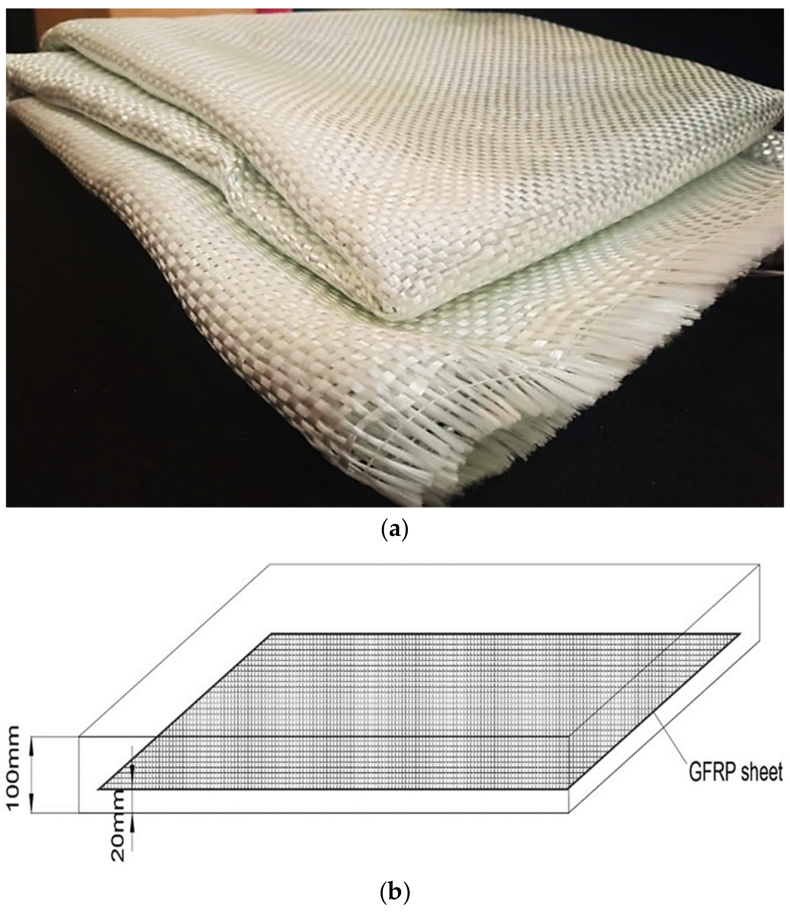
2.2. Reinforcing System

The glass-fibre-reinforced polymer sheets were used as the reinforcing members in the OPC/fly ash-based concrete slabs. The GFRP sheets (E-glass fibre type) are of woven-type bidirectional mat, having a thickness of 1 mm with a fibre density of 2.6 g/cm3. The first layer of GFRP sheets was laid on the fresh concrete at a depth of 20 mm from the bottom, and then it was folded to form the second layer, and then the concreting was completed. Similarly, it was laid for slabs with 3 layers and 4 layers of GFRP sheets. Figure 1 shows the GFRP sheets used as reinforcement in the slabs and the schematic view of placing the sheets in the slab. The test methods were conducted by manufacturers concerning the ASTM D3774/D3801 and ISO 10119/10618 standards. The specifications of the GFRP sheets are shown in Table 3. For comparison, the OPC/fly-ash-based slabs reinforced with conventional steel bars were also cast and tested. The steel rods of grade Fe 550D and having a diameter of 10 mm were reinforced with the centre-to-centre spacing of 130 mm along the longer direction and 240 mm along the shorter direction. Steel rods were placed at 20 mm depth from the bottom.

3. Experimental Investigation

3.1. Specimen Geometry and Detailing

In this experimental work, a total of 16 slabs 1000 mm long with a cross-section of 450 mm × 100 mm were cast and tested at the end of 56 days of curing. They are categorised into two groups, of which Group I consists of eight slabs of OPC concrete reinforced with steel bars/GFRP sheets in layers 2, 3 and 4. Group II consists of eight slabs made of HVFA concrete reinforced with steel bars/GFRP sheets in layers 2, 3 and 4. Two slabs were cast in each series. A five-lettered designation was allotted to the slab specimens, where the first two letters indicate the reinforcement type as steel-reinforced (SR)/glass-fibre-reinforced polymer sheets (GS). The third letter indicates the type of concrete, i.e., OPC concrete as (C)/HVFA-based concrete as (F). The fourth identity denotes the number of layers of GFRP sheets as 2, 3 and 4, and the fifth identity denotes the trial numbers.

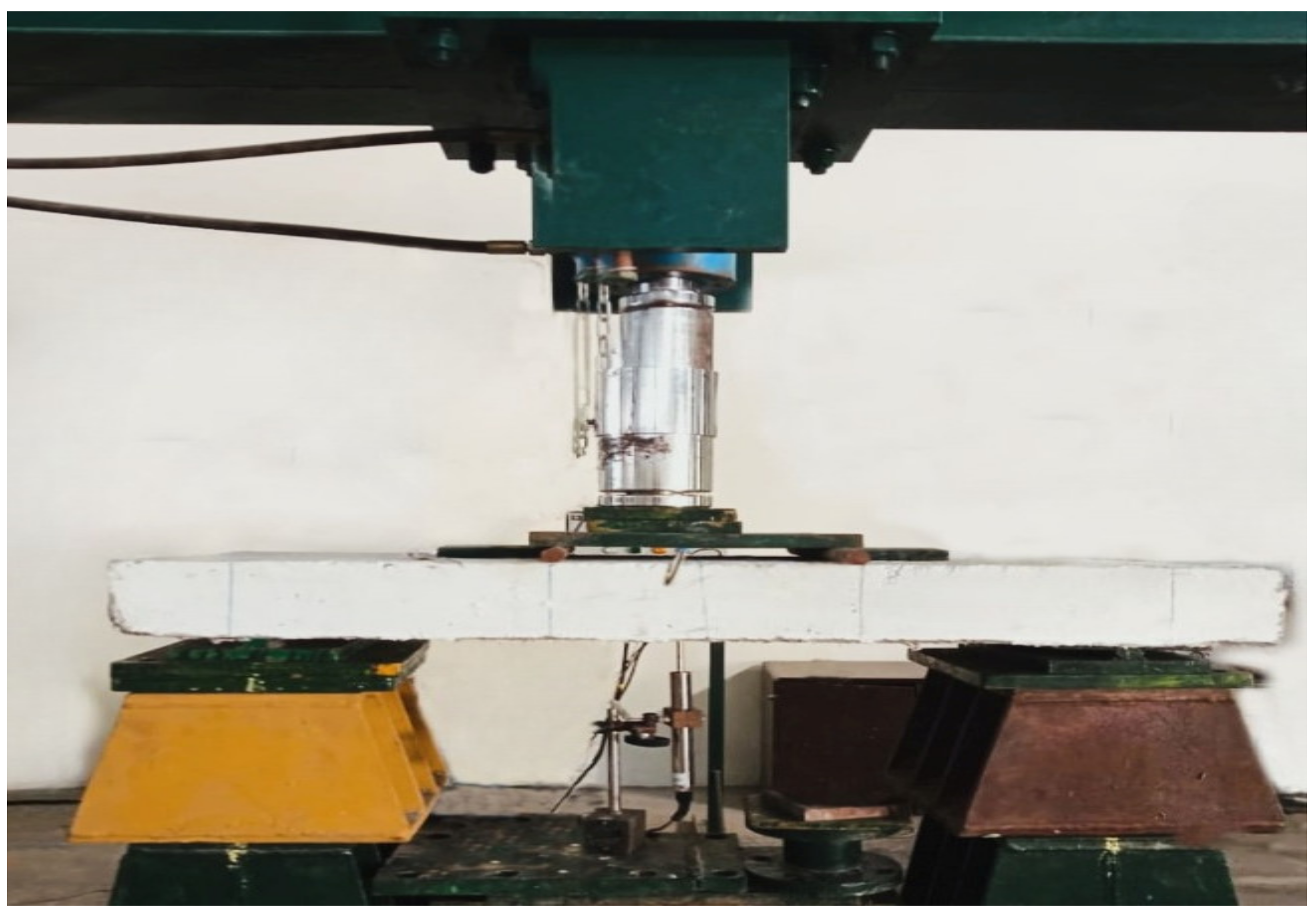
3.2. Experimental Set-Up

The one-way slabs were subjected to two-point flexural loading. The slab specimens were tested with roller support at one end and hinge support at the other end. A spreader beam was placed for the application of two-point loading to the slab specimens. The specimens were subjected to static load through a loading frame of 400 kN capacity. Electrical strain gauges were placed at the bottom of the GFRP sheet, and they were protected using coating tape to avoid any accidental damage while pouring concrete; and also on the top concrete surface of the slab for measurement of the compressive strain at midspan. The slabs were instrumented with linear voltage displacement transducers (LVDT), which were placed at the mid-span to monitor the deflection. A load of 2 kN/min was applied incrementally through a hydraulic jack via load cell up to the failure of the slabs. Electrical signals captured from the strain gauges and the LVDT were transmitted to the computer via a data logger. The schematic view of the experimental set-up for testing the slab specimens is shown in Figure 2 and the testing of the slab specimens is shown in Figure 3.

4. Results and Discussion

4.1. Cracking Behaviour

Propagation of cracks and the failure mode of the slab specimens are shown in Figure 4, Figure 5, Figure 6 and Figure 7. The summary of the test results of the slab specimens is shown in Table 4. The average initial crack load of Group-I slab specimens GSC-2, GSC-3, GSC-4 and SRC were 8.5 kN, 14.5 kN, 6.5 kN and 16 kN, respectively. The average first crack load of Group-II slab specimens GSF-2, GSF-3, GSF-4 and SRF were 5.8 kN, 14.1 kN, 5.4 kN and 18.8 kN, respectively. Four modes of failure were observed in the slab specimens. The slab specimens SRC and SRF exhibited flexural cracks under both the loading points (Mode-I). Slab specimens GSC-2 and GSF-2 exhibited flexural crack with concrete crushing under the mid-span of the slab specimens (Mode-II). At the bottom of GSC-3 and GSF-3 slabs, fine vertical cracks began at an average load of 14.5 kN and 14.1 KN, respectively. With an increase in load, the crack propagated towards the top of the slab with crack widening. At an average load of 21.5 KN, which is 90% of the ultimate average load under the loading point, a flexural crack with the initiation of horizontal cracks was formed at the junction of GFRP sheet and concrete, which may be due to the debonding of GFRP sheets and concrete surface (Mode-III). In the case of GSC-4 and GSF-4, flexural cracks at an average load of 6.5 kN and 5.4 kN, respectively, with the subsequent formation of horizontal cracks were noticed over the entire span of the slab (Mode-IV). In the slabs reinforced with GFRP sheets, the cracks propagated from the bottom of the slab to the top of the slab exhibited brittle failure at the ultimate load level.

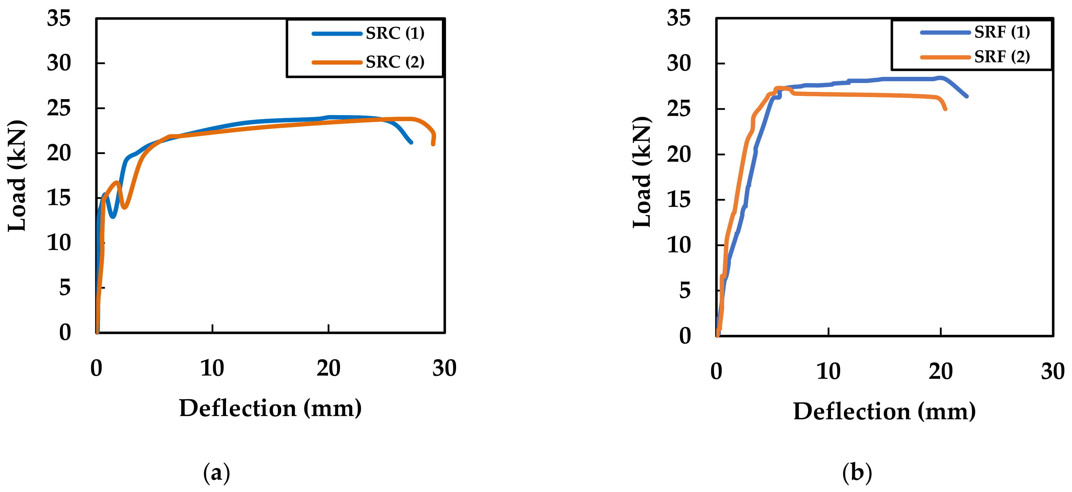
4.2. Load–Deflection Behaviour

Details relating to load–deflection of the Group-I and Group-II slab specimens tested after 56 days of curing were plotted. All the slab specimens showed linear elastic behaviour up to the initial crack, and beyond that, the behaviour was nonlinear. Details of the load-deflection behaviour of slabs GSC-2 and GSF-2; GSC-3 and GSF-3; GSC-4 and GSF-4; and SRC and SRF are shown in Figure 8, Figure 9, Figure 10 and Figure 11, respectively. The average ultimate load-carrying capacity of the Group-I specimens (OPC slab) GSC-2, GSC-3, GSC-4 and SRC was 17.15 kN, 23.85 kN, 15.95 kN and 23.9 kN, respectively. The average ultimate load-carrying capacity of the Group-II specimens (fly ash slab) GSF-2, GSF-3, GSF-4 and SRF was 16.9 kN, 23.8 kN, 15.6 kN and 27.9 kN, respectively. The SRF slab specimens reinforced with steel showed a 17% increase in their average ultimate load-carrying capacity compared with SRC slabs. The average ultimate load-carrying slab specimens GSC-2, GSC-4, GSF-2 and GSF-4 showed 28%, 33%, 29% and 34%, respectively, less than the SRC slab specimens. However, the average ultimate load-carrying capacity of GSC-3 and GSF-3 was the same as that of SRC. In the case of GSC-4 and GSF-4, flexural cracks at an average load of 6.5 kN and 5.4 kN, respectively, with the subsequent formation of horizontal cracks over the entire span of the slab, were observed. As the horizontal cracks formed at the earlier stage due to the debonding of the sheets, the reduction in ultimate load was therefore observed. The deflection in the slab specimens reinforced with GFRP sheets was less than the deflection in the slab specimens reinforced with steel bars.

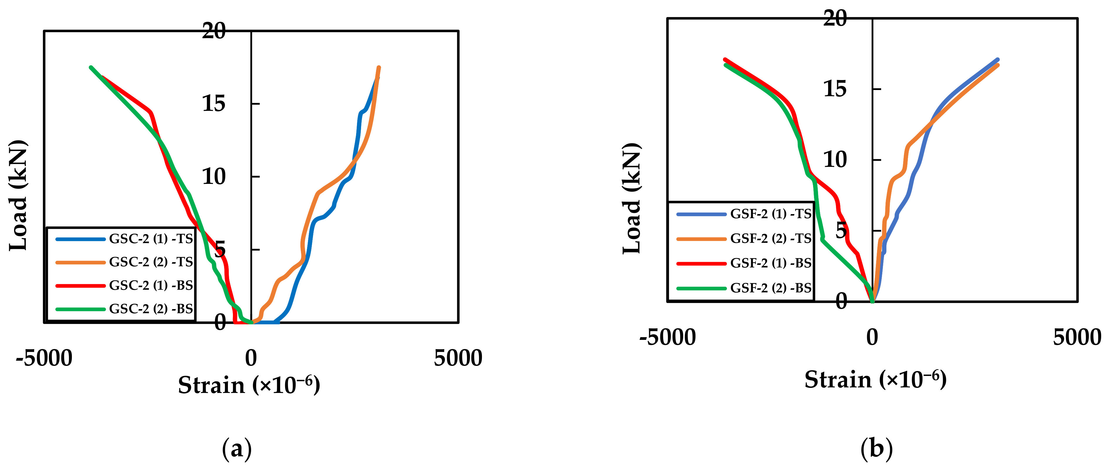
4.3. Strain Distribution

The top positive strain indicates the compressive strain in concrete, while the bottom negative strain indicates the tensile strain in the GFRP sheets/steel bars. For each load increment, the strain values experienced by both strain gauges at the mid-span region of the slab were plotted. The load vs. strain variations in the slab specimens were GSC-2 and GSF-2; GSC-3 and GSF-3; GSC-4 and GSF-4; and SRC and SRF are shown in Figure 12, Figure 13, Figure 14 and Figure 15, respectively. The top strain development in the Group-I specimens (OPC slab) and Group-II specimens (HVFA slab) reinforced with steel bars/GFRP sheets range from 2985 µ to 3099 µ. The bottom strain development in the Group-I specimens (OPC slab) and Group-II specimens (HVFA slab) reinforced with GFRP sheets ranges from 3317 µ to 4315 µ. However, the strain measured at the bottom of the steel bars in the SRC and SRF at failure ranges from 19,080 µ to 21,900 µ, which was almost 21% of the failure strain of the GFRP sheets. The result shows that the top and the bottom strain of GSC-3 and GSF-3 is higher when compared with the slab reinforced with GFRP sheets of two layers and four layers.

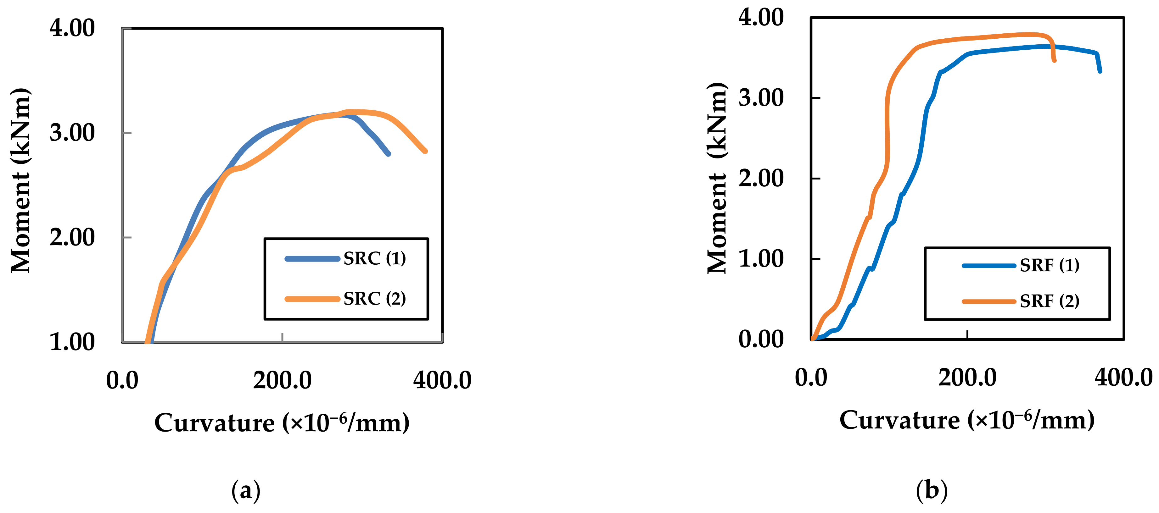
4.4. Moment–Curvature

The moment–curvature diagram defines the ultimate capacity of the slab elements and is also used to access the energy absorption capacity of the slab elements. The moment–curvature relationship was calculated for all the slab specimens based upon the top strain (OPC/HVFA concrete) and the bottom strain (steel/GFRP sheets). The moment–curvature relationship of GSC-2 and GSF-2; GSC-3 and GSF-3; GSC-4 and GSF-4 and SRC and SRF are shown in Figure 16, Figure 17, Figure 18 and Figure 19, respectively.
The following equation was used for the calculation of curvature (∅),
= ε c + ε r d
where,
d—Effective depth of the slab
εr—Tensile strain in the reinforcement (steel/GFRP sheets)
εc—Compressive strain in concrete
Moment vs. curvature relationships showed the average ultimate moment-carrying capacity of the slabs of Group-I: GSC-2, GSC-3, GSC-4 and SRC as 2.28 kNm, 3.18 kNm, 2.13 kNm and 3.18 kNm, respectively. The average ultimate moment-carrying capacity of the slabs of Group-II: GSF-2, GSF-3, GSF-4 and SRF were 2.25 kNm, 3.17 kNm, 2.08 kNm and 3.25 kNm, respectively. The moment-carrying capacity of the slabs reinforced with GFRP sheets (GSC-3 and GSF-3) was the same as that of the slab specimen reinforced with the steel bars (SRC). Table 5 shows the details of the overall performance details of the OPC/HVFA concrete slab reinforced with steel rod/GFRP sheets.

5. Numerical Analysis and Consecutive Models

The nonlinear finite-element analysis (NLFEA) comprises modelling of the slab specimens, introducing the element type, material properties, boundary conditions, meshing and loading. To obtain accurate results from the numerical simulations, all the necessary components such as OPC/HVFA concrete, steel rods and GFRP sheets were modelled properly with the aid of nonlinear stress–strain graphs and the material properties. Numerical analysis using ANSYS Workbench 2022-R1 was carried out to simulate the OPC/HVFA concrete slabs reinforced with steel bars/GFRP sheets.
From the experimental investigation, it was observed that the OPC/HVFA concrete slabs reinforced with three layers of GFRP sheets had the highest ultimate load-carrying capacity when compared with the slabs reinforced with two and four layers of GFRP sheets. Hence, the slab specimens SRC, SRF, GSC-3 and GSF-3 were analysed using nonlinear finite-element analysis.

5.1. Considerations for Element Types

In ANSYS, M25 grade concrete was modelled using SOLID 65, which is an eight-noded element consisting of 3 degrees of freedom in x, y and z directions and capable of cracking in three orthogonal directions. The GFRP sheet was modelled with four-noded SHELL 181 elements. Two-noded LINK 180 element was used to model the steel reinforcement [39]. The bonded contact was used between the GFRP sheet and concrete to prevent separation between them.

5.2. Modelling and Numerical Solution

The modelling of the slab specimens was performed via a geometry design modeller in the ANSYS Workbench 2022-R1. The effect of crack pattern, stress, strain, ultimate load, ultimate deflection and displacement of concrete with different types of end conditions could be analysed in the ANSYS [40,41,42]. Geometry with the support conditions and load points of application and 3D meshed modelling of the slab specimen are shown in Figure 20. Steel bars/GFRP sheet reinforcement with a sheet thickness of 3 mm was provided at 20 mm from the bottom.
In NLFEM, an incremental loading that was the same as the sequence of loading used for the experiment was applied until the failure of the specimens. The load–deflection parameters were recorded during the loading step. The ultimate deflection of the SRC, SRF, GSC-3 and GSF-3 slabs obtained from the numerical analysis is shown in Figure 21. The ultimate load of the slab specimen SRC, SRF, GSC-3 and GSF-3 are 23 kN, 27 kN, 23.5 kN and 23 kN, respectively, with the ultimate deflection of 15.9 mm, 16.4 mm, 2.5 mm and 2.2 mm, respectively.

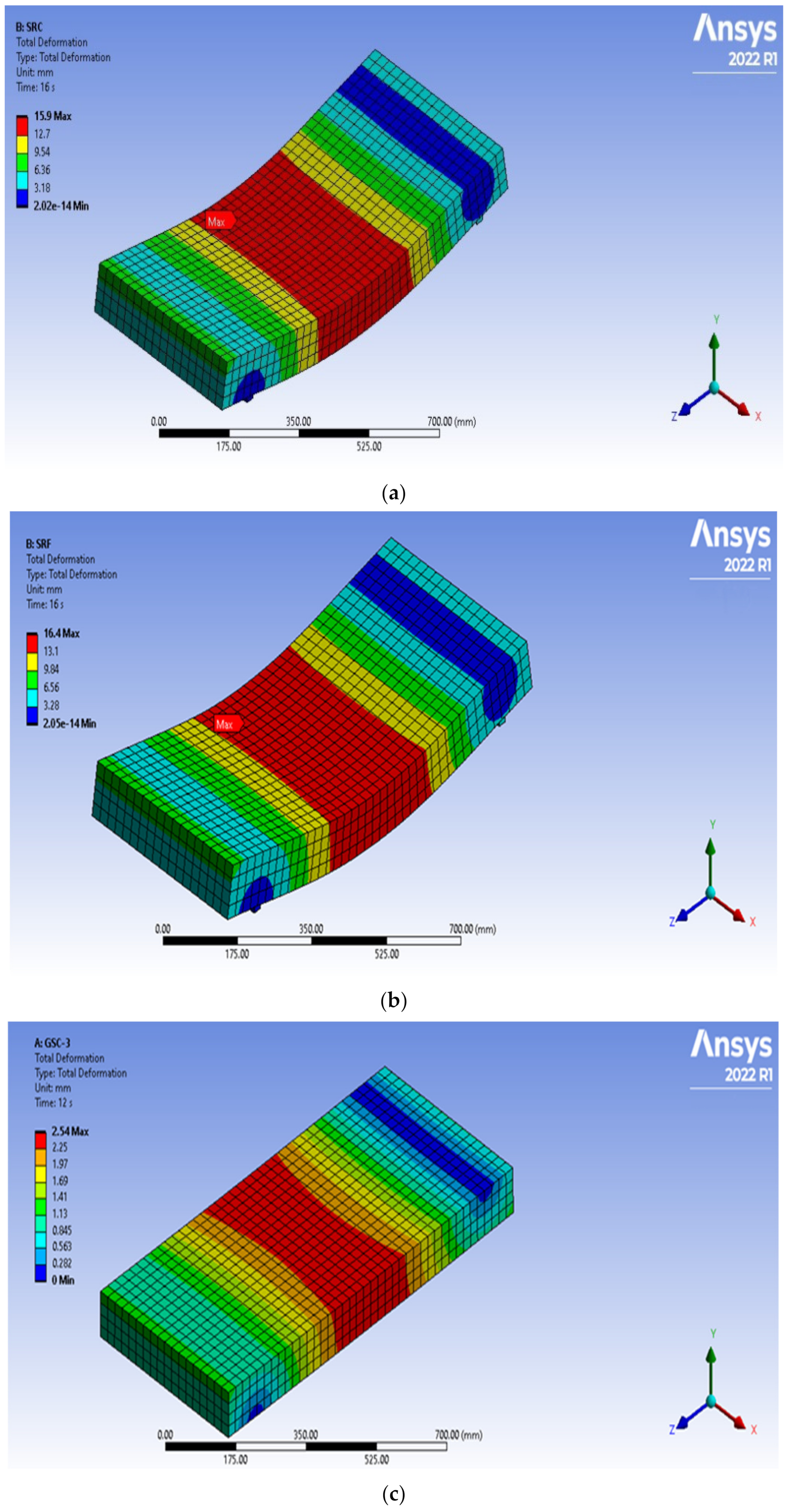
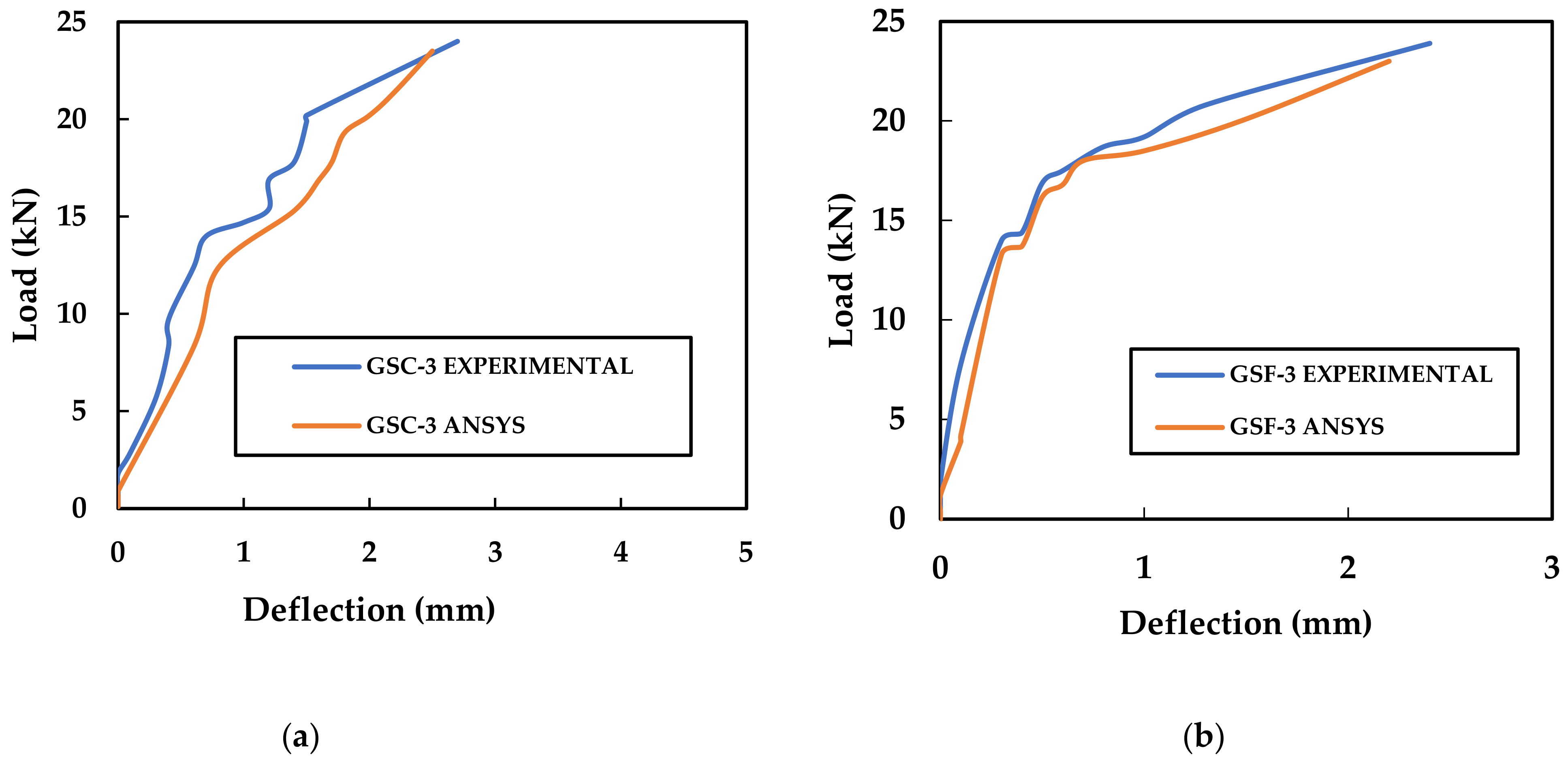
5.3. Comparison of Experimental Results with NLFEA Results

The comparison between experimental and NLFEA results is shown in Table 6. Less than 10% difference in the ultimate load and ultimate deflection of the SRC, SRF, GSC-3 and GSF-3 was noticed between the experimental and NLFEA results. Figure 22 shows the comparison of the load–deflection relationship of the SRC and SRF, and Figure 23 shows the comparison of the load–deflection relationship of the GSC-3 and GSF-3 obtained from the NLFEA analysis and the experimental investigation. From the results, it is observed that both the experimental and numerical results are in good correlation. Hence, ANSYS 2022-R1 software can be used for the analysis of fly-ash concrete slabs reinforced with a GFRP sheet.

6. Conclusions

This study presents the results of an experimental investigation involving sixteen simply supported slab specimens made of OPC/HVFA concrete reinforced with steel bars/GFRP sheets.
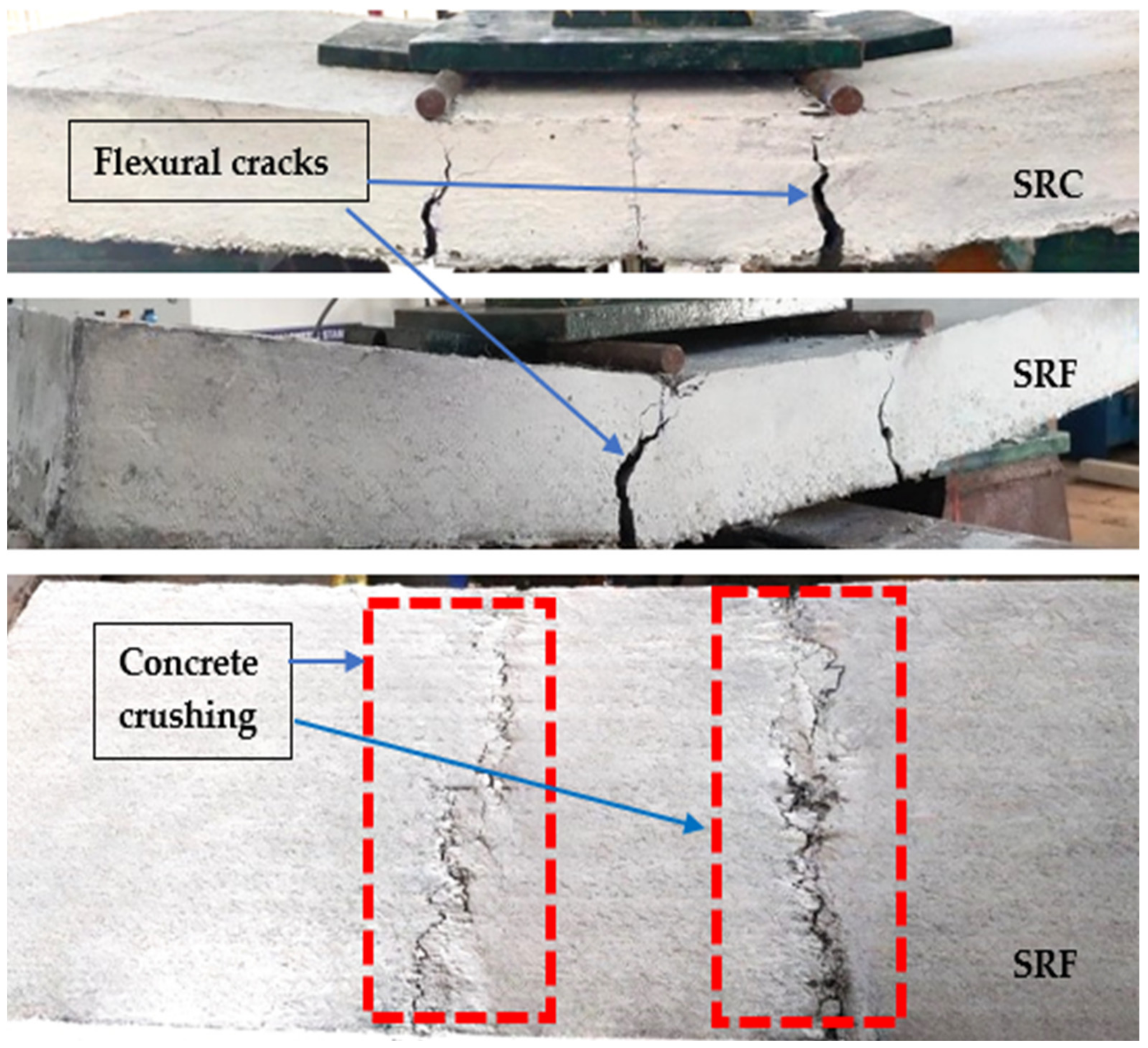
  • HVFA slabs reinforced with the steel bars (SRF) recorded a 17% increase in their ultimate load-carrying capacity compared with the OPC slabs reinforced with the steel bars (SRC).
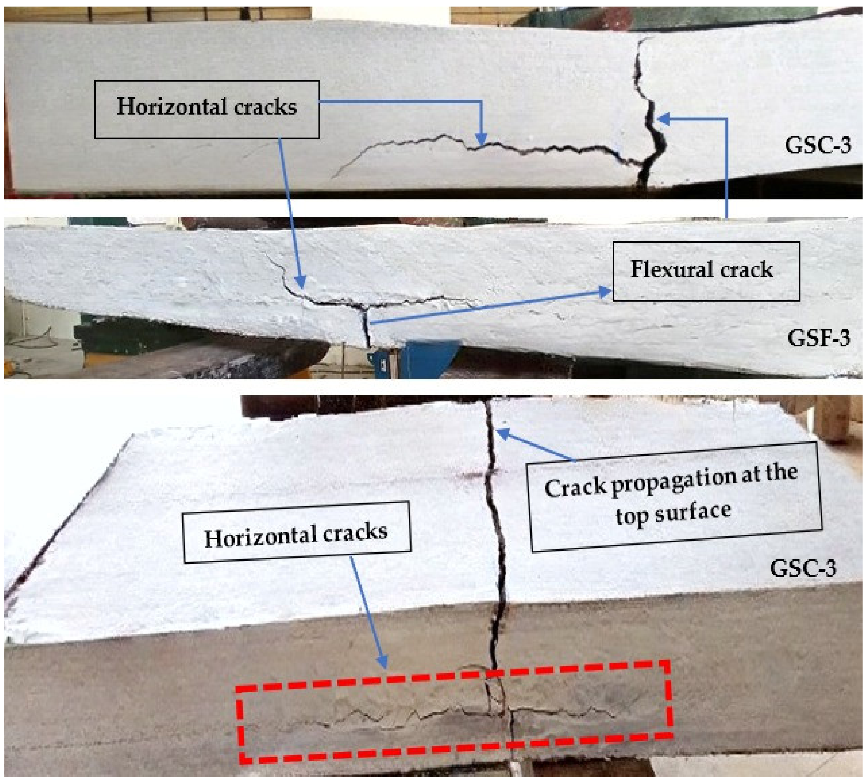
  • All the specimens failed due to the formation of flexural cracks that propagate to the top surface at failure with concrete crushing. Slabs reinforced with two layers of GFRP sheets failed in the formation of flexural cracks under the two-loading point. However, the slab reinforced with three layers and four layers of GFRP sheets showed flexural cracks as well as horizontal cracks.
  • The average ultimate load-carrying capacity of OPC/HVFA concrete slabs reinforced with three layers of GFRP sheets (GSC-3/GSF-3) has the same strength as that of slabs reinforced with the steel bars (SRC).
  • The ultimate average load-carrying capacity of a slab reinforced with three layers of GFRP sheets (GSC-3 and GSF-3) is more than that of the slabs reinforced with two and four layers (GSC-2, GSC-4, GSF-2 and GSF-4) by 39%, 49%, 41% and 53%, respectively.
  • Less than 10% difference in the ultimate load and ultimate deflection of SRC, SRF, GSC-3 and GSF-3 was observed between the experimental and NLFEM results. Hence, ANSYS Workbench 2022-R1 software could be used for the numerical analysis of fly-ash concrete slabs reinforced with a GFRP sheet.
From this study, it is evident that a one-way slab cast with OPC concrete/high-volume fly-ash concrete could be reinforced with GFRP sheets instead of steel bars. This study also reinstates the potential use of high-volume fly ash as a replacement of cement in concrete slab. Thus, a reduction in OPC content in concrete could be an effective way of mitigating the effect of greenhouse-gas emissions, leading to sustainable construction.

Author Contributions

C.S.M., K.P. and P.V.A.R.: Conceptualised the model and conducted the experiments. P.S.J., J.R., B.G.A.G. and K.R.: Supervised the research as well as the analysis of results. P.S.J., J.R., C.S.M. and K.P.: Introduced the idea of static loading in this project; designed the slab; wrote, reviewed and submitted the paper; and collaborated in and coordinated the research. P.S.J., J.R., B.G.A.G. and K.R.: Suggested and chose the journal for submission. P.S.J., B.G.A.G. and K.R.: Participated in the manuscript revision phase. All authors have read and agreed to the published version of the manuscript.

Funding

This research received no external funding.

Institutional Review Board Statement

Not applicable.

Informed Consent Statement

Not applicable.

Data Availability Statement

The data presented in this study are available on request from the corresponding author.

Conflicts of Interest

This manuscript has not been submitted to, nor is it under review by, another journal or other publishing venue. The authors have no affiliation with any organisation with a direct or indirect financial interest in the subject matter discussed in the manuscript. The authors declare no conflict of interest.

References

  1. Ji, H.; Son, B.; Ma, Z. Evaluation of Composite Sandwich Bridge Decks with Hybrid FRP-Steel Core. J. Bridg. Eng. 2009, 14, 36–44. [Google Scholar] [CrossRef]
  2. Shin, Y.S.; Lee, C. Flexural behaviour of reinforced concrete beams strengthened with carbon fibre-reinforced polymer laminates at different levels of sustaining load. ACI Struct. J. 2003, 100, 231–239. [Google Scholar]
  3. Teng, J.G.; Chen, J.F.; Smith, S.T.; Lam, L. Behaviour and strength of FRP-strengthened RC structures: A state-of-the-art review. Proc. Inst. Civ. Eng.-Struct. Build. 2003, 156, 51–62. [Google Scholar] [CrossRef]
  4. Djamaluddin, R.; Irmawaty, R.; Tata, A. Flexural Capacity of Reinforced Concrete Beams Strengthened Using GFRP Sheet after Fatigue Loading for Sustainable Construction. Key Eng. Mater. 2016, 692, 66–73. [Google Scholar] [CrossRef]
  5. Sethi, A.K.; Kinjawadekar, T.A.; Nagarajan, P.; Shashikala, A.P. Design of Flexural Members Reinforced with GFRP Bars. IOP Conf. Ser. Mater. Sci. Eng. 2020, 936, 012036. [Google Scholar] [CrossRef]
  6. Abdalla, H.A. Evaluation of deflection in concrete members reinforced with fibre reinforced polymer (FRP) bars. Compos. Struct. 2002, 56, 63–71. [Google Scholar] [CrossRef]
  7. Ferdous, W.; Manalo, A.; Aravinthan, T. Effect of beam orientation on the static behaviour of phenolic core sandwich composites with different shear span-to-depth ratios. Compos. Struct. 2017, 168, 292–304. [Google Scholar] [CrossRef]
  8. Manalo, A. Behaviour of fibre composite sandwich structures under short and asymmetrical beam shear tests. Compos. Struct. 2013, 99, 339–349. [Google Scholar] [CrossRef]
  9. Maranan, G.; Manalo, A.; Benmokrane, B.; Karunasena, W.; Mendis, P. Evaluation of the flexural strength and serviceability of geopolymer concrete beams reinforced with glass-fibre-reinforced polymer (GFRP) bars. Eng. Struct. 2015, 101, 529–541. [Google Scholar] [CrossRef]
  10. Bouguerra, K.; Ahmed, E.; El-Gamal, S.; Benmokrane, B. Testing of full-scale concrete bridge deck slabs reinforced with fibre-reinforced polymer (FRP) bars. Constr. Build. Mater. 2011, 25, 3956–3965. [Google Scholar] [CrossRef]
  11. ACI. ACI Guide for the Design and Construction of Concrete Reinforced with FRP Bars; Report 440R-96; ACI: Detroit, MI, USA, 2001; pp. 1023–1034. [Google Scholar]
  12. ACI. State-of-the-Art Report on Fibre Reinforced Plastic (FRP) Reinforcement for Concrete Structures; ACI: Detroit, MI, USA, 2004. [Google Scholar]
  13. Grace, N.F.; Abdel-Sayed, G.; Ragheb, W.F. Strengthening of Concrete Beams Using Innovative Fibre-Reinforced Polymer Fabric. ACI Struct. J. 2002, 99, 692–700. [Google Scholar]
  14. Li, V.C.; Wang, S. Flexural behaviours of glass fibre reinforced polymer (GFRP) reinforced engineered cementitious composite beams. ACI Mater. J. 2002, 99, 11–20. [Google Scholar]
  15. Razaqpur, A.G.; Sevecova, D.; Cheung, M.S. Rational method for calculating deflection of fibre-reinforced polymer reinforced beams. ACI Struct. J. 2000, 97, 175–184. [Google Scholar]
  16. Sen, R.; Mullins, G.; Salem, T. Durability of E-glass/vinyl ester reinforcement in alkaline solution. ACI Struct. J. 2002, 99, 369–375. [Google Scholar]
  17. Chinnasamy, M.; Ajithkumar, R.; Singh, A.; Yangzom, D.; Parvati, T.; Joanna, P. Comparative study on the behaviour of textile reinforced concrete slab with engineered cementitious composite slab. Mater. Today Proc. 2020, 33, 1175–1180. [Google Scholar] [CrossRef]
  18. Laila, L.R.; Gurupatham, B.G.A.; Roy, K.; Lim, J.B.P. Effect of super absorbent polymer on microstructural and mechanical properties of concrete blends using granite pulver. Struct. Concr. 2020, 22, E898–E915. [Google Scholar] [CrossRef]
  19. He, Z.; Zhu, X.; Wang, J.; Mu, M.; Wang, Y. Comparison of CO2 emissions from OPC and recycled cement production. Constr. Build. Mater. 2019, 211, 965–973. [Google Scholar] [CrossRef]
  20. Sivaramakrishnan, R.; Anbarasu, E. Experimental Study on High-Performance Concrete by 40% Partial Replacement of Cementitious Material with Micro Silica, GGBS & Fly-Ash. IJESC 2020, 10, 25227–25231. [Google Scholar]
  21. Joanna, P.S.; Rooby, J.; Prabhavathy, A.; Preetha, R.; Pillai, C.S. Behaviour of reinforced concrete beams with 50 per cent fly ash. Int. J. Civ. Eng. Technol. 2013, 4, 36–48. [Google Scholar]
  22. Partha, S.D.; Pradip, N.; Prabir, K.S. Strength and Permeation Properties of Slag Blended Fly Ash Based Geopolymer Concrete. Adv. Mater. Res. 2013, 651, 168–173. [Google Scholar] [CrossRef]
  23. Nazari, A.; Riahi, S. Improvement compressive strength of concrete in different curing media by Al2O3 nanoparticles. Mater. Sci. Eng. A 2011, 528, 1183–1191. [Google Scholar] [CrossRef]
  24. Hosseini, P.; Hosseinpourpia, R.; Pajum, A.; Khodavirdi, M.M.; Izadi, H.; Vaezi, A. Effect of nano-particles and aminosilane interaction on the performances of cement-based composites: An experimental study. Constr. Build. Mater. 2014, 66, 113–124. [Google Scholar] [CrossRef]
  25. Maravelaki-Kalaitzaki, P.; Agioutantis, Z.; Lionakis, E.; Stavroulaki, M.; Perdikatsis, V. Physico-chemical and mechanical characterization of hydraulic mortars containing nano-titania for restoration applications. Cem. Concr. Compos. 2013, 36, 33–41. [Google Scholar] [CrossRef]
  26. Laila, L.R.; Gurupatham, B.G.A.; Roy, K.; Lim, J.B.P. Influence of super absorbent polymer on mechanical, rheological, durability, and microstructural properties of self-compacting concrete using non-biodegradable granite pulver. Struct. Concr. 2020, 22, E1093–E1116. [Google Scholar] [CrossRef]
  27. Rana, A.K.; Rana, S.; Kumari, A.; Kiran, V. Significance of nanotechnology in construction engineering. IJRTE 2009, 1, 46. [Google Scholar]
  28. Arezoumandi, M.; Volz, J.S.; Myers, J.J. Shear Behavior of High-Volume Fly Ash Concrete versus Conventional Concrete. J. Mater. Civ. Eng. 2013, 25, 1506–1513. [Google Scholar] [CrossRef]
  29. Rao, R.M.; Mohan, S.; Sekar, S.K. Shear Resistance of High Volume Fly ash Reinforced Concrete Beams without Web Reinforcement. Int. J. Civ. Struct. Eng. 2001, 1, 986–993. [Google Scholar]
  30. Agarwal, V.; Gupta, S.M.; Sachdeva, S.N. High volume fly ash concrete—A green concrete. J. Environ. Res. Dev. 2012, 6, 884–887. [Google Scholar]
  31. Lowe, D.; Roy, K.; Das, R.; Clifton, C.; Lim, J. Full-scale experiments on splitting behaviour of concrete slabs in steel-concrete composite beams with shear stud connection. Structures 2020, 23, 126–138. [Google Scholar] [CrossRef]
  32. Madan, C.S.; Munuswamy, S.; Joanna, P.S.; Gurupatham, B.G.A.; Roy, K. Comparison of the Flexural Behavior of High-Volume Fly AshBased Concrete Slab Reinforced with GFRP Bars and Steel Bars. J. Compos. Sci. 2022, 6, 157. [Google Scholar] [CrossRef]
  33. Kim, H.-K.; Lee, H. Use of power plant bottom ash as fine and coarse aggregates in high-strength concrete. Constr. Build. Mater. 2011, 25, 1115–1122. [Google Scholar] [CrossRef]
  34. Balakrishnan, B.; Awal, A.A. Mechanical Properties and Thermal Resistance of High Volume Fly Ash Concrete for Energy Efficiency in Building Construction. Key Eng. Mater. 2016, 678, 99–108. [Google Scholar] [CrossRef]
  35. Aravind Raj, P.S.; Divahar, R.; Sangeetha, S.P.; Naveen Kumar, K.; Ganesh, D.; Sabitha, S. Sustainable Development of Structural Joint made using High Volume Fly-Ash concrete. Int. J. Adv. Sci. Technol. 2020, 29, 6850–6857. [Google Scholar]
  36. Abadel, A.; Abbas, H.; Albidah, A.; Almusallam, T.; Al-Salloum, Y. Effectiveness of GFRP strengthening of normal and high strength fibre reinforced concrete after exposure to heating and cooling. Eng. Sci. Technol. Int. J. 2022, 36, 101147. [Google Scholar] [CrossRef]
  37. Shukla, S.; Waghmare, M.V. Strengthening of RC Column Using GFRP. Int. J. Res. Appl. Sci. Eng. Technol. 2022, 10, 1217–1224. [Google Scholar] [CrossRef]
  38. ANSYS Mechanical APDL Verification Set; ANSYS Inc.: Canonsburg, PA, USA, 2014.
  39. Sandrasekaran, S.; Praveen Kumar, A. Numerical Modeling of Square Steel Members Wrapped by CFRP Composites. Int. J. Innov. Technol. Explor. Eng. 2019, 8, 3082–3087. [Google Scholar] [CrossRef]
  40. Adam, M.A.; Erfan, A.M.; Habib, F.A.; El-Sayed, T.A. Structural Behavior of High-Strength Concrete Slabs Reinforced with GFRP Bars. Polymers 2021, 13, 2997. [Google Scholar] [CrossRef]
  41. Jayajothi, P.; Kumutha, R.; Vijai, K. Finite element analysis of FRP strengthened RC beams using Ansys. Asian J. Civ. Eng. 2013, 14, 631–642. [Google Scholar]
  42. Gherbi, A.; Dahmani, L.; Boudjemia, A. Study on two way reinforced concrete slab using Ansys with different boundary conditions and loading. World Acad. Sci. Eng. Technol. Int. J. Civ. Environ. Eng. 2018, 12, 1151–1156. [Google Scholar]
Figure 1. (a) Glass-fibre-reinforced polymer (GFRP) sheet (b) Schematic view of placing the sheet.
Jcs 06 00169 g001
Figure 2. Schematic view of experimental set-up.
Jcs 06 00169 g002
Figure 3. Testing of the slab specimens.
Jcs 06 00169 g003
Figure 4. Crack propagation and failure mode of Mode-I slab specimens.
Jcs 06 00169 g004
Figure 5. Crack propagation and failure mode of Mode-II slab specimens.
Jcs 06 00169 g005
Figure 6. Crack propagation and failure mode of Mode-III slab specimen.
Jcs 06 00169 g006
Figure 7. Crack propagation and the failure modes Mode-IV slab specimens.
Jcs 06 00169 g007
Figure 8. Load–deflection behaviour of (a) GSC-2 and (b) GSF-2.
Jcs 06 00169 g008
Figure 9. Load–deflection behaviour of (a) GSC-3 and (b) GSF-3.
Jcs 06 00169 g009
Figure 10. Load–deflection behaviour of (a) GSC-4 and (b) GSF-4.
Jcs 06 00169 g010
Figure 11. Load–deflection behaviour of (a) SRC and (b) SRF.
Jcs 06 00169 g011
Figure 12. Load–strain behaviour of (a) GSC-2 and (b) GSF-2. TS—top strain, BS—bottom strain.
Jcs 06 00169 g012
Figure 13. Load–strain behaviour of (a) GSC-3 and (b) GSF-3. TS—top strain, BS—bottom strain.
Jcs 06 00169 g013
Figure 14. Load–strain behaviour of (a) GSC-4 and (b) GSF-4. TS—top strain, BS—bottom strain.
Jcs 06 00169 g014
Figure 15. Load–strain behaviour of (a) SRC and (b) SRF. TS—top strain, BS—bottom strain.
Jcs 06 00169 g015
Figure 16. Moment–curvature behaviour of (a) GSC 2 and (b) GSF 2.
Jcs 06 00169 g016
Figure 17. Moment–curvature behaviour of (a) GSC-3 and (b) GSF-3.
Jcs 06 00169 g017
Figure 18. Moment–curvature behaviour of (a) GSC-4 and (b) GSF-4.
Jcs 06 00169 g018
Figure 19. Moment–curvature behaviour of (a) SRC and (b) SRF.
Jcs 06 00169 g019
Figure 20. Slab specimen (a) Geometry and (b) 3D meshed model.
Jcs 06 00169 g020
Figure 21. Ultimate deflection of slab (a) SRC, (b) SRF, (c) GSC-3, (d) GSF-3.
Jcs 06 00169 g021aJcs 06 00169 g021b
Figure 22. Comparison between experimental and numerical load–deflection relationship of (a) SRC and (b) SRF.
Jcs 06 00169 g022
Figure 23. Comparison between experimental and numerical load–deflection behaviour of (a) GSC-3 and (b) GSF-3.
Jcs 06 00169 g023
Table 1. Mix proportion of concrete.
Materials/Type of ConcreteCementFly AshMicrosilicaM SandAggregateWaterSuper Plasticiser (%)
OPC concrete1--2.163.420.50.3
60% HVFA0.40.60.12.13.320.50.3
Table 2. Chemical properties of fly ash.
Chemical CompositionContent (% by Mass)
SiO252.52
Al2O332.63
Fe2O26.16
SO34.95
LOI1.08
MnO0.03
NAI-200.02
CaoNil
Table 3. Specification of the GFRP sheets.
ParticularsSpecification
Aerial weight (GSM)400
Tensile strength (N/mm2)2700
Modulus of elasticity (kN/mm2)73
Poisson’s ratio0.3
The thickness of GFRP sheet (mm)1
Elongation at break (%)5
Fibre density (g/cm3)2.6
Table 4. Summary of test results of the slab specimens.
CategorySlab DesignationTrial NumbersInitial Crack Load (KN)Ultimate Load (KN)Modes of Failure
GROUP-IGSC-2Trial 1
Trial 2
8.3
8.7
16.8
17.5
Mode-II
Mode-II
GSC-3Trial 1
Trial 2
14.2
14.7
23.7
24
Mode-III
Mode-III
GSC-4Trial 1
Trial 2
6.7
6.3
16.4
15.5
Mode-IV
Mode-IV
SRCTrial 1
Trial 2
16.3
15.7
23.8
24
Mode-I
Mode-I
GROUP-IIGSF-2Trial 1
Trial 2
5.9
5.7
17.1
16.7
Mode-II
Mode-II
GSF-3Trial 1
Trial 2
14.1
14
23.9
23.7
Mode-II
Mode-II
GSF-4Trial 1
Trial 2
5.2
5.6
15.3
15.9
Mode-IV
Mode-IV
SRFTrial 1
Trial 2
18.5
19.1
27.3
28.5
Mode-I
Mode-I
Table 5. Overall performance details of the concrete slab reinforced with steel rod/GFRP sheets.
CategorySlab
Designation
Max.
Load (Pu)
(kN)
Ultimate Moment (MExp)
(kNm)
Ultimate Strain
in Concrete
at Max Load
( ε cu )
%
Ultimate Strain in
Reinforcement
at Max Load
( ε f )
%
GROUP-IGSC-2 (1)16.82.240.310.36
GSC-2 (2)17.52.330.310.39
GSC-3 (1)23.73.160.310.43
GSC-3 (2)243.200.310.43
GSC-4 (1)16.42.190.300.35
GSC-4 (2)15.52.070.300.34
SRC (1)23.83.170.292.01
SRC (2)24.03.200.311.91
GROUP-IIGSF-2 (1)17.12.280.310.36
GSF-2 (2)16.72.220.300.36
GSF-3 (1)23.93.190.310.41
GSF-3 (2)23.73.160.310.42
GSF-4 (1)15.32.040.300.33
GSF-4 (2)15.92.120.300.33
SRF (1)27.33.700.302.03
SRF (2)28.53.640.312.19
Table 6. Comparison between experimental and numerical results.
SpecimenUltimate Load (kN)Deflection at Mid-Span (mm)
ExperimentalNLFEA (ANSYS)ExperimentalNLFEA (ANSYS)
SRC242316.215.9
SRF28.52717.916.4
GSC-32423.52.72.5
GSF-323.9232.42.2
Publisher’s Note: MDPI stays neutral with regard to jurisdictional claims in published maps and institutional affiliations.

