
Three-Dimensional Thermo-Mechanical Elastic Analysis of Functionally Graded Five Layers Composite Sandwich Plate on Winkler Foundations

Abstract
:1. Introduction
2. Problem Formulation
3. Numerical Results and Discussions
3.1. Three-Layers Sandwich Plate
3.2. Five-Layer FGM Sandwich Plate
3.3. Numerical Results and Discussions
4. Conclusions
Author Contributions
Funding
Institutional Review Board Statement
Informed Consent Statement
Data Availability Statement
Conflicts of Interest
Nomenclature
| Width of the plate | |
| elements of matrices for the kth layer | |
| Length of the plate | |
| , | Elastic modules of the metal and ceramic phases, respectively. |
| Density of foundation reaction force | |
| Shear Modulus | |
| Total thickens of the sandwich plate | |
| Cover sheet thickness | |
| Adhesive thickness | |
| Core thickness | |
| Layer number | |
| elastic foundation stiffness | |
| Moment resultants for the kth layer | |
| Force resultants for the kth layer | |
| n | Power law index |
| Material properties of the ceramic phase | |
| Material properties of the metal phase | |
| Uniform distributed load | |
| The elements of the stiffness matrix | |
| stiffness of core | |
| stiffness of skin | |
| Transverse shear stress results for the kth layer | |
| Ratio stiffness of skin to stiffness of the core | |
| T | Surrounding temperature |
| U | Strain energy |
| Displacement component in x-direction | |
| Strain energy of the foundation | |
| Virtual strain energy | |
| Displacement component in the y direction | |
| Volume fraction of the ceramic phase within the face sheet | |
| Displacement component in the z-direction | |
| Dimensionless displacement component in the z-direction | |
| z | Thickness direction |
| Coefficient of expansion thermal for Elastollan R3000 core or vinyl ester | |
| Coefficients of expansion thermal for the metal and ceramic phases, respectively. | |
| Strain components in the kth layer | |
| Shear correction factor | |
| Poisson ratio of Elastollan R3000 core or vinyl ester | |
| Poisson’s ratios of the ceramic and metal phases, respectively. | |
| Stress components in the kth layer | |
| Dimensionless Stress components | |
| Shear Stress components in the kth layer | |
| Dimensionless Shear Stress components | |
| material volume | |
| rotations of the normal lines to the midplane about the y-axis | |
| rotations of the normal lines to the midplane about the x-axis. |
Appendix A
References
- Koizumi, M. FGM activities in Japan. Compos. Part B Eng. 1997, 28, 1–4. [Google Scholar] [CrossRef]
- Nguyen-Xuan, H.; Tran, L.V.; Nguyen-Thoi, T.; Vu-Do, H. Analysis of functionally graded plates using an edge-based smoothed finite element method. Compos. Struct. 2011, 93, 3019–3039. [Google Scholar] [CrossRef]
- Kerr, A.D. Elastic and Viscoelastic Foundation Models. J. Appl. Mech. 1964, 31, 491–498. [Google Scholar] [CrossRef]
- Benferhat, R.; Daouadji, T.H.; Mansour, M.S. Free vibration analysis of FG plates resting on an elastic foundation and based on the neutral surface concept using higher-order shear deformation theory. Comptes Rendus Mec. 2016, 344, 631–641. [Google Scholar] [CrossRef]
- Mantari, J.; Granados, E. A refined FSDT for the static analysis of functionally graded sandwich plates. Thin-Walled Struct. 2015, 90, 150–158. [Google Scholar] [CrossRef]
- Zenkour, A.M. The refined sinusoidal theory for FGM plates on elastic foundations. Int. J. Mech. Sci. 2009, 51, 869–880. [Google Scholar] [CrossRef]
- Thai, H.-T.; Nguyen, T.-K.; Vo, T.P.; Lee, J. Analysis of functionally graded sandwich plates using a new first-order shear deformation theory. Eur. J. Mech. A/Solids 2014, 45, 211–225. [Google Scholar] [CrossRef] [Green Version]
- Thai, H.-T.; Choi, D.-H. A simple first-order shear deformation theory for the bending and free vibration analysis of functionally graded plates. Compos. Struct. 2013, 101, 332–340. [Google Scholar] [CrossRef]
- Natarajan, S.; Manickam, G. Bending and vibration of functionally graded material sandwich plates using an accurate theory. Finite Elements Anal. Des. 2012, 57, 32–42. [Google Scholar] [CrossRef] [Green Version]
- Xu, Y.J.; Wang, L.L.; Du, H.Y. Analysis of Heating Steady Temperature Field in an Al1100/Ti-6Al-4V/SiC 2D-FGM Plane Plate by FEM. Key Eng. Mater. 2011, 450, 235–238. [Google Scholar] [CrossRef]
- Ferreira, A.; Fasshauer, G.; Batra, R.; Rodrigues, J. Static deformations and vibration analysis of composite and sandwich plates using a layerwise theory and RBF-PS discretizations with optimal shape parameter. Compos. Struct. 2008, 86, 328–343. [Google Scholar] [CrossRef]
- Kapuria, S.; Achary, G. An efficient higher order zigzag theory for laminated plates subjected to thermal loading. Int. J. Solids Struct. 2004, 41, 4661–4684. [Google Scholar] [CrossRef]
- Shodja, H.; HaftBaradaran, H.; Asghari, M. A thermoelasticity solution of sandwich structures with functionally graded coating. Compos. Sci. Technol. 2006, 67, 1073–1080. [Google Scholar] [CrossRef]
- Garg, N.; Karkhanis, R.S.; Sahoo, R.; Maiti, P.R.; Singh, B.N. Trigonometric zigzag theory for static analysis of laminated composite and sandwich plates under hygro-thermo-mechanical loading. Compos. Struct. 2018, 209, 460–471. [Google Scholar] [CrossRef]
- Mechab, B.; Mechab, I.; Benaissa, S. Composites: Part B Analysis of thick orthotropic laminated composite plates based on higher order shear deformation theory by the new function under thermo-mechanical loading. Compos. Part B 2012, 43, 1453–1458. [Google Scholar] [CrossRef]
- Moleiro, F.; Correia, V.F.; Ferreira, A.; Reddy, J. Fully coupled thermo-mechanical analysis of multilayered plates with embedded FGM skins or core layers using a layerwise mixed model. Compos. Struct. 2018, 210, 971–996. [Google Scholar] [CrossRef]
- Raissi, H.; Shishesaz, M.; Moradi, S. Applications of higher order shear deformation theories on stress distribution in a five layer sandwich plate. Appl. Comput. Mech. 2017, 48, 233–252. [Google Scholar] [CrossRef]
- Kardooni, M.R.; Shishesaz, M.; Moradi, S.; Mosalmani, R. Free Vibrational Analysis of a Functionally Graded Five-Layer Sandwich Plate Resting on a Winkler Elastic Foundation in a Thermal Environment. J. Compos. Sci. 2022, 6, 325. [Google Scholar] [CrossRef]
- Shishehsaz, M.; Raissi, H.; Moradi, S. Stress distribution in a five-layer circular sandwich composite plate based on the third and hyperbolic shear deformation theories. Mech. Adv. Mater. Struct. 2019, 27, 927–940. [Google Scholar] [CrossRef]
- Tounsi, A.; Houari, M.S.A.; Benyoucef, S.; Bedia, E.A.A. A refined trigonometric shear deformation theory for thermoelastic bending of functionally graded sandwich plates. Aerosp. Sci. Technol. 2013, 24, 209–220. [Google Scholar] [CrossRef]
- Mahmoudi, A.; Benyoucef, S.; Tounsi, A.; Benachour, A.; Bedia, E.A.A.; Mahmoud, S. A refined quasi-3D shear deformation theory for thermo-mechanical behavior of functionally graded sandwich plates on elastic foundations. J. Sandw. Struct. Mater. 2017, 21, 1906–1929. [Google Scholar] [CrossRef]
- Zhou, W.; Zhang, R.; Ai, S.; He, R.; Pei, Y.; Fang, D. Load distribution in threads of porous metal–ceramic functionally graded composite joints subjected to thermomechanical loading. J. Compos. Struct. 2015, 134, 680–688. [Google Scholar] [CrossRef] [Green Version]
- Miteva, A.; Bouzekova-Penkova, A. Module for wireless communication in aerospace vehicles. Aerosp. Res. Bulg. 2021, 33, 195–209. [Google Scholar] [CrossRef]
- Reddy, J.N. Mechanics of Laminated Composite Plates and Shells; CRC Press: Boca Raton, FL, USA, 2004. [Google Scholar] [CrossRef]
- Birman, V.; Bert, C.W. On the Choice of Shear Correction Factor in Sandwich Structures. J. Sandw. Struct. Mater. 2002, 4, 83–95. [Google Scholar] [CrossRef]
- Srinivas, S.; Rao, A. Bending, vibration and buckling of simply supported thick orthotropic rectangular plates and laminates. Int. J. Solids Struct. 1970, 6, 1463–1481. [Google Scholar] [CrossRef]
- Ferreira, A. Analysis of Composite Plates Using a Layerwise Theory and Multiquadrics Discretization. Mech. Adv. Mater. Struct. 2005, 12, 99–112. [Google Scholar] [CrossRef]
- Plaseied, A.; Fatemi, A. Deformation response and constitutive modeling of vinyl ester polymer including strain rate and temperature effects. J. Mater. Sci. 2008, 43, 1191–1199. [Google Scholar] [CrossRef]
- Elastollan BASF Company, Ellastollan Physical and Mechanical Properties Manual Book of Thermoplastic Polyuerthane Elastomers(TPU), Ellastollan@Product Range. Available online: www.elastollan.de (accessed on 1 November 2022).
- Kahya, V.; Turan, M. Vibration and stability analysis of functionally graded sandwich beams by a multi-layer finite element. Compos. Part B Eng. 2018, 146, 198–212. [Google Scholar] [CrossRef]
- Ziaee, S.; Palmese, G.R. Effects of temperature on cure kinetics and mechanical properties of vinyl-ester resins. J. Polym. Sci. Part B Polym. Phys. 1999, 37, 725–744. [Google Scholar] [CrossRef]
- Liao, S.-H.; Hung, C.-H.; Ma, C.-C.M.; Yen, C.-Y.; Lin, Y.-F.; Weng, C.-C. Preparation and properties of carbon nanotube-reinforced vinyl ester/nanocomposite bipolar plates for polymer electrolyte membrane fuel cells. J. Power Sources 2008, 176, 175–182. [Google Scholar] [CrossRef]


| R | Method | ||||||||
|---|---|---|---|---|---|---|---|---|---|
| 5 | Exact [26] | 258.97 | 60.353 | 46.623 | 9.3402 | 38.49 | 30.097 | 6.161 | 3.2675 |
| Ferreira [27] | 257.523 | 59.9675 | 46.2906 | 9.258 | 38.321 | 29.974 | 5.9948 | 2.3901 | |
| FE | 250.8 | 57.26 | 45 | 8.56 | 36.45 | 28.97 | 5.5 | 3.346 | |
| %Difference | 3.2 | 5.1 | 3.5 | 8.4 | 5.3 | 3.7 | 10.8 | 2.4 | |
| Elastic Modulus of Vinyl Ester (GPa) | Temperature (°C) |
|---|---|
| 3.4 | RT |
| 3.13 | 50 |
| 2.8 | 75 |
| 2.5 | 100 |
| Temperature (°C) | |
|---|---|
| 2.8 | RT |
| 1.94 | 50 |
| 1.75 | 75 |
| 1.52 | 100 |
| Constituent | Mechanical Properties |
|---|---|
| (Elastollan-R3000) core [29] | |
| Face sheet () [30] ) as ceramic | |
| Vinyl ester [31,32] |
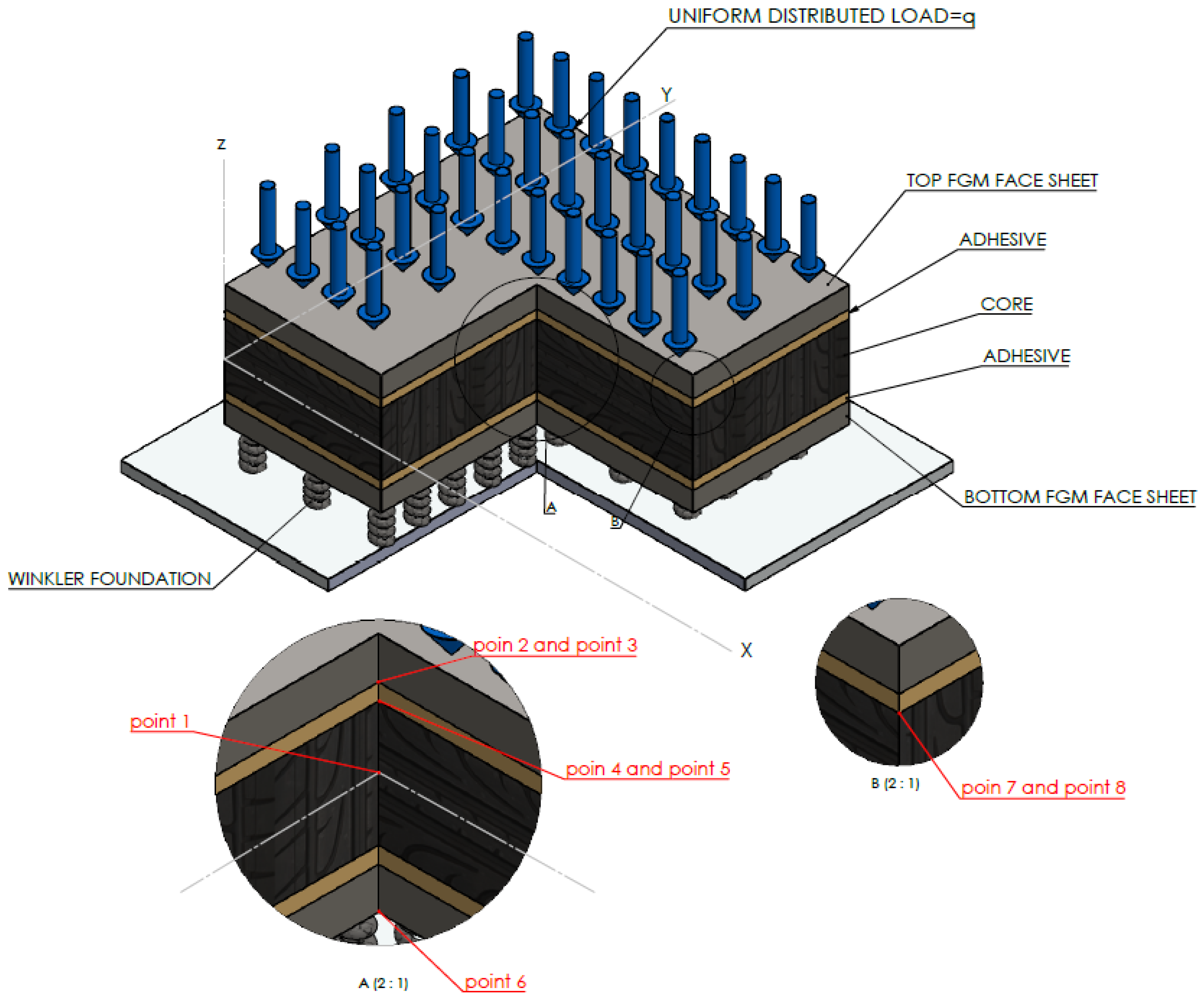
| Points Number | 1 | 2 | 3 | 4 | 5 | 6 | 7 | 8 |
|---|---|---|---|---|---|---|---|---|
| Location | Core | Face Sheet | Adhesive | Adhesive | Core | Face Sheet | Adhesive | Core |
| 0 |
| T °C | Method | ||||||||
|---|---|---|---|---|---|---|---|---|---|
| Point 1 | Point 2 | Point 3 | Point 4 | Point 5 | Point 6 | Point 7 | Point 8 | ||
| 23 | FE | −1.220 | −6.51 | −0.3838 | −0.36471 | −0.3647 | 39.103 | −0.8033 | −0.8057 |
| LW | −1.278 | −5.023 | −0.2732 | −0.2573 | −0.24082 | 38.9 | −1.0214 | −1.0214 | |
| %Difference | 4.8 | 22.8 | 28.8 | 29.4 | 34 | 6.5 | 27.2 | 26.8 | |
| 50 | FE | −1.3865 | −46.897 | −6.807 | −6.5249 | −2.368 | 105.445 | −1.0356 | −1.08477 |
| LW | −1.5159 | −45.125 | −5.930 | −5.918 | −1.236 | 70.2 | 0.4850 | 0.4850 | |
| %Difference | 9.3 | 5.1 | 12.9 | 9.3 | 47.8 | 33.4 | 53.2 | 55.3 | |
| 75 | FE | −1.4460 | −83.720 | −11.483 | −11 | −3.939 | 159.372 | −1.2323 | −1.3109 |
| LW | −1.602 | −82.50 | −10.018 | −10.013 | −2.017 | 97.93 | 1.604 | 1.604 | |
| %Difference | 10.8 | 1.5 | 12.7 | 9 | 48.8 | 38.5 | 30.2 | 22.3 | |
| 100 | FE | −1.538 | −119.45 | −15.01 | −14.387 | −5.0378 | 209.8 | −1.3446 | −1.4836 |
| LW | −1.7322 | −120 | −13.159 | −13.158 | −2.538 | 124.89 | 2.390 | 2.390 | |
| %Difference | 12.6 | 0.5 | 12.3 | 8.5 | 49.6 | 40.5 | 77.7 | 61.1 | |
| Kw (N/M2) | Method | ||||||||
|---|---|---|---|---|---|---|---|---|---|
| Point 1 | Point 2 | Point 3 | Point 4 | Point 5 | Point 6 | Point 7 | Point 8 | ||
| 0 | FE | −6.930 | −72.936 | −8.239 | −7.878 | −3.466 | 286.13 | −4.191 | −4.243 |
| LW | −7.580 | −64.47 | −6.898 | −6.817 | −1.869 | 229.1 | −3.581 | −3.581 | |
| %Difference | 9.4 | 11.6 | 16.3 | 13.5 | 46.1 | 19.9 | 14.6 | 15.6 | |
| 108 | FE | −6.329 | −70.06 | −8.108 | −7.756 | −3.382 | 265.86 | −3.915 | −3.967 |
| LW | −6.849 | −62.18 | −6.784 | −6.712 | −1.795 | 208.84 | −3.292 | −3.292 | |
| %Difference | 8.2 | 11.2 | 16.1 | 13.5 | 41.5 | 21.5 | 15.9 | 17 | |
| 109 | FE | −3.505 | −56.842 | −7.489 | −7.181 | −2.987 | 170.94 | −2.597 | −2.646 |
| LW | −3.588 | −51.942 | −6.271 | −6.240 | −1.462 | 119.25 | −1.896 | −1.896 | |
| %Difference | 2.4 | 8.1 | 17 | 13.1 | 51.1 | 30.2 | 27 | 28.3 | |
| n | Method | (m) | |||||||
|---|---|---|---|---|---|---|---|---|---|
| Point 1 | Point 2 | Point 3 | Point 4 | Point 5 | Point 6 | Point 7 | Point 8 | ||
| 0.5 | FE | −6.239 | −88.545 | −8.185 | −7.831 | −3.439 | 233.27 | −3.853 | −3.923 |
| LW | −7.014 | −63.25 | −6.838 | −6.770 | −1.836 | 180.07 | −3.206 | −3.206 | |
| %Difference | 12.4 | 28.6 | 16.5 | 13.5 | 46.6 | 22.5 | 16.6 | 18.1 | |
| 1 | FE | −6.930 | −72.936 | −8.239 | −7.878 | −3.466 | 286.13 | −4.191 | −4.243 |
| LW | −7.580 | −64.47 | −6.898 | −6.817 | −1.869 | 229.1 | −3.581 | −3.581 | |
| %Difference | 9.4 | 11.6 | 16.3 | 15.6 | 46.1 | 19.9 | 14.6 | 15.6 | |
| 2 | FE | −8.057 | −73.345 | −8.418 | −8.048 | −3.554 | 357.55 | −4.469 | −4.510 |
| LW | −8.536 | −68.337 | −7.091 | −6.99 | −1.991 | 299.2 | −3.97 | −3.97 | |
| %Difference | 5.9 | 6.8 | 15.7 | 13.1 | 44 | 16.3 | 11.2 | 10 | |
| Method | (m) | ||||||||
|---|---|---|---|---|---|---|---|---|---|
| Point 1 | Point 2 | Point 3 | Point 4 | Point 5 | Point 6 | Point 7 | Point 8 | ||
| 10 | FE | −0.19316 | −67.758 | −11.398 | −10.272 | −3.849 | 91.718 | −2.5096 | −2.4489 |
| LW | −0.26121 | −78.487 | −9.838 | −9.845 | −1.845 | 70.338 | 2.739 | 2.739 | |
| %Difference | 35.2 | 15.8 | 13.7 | 4.2 | 50.7 | 23.3 | 9.1 | 10.6 | |
| 20 | FE | −1.4460 | −83.720 | −11.483 | −11 | −3.939 | 159.372 | −1.2323 | −1.3109 |
| LW | −1.602 | −82.50 | −10.018 | −10.013 | −2.017 | 97.93 | 1.604 | 1.604 | |
| %Difference | 10.8 | 1.5 | 12.7 | 9 | 48.8 | 38.5 | 30.2 | 22.3 | |
| 30 | FE | −5.601 | −94.76 | −11.677 | −11.325 | −3.979 | 219.16 | −1.1714 | −1.2947 |
| LW | −5.566 | −89.38 | −10.327 | −10.302 | −2.222 | 144.640 | −0.48 | −0.48 | |
| %Difference | 1.1 | 5.7 | 11.6 | 9 | 44.2 | 34 | 50.5 | 62.9 | |
, h (mm) | Method | (m) | |||||||
|---|---|---|---|---|---|---|---|---|---|
| Point 1 | Point 2 | Point 3 | Point 4 | Point 5 | Point 6 | Point 7 | Point 8 | ||
| 0.1 12 | FE | −1.446 | −83.720 | −11.483 | −11 | −3.939 | 159.37 | −1.2323 | −1.3109 |
| LW | −1.602 | −82.50 | −10.018 | −10.013 | −2.017 | 97.93 | 1.604 | 1.604 | |
| %Difference | 10.8 | 1.5 | 12.7 | 9 | 48.8 | 38.5 | 30.2 | 22.3 | |
| 0.15 13.2 | FE | −1.010 | −75.319 | −11.604 | −11.063 | −4.296 | 127.47 | −1.381 | −1.3489 |
| LW | −1.184 | −80.47 | −9.927 | −9.926 | −1.955 | 83.19 | 1.635 | 1.635 | |
| %Difference | 17.3 | 6.8 | 14.4 | 10.3 | 54.5 | 34.7 | 18.4 | 13.6 | |
| 0.2 14.2 | FE | −0.77110 | −69.78 | −11.683 | −11.119 | −4.544 | 108.64 | −1.4667 | −1.5206 |
| LW | −0.9424 | −79.48 | −9.882 | −9.884 | −1.925 | 76.03 | 1.621 | 1.621 | |
| %Difference | 22.2 | 13.9 | 15.4 | 11.1 | 57.6 | 30 | 10.5 | 6.6 | |
, h (mm) | Method | (m) | |||||||
|---|---|---|---|---|---|---|---|---|---|
| Point 1 | Point 2 | Point 3 | Point 4 | Point 5 | Point 6 | Point 7 | Point 8 | ||
| 0.1 12 | FE | −6.930 | −72.936 | −8.239 | −7.878 | −3.466 | 286.13 | −4.191 | −4.243 |
| LW | −7.580 | −64.47 | −68.98 | −6.817 | −1.869 | 229.1 | −3.581 | −3.581 | |
| %Difference | 9.4 | 11.6 | 16.3 | 13.5 | 46.1 | 19.9 | 14.5 | 15.6 | |
| 0.15 13.2 | FE | −4.804 | −55.362 | −7.682 | −7.318 | −3.247 | 203.71 | −3.925 | −3.962 |
| LW | −5.554 | −52.20 | −6.283 | −6.236 | −1.459 | 164.6 | −3.115 | −3.115 | |
| %Difference | 15.6 | 5.8 | 18.2 | 14.8 | 55 | 19.2 | 20.6 | 21.4 | |
| 0.2 14.4 | FE | −3.650 | −45.84 | −7.409 | −7.047 | −3.173 | 160.31 | −3.670 | −3.698 |
| LW | −4.395 | −46.07 | −5.976 | −5.944 | −1.254 | 132.82 | −2.708 | −2.708 | |
| %Difference | 20.4 | 0.5 | 19.3 | 14.9 | 60.5 | 17.1 | 26.2 | 26.8 | |
Publisher’s Note: MDPI stays neutral with regard to jurisdictional claims in published maps and institutional affiliations. |
© 2022 by the authors. Licensee MDPI, Basel, Switzerland. This article is an open access article distributed under the terms and conditions of the Creative Commons Attribution (CC BY) license (https://creativecommons.org/licenses/by/4.0/).
Share and Cite
Kardooni, M.R.; Shishesaz, M.; Mosalmani, R. Three-Dimensional Thermo-Mechanical Elastic Analysis of Functionally Graded Five Layers Composite Sandwich Plate on Winkler Foundations. J. Compos. Sci. 2022, 6, 372. https://doi.org/10.3390/jcs6120372
Kardooni MR, Shishesaz M, Mosalmani R. Three-Dimensional Thermo-Mechanical Elastic Analysis of Functionally Graded Five Layers Composite Sandwich Plate on Winkler Foundations. Journal of Composites Science. 2022; 6(12):372. https://doi.org/10.3390/jcs6120372
Chicago/Turabian StyleKardooni, Mohammad Reza, Mohammad Shishesaz, and Reza Mosalmani. 2022. "Three-Dimensional Thermo-Mechanical Elastic Analysis of Functionally Graded Five Layers Composite Sandwich Plate on Winkler Foundations" Journal of Composites Science 6, no. 12: 372. https://doi.org/10.3390/jcs6120372