
Energy Direction in Ultrasonic Impregnation of Continuous Fiber-Reinforced Thermoplastics


Institute of Polymer Technology (LKT), Friedrich-Alexander Universität Erlangen-Nürnberg, Am Weichselgarten 9, 91058 Erlangen-Tennenlohe, Germany
*
Author to whom correspondence should be addressed.
J. Compos. Sci. 2021, 5(9), 239; https://doi.org/10.3390/jcs5090239
Submission received: 18 August 2021
/
Revised: 31 August 2021
/
Accepted: 2 September 2021
/
Published: 7 September 2021
Abstract
:As a new and innovative processing method for fabrication for fiber-reinforced thermoplastic composites (CFRTs), the feasibility of ultrasonic welding technology was proven in several studies. This method offers potential for the direct manufacturing of CFRT–metal structures via embedded pin structures. Despite the previous studies, a deeper understanding of the process of energy input and whether fibers work as energy directors and consequently can, in combination with chosen processing parameters, influence the consolidation quality of the CFRTs, is still unknown. Consequently, the aim of this work is to establish a deeper process understanding of the ultrasonic direct impregnation of fiber-reinforced thermoplastics with an emphasis on the fiber’s function as energy directors. Based on the generated insights, a better assessment of the feasibility of direct, hybrid part manufacturing is possible. The produced samples were primarily evaluated by optical and mechanical test methods. It is demonstrated that with higher welding time and amplitude, a better consolidation quality can be achieved and that independent of the process parameters chosen in this study, no significant fiber breakage occurs. This is interpreted as a sign of a gentle impregnation process. Furthermore, based on the examination of single roving and 5-layer set-ups, it is shown that the glass fibers function as energy directors and can influence the transformation of sonic energy into thermal energy. In comparison to industrially available CFRT material, the mechanical properties are weaker, but materials and processes offer potential for significant improvement. Based on these findings, proposals for a direct impregnation and joining process are made.
1. Introduction
In times of increasing global warming, the reduction of CO2 emissions is a major societal challenge. One approach for emission reduction in the transport sector is the weight reduction of transportation devices. The substitution of classic engineering materials such as steel or aluminum with lightweight fiber-reinforced composites such as continuous fiber reinforced plastics (CFRPs) is one possible way to achieve this goal [1], although the recyclability of many CFRP materials is currently unsatisfactory and is a subject of ongoing research [2].
For several applications, short or long fiber reinforced plastics are sufficient since higher moduli can be reliably reached with lower fiber lengths [3,4]. However, applications that require high strength and impact properties, such as those in the transportation sector, necessitate the highest possible fiber length, as only then the maximum weight-specific impact properties can be achieved [5,6]. In comparison to thermoset-based CFRPs, continuous fiber-reinforced thermoplastics (CFRTs) typically have several advantages: a higher impact strength, simple storage possibilities without refrigeration, and practically unlimited shelf time, as well as short cycle times [7]. CFRT parts are typically manufactured via hot press processes from semi-finished products such as pre-consolidated sheets or comingled yarn systems.
Despite the favorable properties of CFRTs, these materials reach their limitations in applications requiring elevated temperatures above the melting temperature (semi-crystalline matrix) or the glass temperature (amorphous matrix), as well as in high-abrasive-wear and/or aggressive environments where environmental degradation can also have a negative impact on a CFRT component. The use of hybrid CFRT–metal parts is one approach to overcome these limitations. In the field of CFRP–metal hybrid joining, a large variety of form-fit joints has been developed, and the corresponding joint development is oftentimes an integral part of the part development itself [8]. A rather unconditional way of joining, due to only requiring two parallel surface segments, is the usage of either adhesives or pins or bolts.
In contrast to bolts, pins are introduced into the material during the forming or a bonding process while the matrix is in a molten or viscous state. For thermosets, the pins are inserted prior to curing. After curing, the resulting joint is a combination of adhesive joining, due to matrix–metal interaction, and a form fit [9,10]. For thermoplastics, the pins are inserted into the composite heated above the polymer melting temperature. The hybrid part is then cooled down resulting in primarily a form fit, due to the typically insufficient chemical interaction of polymer and metal [11,12].
The usage of pins can yield comparatively high bonding strengths. Compared to only adhesively joint samples, an increase of the maximum force of 650% could be achieved for thermosets in [13]. Pin joints often also do not cause fiber separation or breakage, which can occur when preparing parts for the usage of bolts or riveted joints. Instead, the fibers are re-aligned around the corresponding pins [14]. This leads to promising mechanical properties of the joints [15]. Normalized to one single pin, lap shear samples were tested to maximum transmitted forces between 118 N [16] and 335 N [17].
However, for CFRTs, the usage of pins results in a comparably long process chain, comprising initial composite sheet manufacturing, subsequent part manufacturing, and finally part joining. Hence, alternative procedures, reducing the overall complexity of this process chain, would be favorable. This could help in reducing both the combined processing costs and the associated environmental impact, as currently, the same composite material needs to be heated thrice to the necessary forming temperature in the standard process chain.
One possible approach to integrate impregnation and joining into a single process step is the use of ultrasonic impregnation. Here, ultrasonic vibration is used to melt the thermoplastic matrix of a stack of matrix sheets and dry fiber layers, allowing for a subsequent simultaneous pressure-driven pin insertion and fiber impregnation. The approach has been successfully demonstrated for stacks of matrix films and dry fibers without pins by Gomer [18]. Other studies investigating the ultrasonic impregnation of CFRTs investigate continuous [19,20] and discontinuous processes [19]. Despite wide experimental and numerical investigations of different process parameters and material combinations, a deeper analysis of the underlying mechanisms has yet to be conducted, before it can be safely applied to more complex structures featuring pins for direct joining. Specifically, the question of how energy direction occurs in such a process, and consequently how to tailor it to the process, is still unclear. In order to be able to design a combined direct impregnation and joining process, a complete understanding of the direct impregnation process on its own needs to be secured first. With this background, this study aims at creating a deeper understanding of the ultrasonic direct impregnation process, prospectively aiming at a combined one-step impregnation and joining process.
2. Experimental
2.1. Used Materials
In this investigation, one thermoplastic polymer and two different types of dry non-crimp glass fiber fabrics were used. The thermoplastic polymer used in this work was a polypropylene (PP) type BJ100HP (Borealis AG, Vienna, Austria), which is specifically designed for fiber-reinforced composite applications requiring thorough fiber impregnation. The polymer was used as film material with three different thicknesses of 500 ± 25 µm, 700 ± 25 µm, and 1000 ± 25 µm.
The first non-crimp E-glass fiber fabric (referred to as Type 1) was a KN G 300.1 (Glasseiden GmbH, Oschatz, Germany) with an areal weight of 292 g/m2, silane sizing, and a polyester sewing thread (areal weight 8 g/m2). This non-crimp fabric consisted of two layers of continuous parallel fibers each. The first layer had an areal weight of 164 g/m2 and the second layer, oriented perpendicular (90°) to the first, featured an areal weight of 120 g/m2. Singular rovings were extracted from this fabric in order to conduct impregnation experiments with single rovings, which allow for a more detailed investigation of the energy direction in ultrasonic impregnation.
The second non-crimp E-glass fiber fabric (referred to as Type 2) was a B-E-604 g/m2-1270 (SAERTEX GmbH & Co. KG, Saerbeck, Germany), with an areal weight of 604 g/m2, silane sizing, and an aramid sewing thread (areal weight 32 g/m2). This non-crimp fabric consisted of two layers of continuous parallel fibers each. The first layer featured an areal weight of 260 g/m2 and the second layer, oriented at 80° in relation to the first one, had an areal weight of 312 g/m2.
2.2. Ultrasonic Impregnation
All experiments in this study were conducted with an ultrasonic welding machine of the type HiQ DIALOG 6200 Speed Control (Herrmann Ultraschall GmbH & Co. KG, Karlsbad, Germany). The device has a nominal operating frequency of 20,000 Hz, whereby the actual operating frequency can be varied from 19,500 to 22,000 Hz. It features a generator with a nominal power output of 6200 W, and the used titanium horn has a contact area of 60 × 60 mm2. The welding force can be adjusted between 30 and 2490 N.
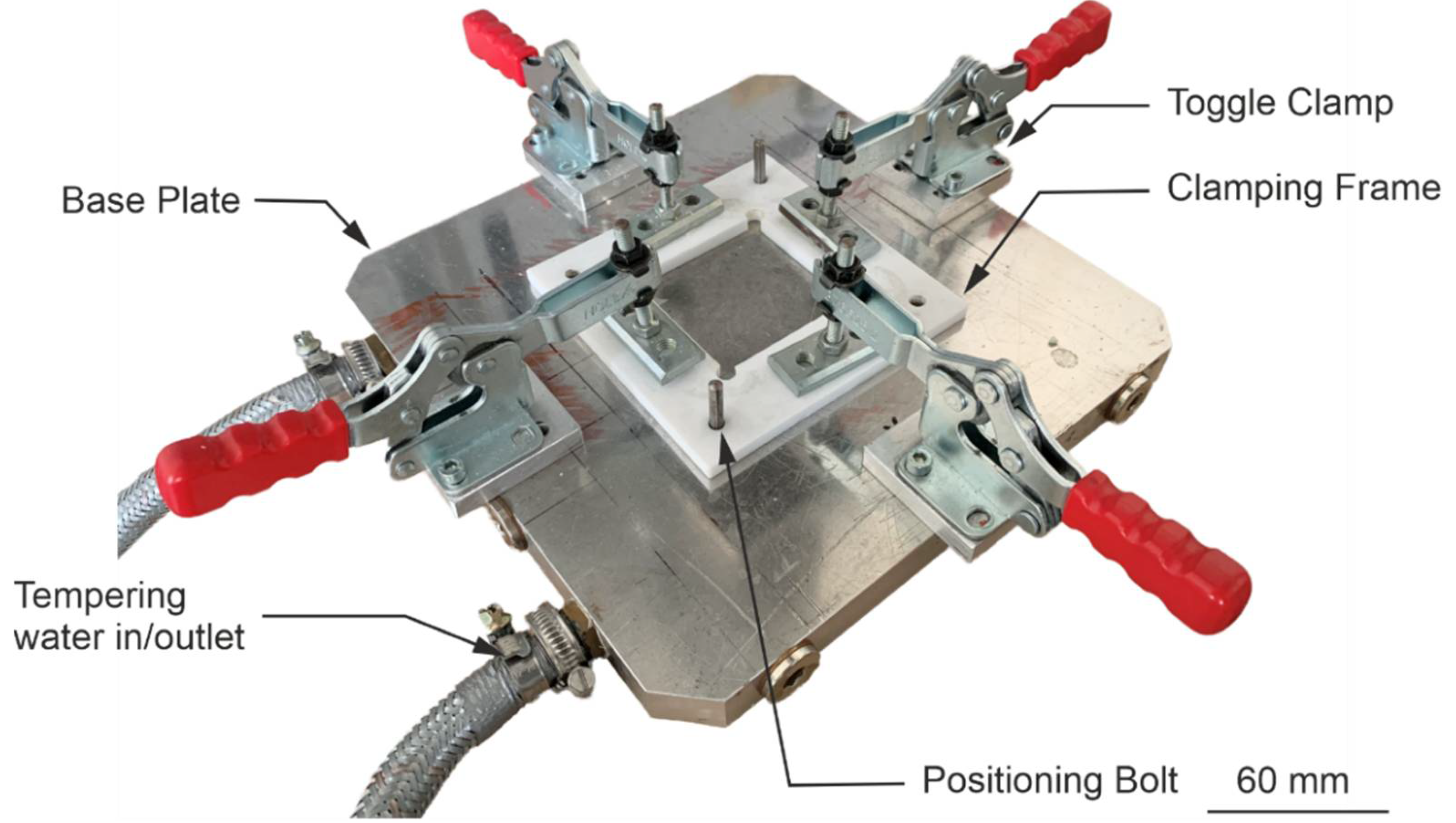
The ultrasonic impregnation process is as follows: First, the films and non-crimp fabric layers were cut to 140 × 140 mm2, and each was stacked as an alternating layer below the ultrasonic horn. In order to allow for good repeatability and to keep the layers in place during the impregnation process, a custom polytetrafluorethylene (PTFE) clamping frame was used. The frame was positioned via positioning bolts and clamped with four toggle clamps over the polymer/fabric stack. The clamping frame has outer dimensions of 130 × 130 mm2 and an inner opening of 65 × 65 mm2, slightly larger than the horn. This difference in size allowed excess matrix material to flow in between frame and horn. Furthermore, it was possible to heat the base plate of the clamp via a water-based tempering device. Figure 1 displays the used clamping frame.
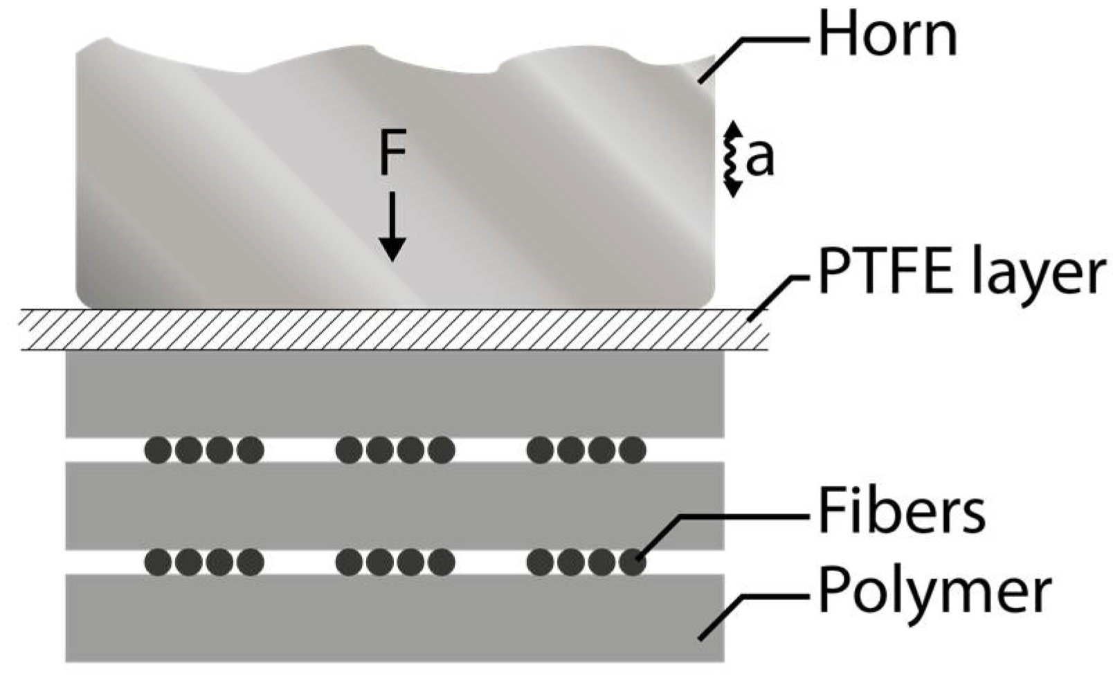
In order to avoid any adhesion between horn and molten matrix polymer, a PTFE film was placed between the horn and the polymer/fiber stacks. Figure 2 illustrates the general setup used for the impregnation process. Three different stacking setups were investigated: single glass roving (polymer–roving–polymer), three layers (polymer–fabric–polymer), and five layers (polymer–fabric–polymer–fabric–polymer) as exemplary displayed in Figure 2. In the following, the layers are counted from top to bottom. Consequently, the layer closest to the horn is referred to as layer 1.
Since materials’ energy transfer property is directly proportional to materials’ stiffness or storage modulus, which, in this case, was determined by the combination of the polymer/fabric stack, at a given operating frequency, it was necessary to adjust the welding parameters for different setups even if the matrix material of the stack was identical [21]. In pre-trials, different parameter combinations were tested in order to determine viable processing windows in dependency of the chosen setup. Based on these pre-trials, variations of the process parameters welding time and amplitude were made and investigated in the course of this study. Following Table 1 summarizes the used experimental setups and impregnation parameters.
It has to be noted that the welding time for the 5-layer setup was defined dependently on the chosen amplitude; as verified in pre-trials, a lower amplitude required longer welding times. This can be explained by the following equation, which describes the ultrasonic intensity as a function of the speed of sound in the material, material’s density , the frequency , and the amplitude [21].
Consequently, the investigated welding times for an amplitude of 30 µm are 11, 12, and 13 s, whereas the welding times with an amplitude of 32 µm are 9, 10, and 11 s.
2.3. Impregnation Quality
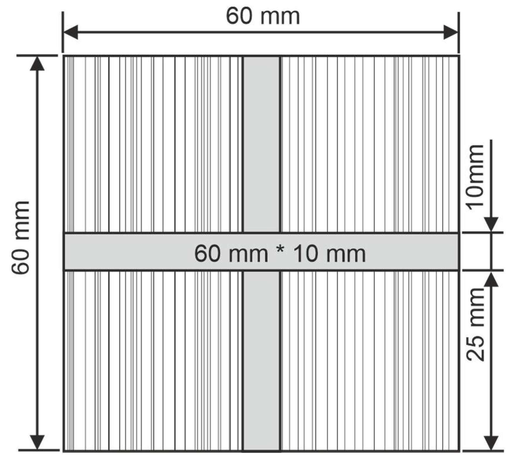
The impregnation quality was analyzed with reflected light/bright field microscopy with a microscope of the type AxioImagerM2 (Carl Zeiss Microscopy GmbH, Jena, Germany). The investigated areas are shown in Figure 3. In the first step, strips with a size of 10 × 60 mm2 were cut from the center of the laminate. In a second step, slices were cut from the center of the strips and embedded in an epoxy resin in order to allow for subsequent preparation and grinding. Due to the sample preparation sequence, the slices hence reflect the quality of the part close to the absolute center in either preparation direction.
The embedded samples were ground with grit paper of increasing grades, up to grade 4000. It has to be noted that a final polishing process was not conducted because the characteristic scratches in the embedding resin allow for an easier differentiation of the resin and the PP matrix material in the sample. Specifically, large air pockets in the samples could be infused with resin in the embedding process and would otherwise be nigh impossible to identify.
Each microscopic sample was observed in detail. A special focus was placed on potential inhomogeneities such as air pockets and thermally damaged areas of the matrix. Both can be interpreted as unsatisfactory impregnation quality. To facilitate the evaluation of the microscopy images, their contrast and brightness were adjusted using the software Adobe Photoshop (version 13.0; Adobe Inc., San José, CA, USA).
2.4. Fiber Breakage
The fiber length has a significant influence on the mechanical properties of a part. Although the stiffness reaches a maximum at fiber lengths of approximately 1 mm [3,4], strength and impact properties improve with increasing fiber lengths [5,6]. Consequently, it is favorable to avoid fiber breakage during the impregnation process, as this would lead to a reduced fiber length and diminished strength and impact properties. In order to investigate if the ultra-sonic impregnation process leads to a significant fiber breakage, samples from the central area of 3- and 5-layer setups were extracted after the impregnation process. These samples were incinerated, and the residual fibers were cleaned and examined under the microscope. The created images were qualitatively observed in detail and searched for broken fibers.
2.5. Mechanical Characterization
In order to assess the mechanical performance of samples produced via ultrasonic impregnation, tensile tests were conducted. Thereby samples were cut with a water-cooled saw from the middle of the original 60 × 60 mm2 samples with the dimension 16 × 60 mm2 and subsequently tested based on DIN EN ISO 527. The mechanical testing was performed on a universal testing machine Z100 (Zwick & Roell GmbH & Co. KG, Ulm, Germany). The strength was tested with a testing speed of 1.0 mm/s. The clamping free length is 23 mm. Both the layer setups (8 tested samples per setting) and 5-layer setups (10 tested samples per setting) were tested.
3. Results and Discussion
3.1. Impregnation Quality
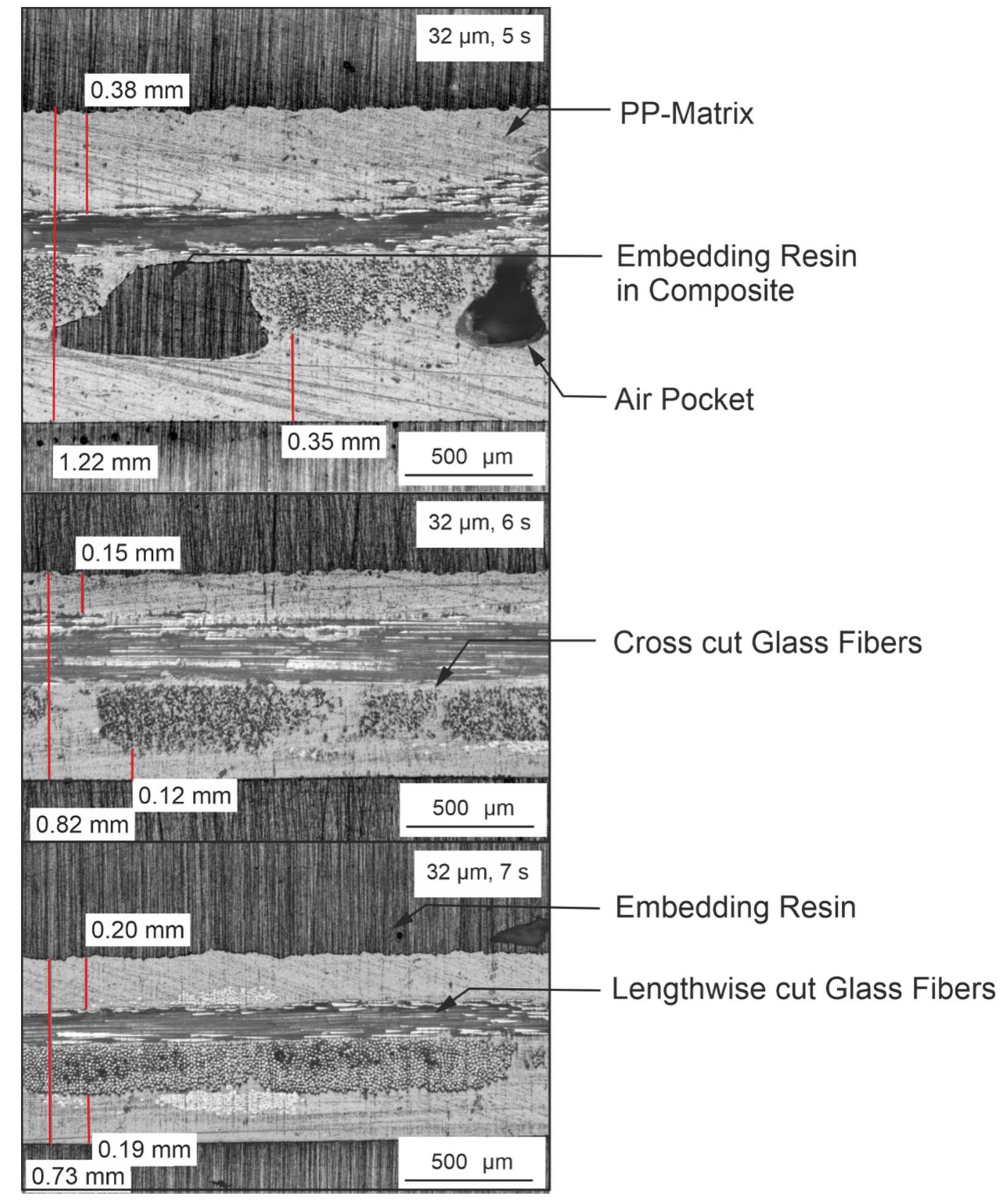
When investigating the microscopic images of the three-layer setup, a clear difference between the different welding times can be seen. Samples manufactured with a welding time of 5 s show partial air pockets, which can be interpreted as a sign of insufficient impregnation quality. Two different explanations for this behavior are possible: First, the introduced energy is not sufficient to melt the matrix to a significant degree, meaning that the melt viscosity is low enough to completely impregnate the non-crimp fabric. Second, it is possible that the time in which the matrix is in a molten state is not sufficient to reach a complete impregnation. Figure 4 shows exemplary images of samples with a three-layer setup and welding times of 5, 6, and 7 s.
In addition to the reduced amount of air pockets, a reduction in sample thickness can be observed for increasing welding times. This can be explained by the increased displaced volume of air, which results in a reduced thickness, as well as matrix material being pushed out on the sides of the ultrasonic horn and matrix impregnating into the fiber roving. Furthermore, the thickness of the top and bottom polymer layers is comparable, independently of the chosen processing parameters.
3.2. Fiber Breakage
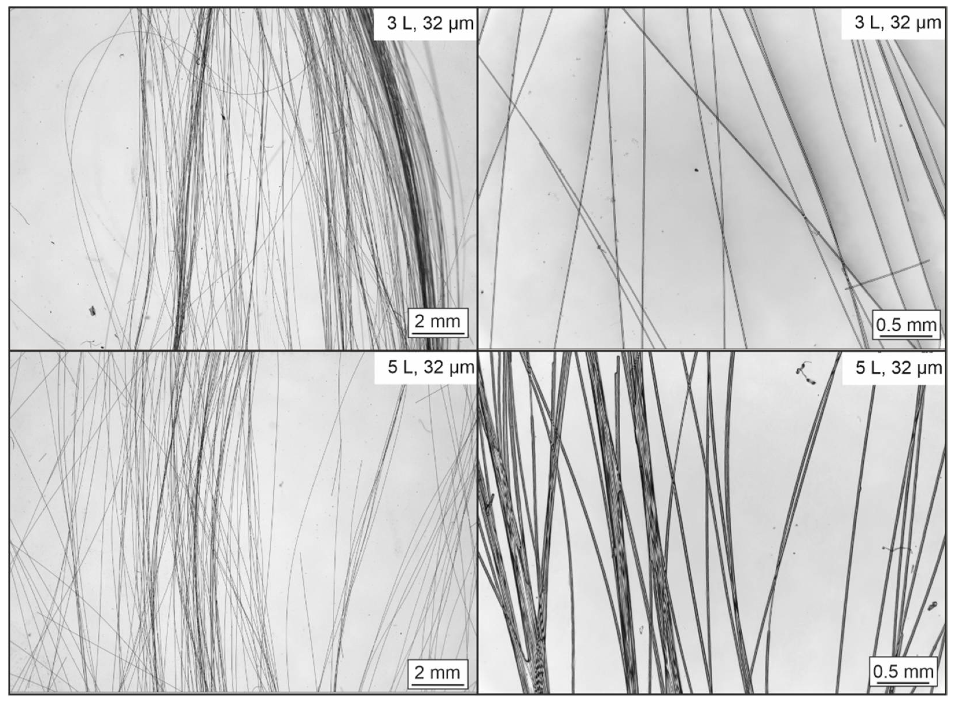
The microscopic examination of the separated glass fibers after the incineration and cleaning process reveals almost exclusively intact fibers. No significant fiber breakage can be seen in any of the investigated images. Figure 5 shows two exemplary images of a 3- and 5-layer setup, each with a magnification of 125% and 500%. Within the shown images, only minimal fiber breakage can be seen. However, it is possible the slight visible damage is caused during the sample preparation process and not during the actual impregnation process. There is no systematic difference visible between different sample setups and process parameters.
3.3. Evidence of Fiber Working as Energy Director
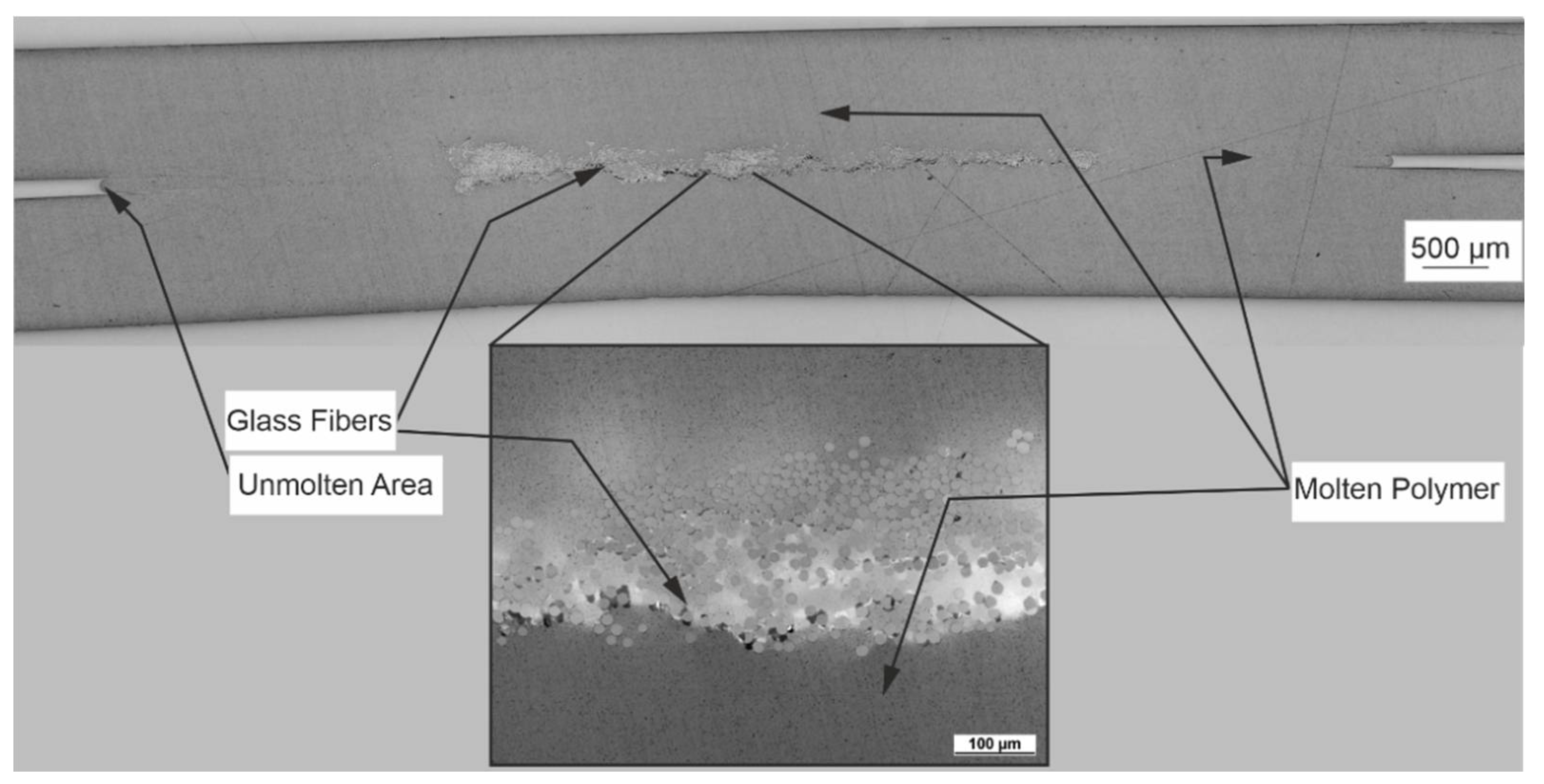
When investigating the light microscopy images of the single glass roving samples, it can be seen that a good macro- and micro impregnation can be achieved. Figure 6 shows an overview image and a detailed cross-sectional image perpendicular to the fiber orientation. It can be seen that close to the glass fibers, the polymer film is molten, and both films are welded together. When examining the detailed image, a good micro impregnation can be seen, with polymer impregnating deeply between the single filaments. At a distance of approximately five millimeters left and right from the glass fibers, the connection between the two polymer films can no longer be seen. An explanation for this could be that the fibers act as energy directors: the sonic energy induced by the welding process is almost exclusively converted to thermal energy in close proximity of the glass fibers. Due to the short welding time of only one second, thermal conduction does not lead to a significantly increased expansion of the thermal field. Hence, sufficient heating of the matrix above its melting temperature is only achieved close to the fibers.
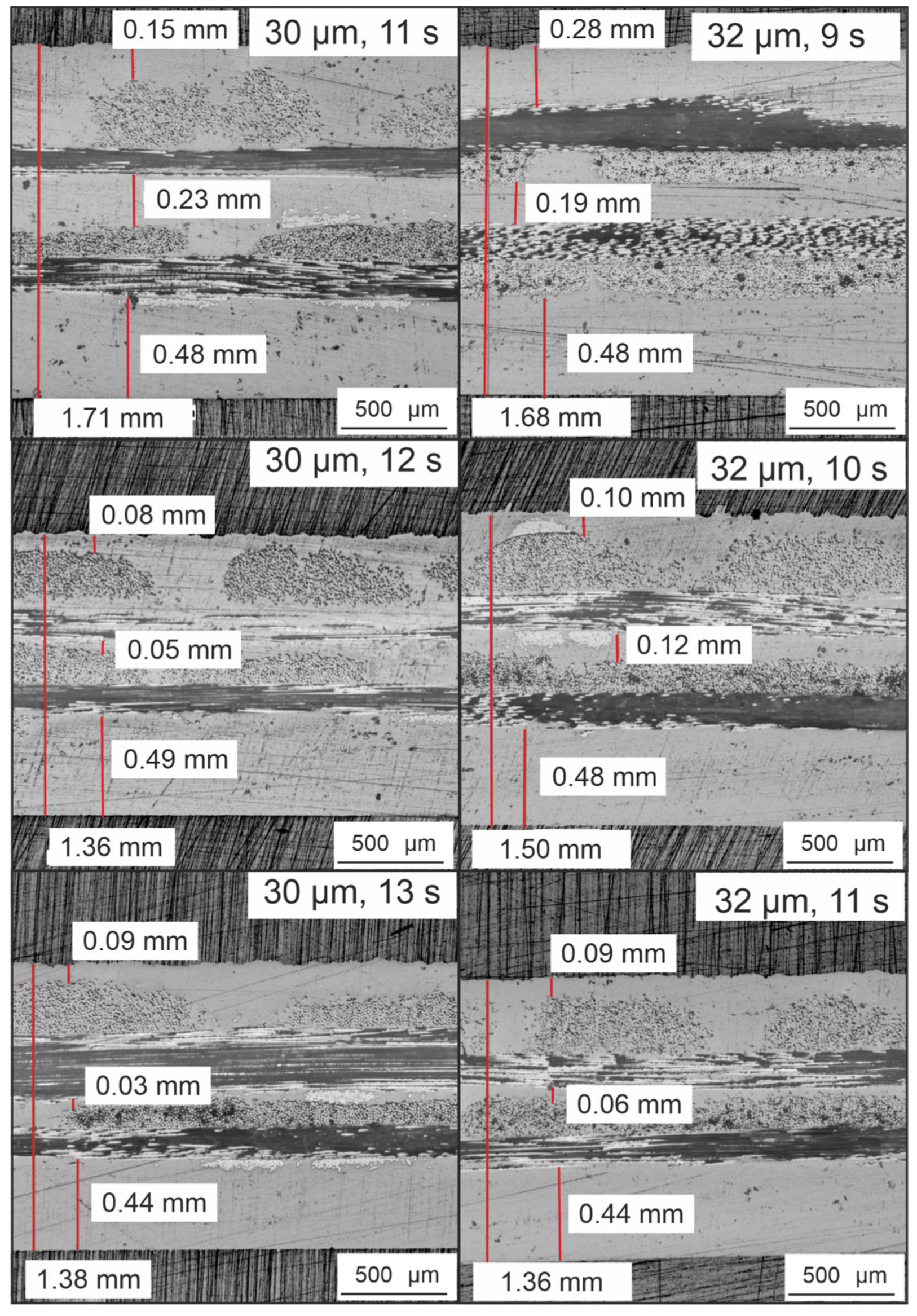
Figure 7 shows exemplary images of samples with a five-layer setup and welding times of 9 to 13 s and amplitudes of 30 and 32 µm. The samples were cut perpendicular to the first fiber layer, while samples cut in the opposite direction show very similar results. The focus of this investigation lied in the evaluation of the overall thickness of the composite and the thickness of the three individual polymer layers. It can be clearly seen that the overall thickness reduces with longer welding time, as already seen for the three-layer setup. The samples manufactured with an amplitude of 30 µm and welding time of 11 s have a thickness of 1.71 mm, while with a welding time of 13 s, the thickness reduces to 1.38 mm. It is noticeable that polymer layer 3 remains at a similar thickness for all welding times, which is close to the initial thickness of the polymer film before impregnation, which can be seen as a sign that this layer remains at, or at least close to, solid-state during the impregnation process. In contrast to this finding, layers 1 and 2 are significantly thinner and also reduce in thickness with increasing welding time. This reduction observed in layers 1 and 2 significantly contributes to the reduced overall thickness, in conjunction with slight compaction of the fiber rovings. Samples with an amplitude of 32 µm show very similar results, with a decreasing overall thickness and increasing welding time, while layer 3 remains at almost the same thickness.
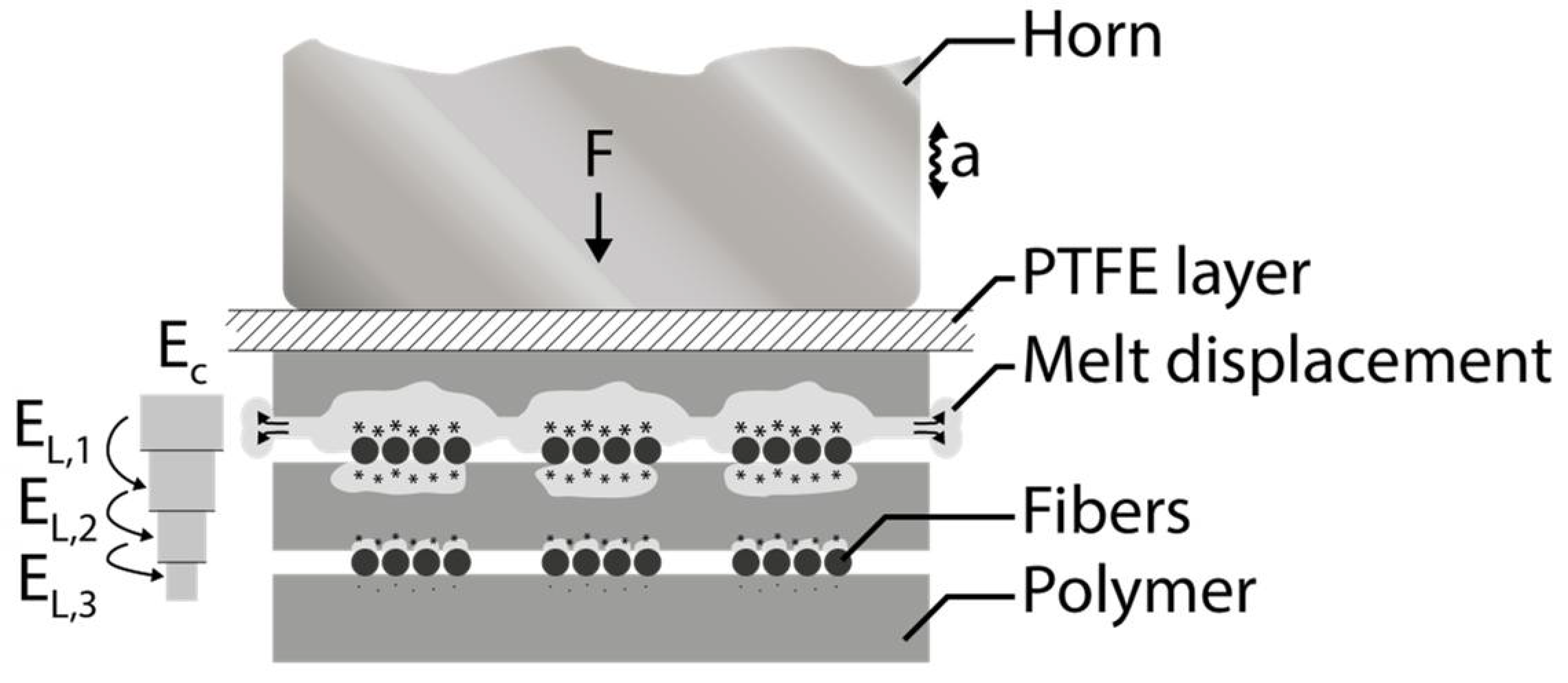
An explanation for this phenomenon can be found in the fibers working as energy directors: As the ultrasonic waves travel through the fiber/polymer stack from top to bottom, the kinetic energy is transformed into heat at the first layer of fibers with which they come in contact. This is the fiber layer between layers 1 and 2, which consequently are molten, impregnating the fiber layers, and if there is a surplus, they are pressed out between the clamping frame and ultrasound horn. Figure 8 summarizes the described model of fibers working as energy directors and reduced mechanic energy and increased thermal energy with increasing distance from the horn.
In comparison to industrially available CFRT materials, which often have fiber volume content of approx. 45% [22] the achieved fiber volume contents in this study are lower with a fiber volume fraction, ranging from 17.80 vol.% for a three-layer set up with 30 µm amplitude and 5 s welding time to 32.4 vol.% for a five-layer set up with 32 µm amplitude and 11 s welding time. Table 2 gives an overview of calculated fiber volume content based on the used glass fiber fabrics and measured laminate thickness. For these calculations, three individual measurements were used, and the average was calculated.
As a result of the lower fiber volume content, it can be expected that the mechanical properties of the samples presented in this study fall behind industrially available CFRT materials [23]. Therefore, in future investigations, it is the main goal to reach higher fiber volume contents than shown in this study. However, the high matrix content is chosen deliberately, in order to see the effects in the ultrasonic impregnation process, especially of the fibers working as energy directors, more clearly.
3.4. Mechanical Characterization
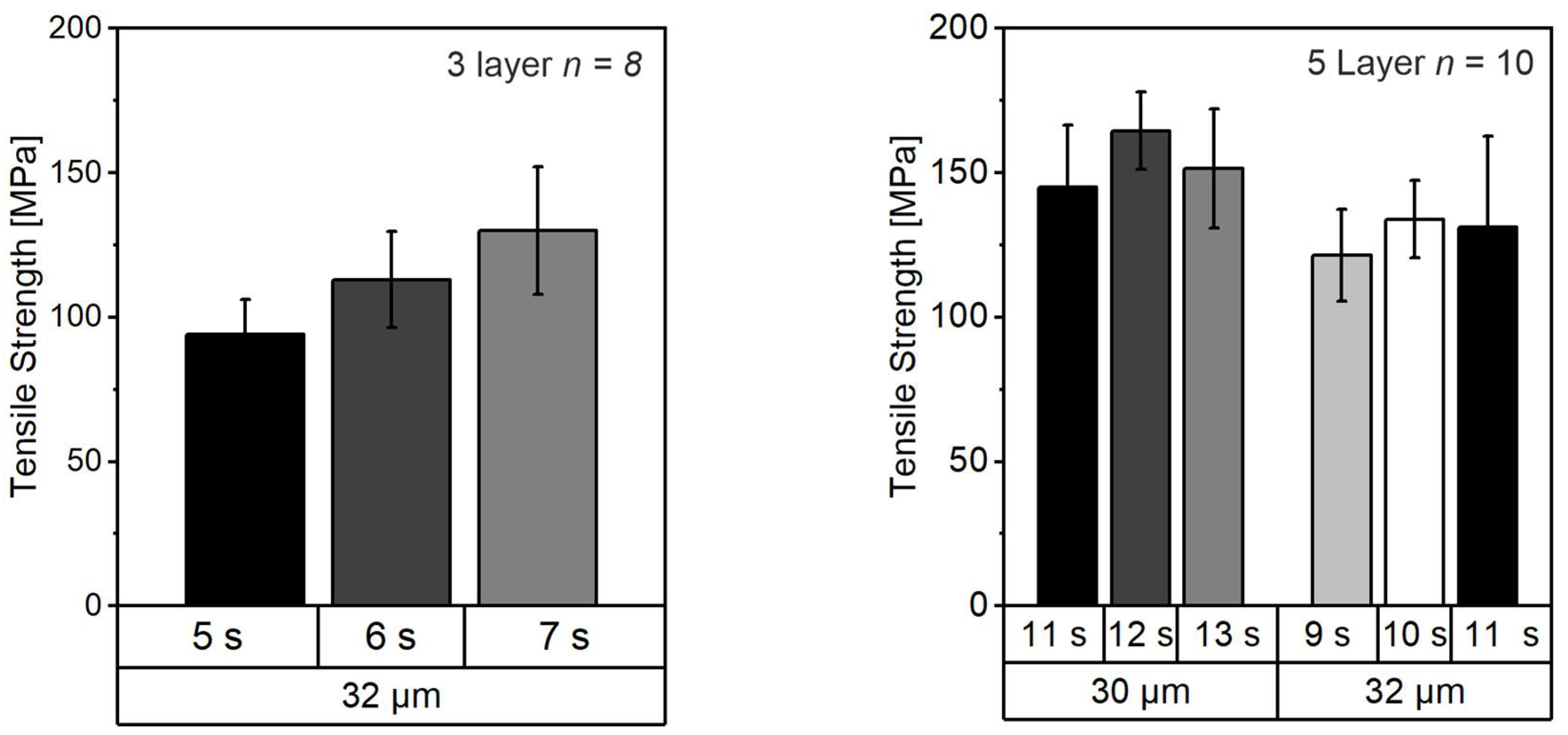
When investigating the tensile strength of the samples, results reveal that a dependency on the welding parameters is present. Figure 9 summarizes the results of the tensile tests conducted in the scope of this study.
The measured tensile strength ranges from 94 ± 12.2 MPa for a three-layer sample manufactured with an amplitude of 32 µm and a welding time of 5 s up to 165 ± 13.4 MPa for a five-layer sample manufactured with an amplitude of 30 µm and a welding time of 12 s. When comparing these values with Table 2, it is noticeable that the best- and worst-performing samples also feature the highest and lowest fiber volume contents, which confirms the previously made assumption that a low fiber content leads to worse mechanical properties.
Generally, it can be concluded that the tensile strength is below industrial standard materials. For example, a Tepex Dynalite 104 with a fiber volume content of 47 vol.% has a tensile strength of 430 MPa according to ISO 527-4/5, which is significantly above the values measured in this study [24].
The lower mechanical performance can be explained by several approaches. First, the fiber volume content reached in this study is significantly lower, with a maximum value of 32.21 vol.%.Typically, the strength of composite materials is directly related to the fiber content. Second, in the present study, fibers without specific sizing for polypropylene were used. Due to the low surface energy of PP, it is assumed that insufficient fiber–matrix bonding leads to reduced mechanical properties. Third, the fibers are not perfectly aligned with the applied force during mechanical testing since, on the one hand, a slight distortion of the fibers appears during the impregnation process due to matrix flow and, on the other hand, the used non-crimp fabrics with a 0°/80° orientation are not symmetrical, leading to unfavorable loading on the samples. Consequently, a non-crimp or woven fabric with a 0°/90° orientation and stronger fixation of the fiber architecture could be beneficial for the mechanical performance of the samples.
To summarize, the mechanic properties need to be improved in future studies. However, optimization of mechanical performance was not the primary focus of this study. It was planned to work with non-crimp fabrics featuring a sizing better suited for the utilized matrix system and to use 0°/90° or unidirectional fabrics. Furthermore, a process optimization needs to be performed to increase the fiber volume content and consequently mechanical properties.
4. Discussion
The investigation of the five-layer setting revealed the following findings: Depending on the chosen amplitude and welding time, the thickness of the resulting laminate differs. With increasing energy introduced into the laminate as a result of longer welding time or increased amplitude, the overall thickness of the laminate reduces. This can be explained by an increasing degree of impregnation of the fiber rovings, which consequently trapped air and matrix material being pushed out of the laminate stack. It can be seen that the polymer layer located furthest away from the horn remains at its original thickness. The acoustic energy is, to a high degree, transformed into thermal energy in all films in which they are in contact with the fiber layers. Subsequent layers only experience reduced acoustic energy exposition due to the high acoustic loss in each polymer layer. Consequently, only the middle and top polymer layers were heated to a significant degree and could impregnate into the fibers or be pushed out of the laminate, while the acoustic energy reaching the bottom layers was insufficient for significant heat development.
Transferring these findings to the manufacturing of multi-layer CFRT composites with high thicknesses, it is expected that difficulties arise in evenly heating the laminate. A similar problem statement could be found in [15], in which CFRT samples were heated from one side with infrared radiation. Complete heating over the melting point of the PP matrix without overheating the irradiated surface was difficult to achieve. Adjusting the bottommost tooling temperature can help in evening out the temperature distribution, but the total amount of suitable individual layers appears to be limited since, in the five-layer setup, the bottommost polymer film is already insufficiently heated to reach a molten state in larger sample areas.
Another point to take into account when designing suitable stacks for ultrasonic impregnation is the uneven polymer matrix relocation, with the top layer experiencing the highest amount of matrix relocation. For final parts featuring homogeneous layer distributions, it is advisable to tailor the polymer films to higher thicknesses, closer to the horn they are located in the process. With this method, the matrix relocation can be compensated, resulting in even-spaced layers.
The setups shown in this investigation feature relatively low fiber volume contents when compared to industrially available CFRT semi-finished products (e.g., Tepex Dynalite 104). This was chosen in order to be able to clearly show the effect of process parameters and fibers working as energy directors. In future investigations, it will be necessary to increase the fiber volume content in order to achieve compatible mechanical properties. As previously shown, the combination of material layering setup and process control allows for distinct tailoring of the part thicknesses and resulting fiber volume contents. While adjustments based on the individual material properties are necessary to cater to specific material combinations, the processing, as it is shown here, can be expected to be stable for any combination of high-stiffness reinforcing fiber and lower-stiffness polymer matrix. This allows for specifically tailored part production with a wide range of possible part properties. Due to the low fiber content, among other reasons, the mechanical performance is not satisfying yet and requires further research to be improved.
5. Conclusions
In the scope of this study, it could be shown that a successful ultrasonic impregnation of non-crimp glass fibers with polypropylene films is possible. Based on microscopic investigations of three-layer setups with different welding times, it could be shown that a sufficient amount of energy needs to be introduced into the laminate to achieve satisfactory impregnation. Consequently, the welding time is of high importance to a good impregnation quality without significant inhomogeneity, such as air pockets.
The function of the fibers as energy directors could be shown in two different settings. First, a single roving was impregnated with two layers of polymer films. Based on the limited area in close proximity of the glass fiber roving, where both polymer films were molten and consequently welded together, it could be seen that the mechanical energy of the ultrasonic vibration was only transformed into thermal energy in direct proximity to the glass fibers. Consequently, it is assumed that the fibers function as energy directors. These findings need to be set into relation to the individual material properties of fibers and matrices. In this case, high-stiffness fibers were used. While it can be assumed that other high-stiffness fibers such as boron fibers or carbon fibers show a comparable behavior regarding energy direction, additional research is necessary to clarify how the complete system reacts in conjunction with lower-stiffness fibers such as aramid or other polymeric fibers. In future studies, it is necessary to improve the process by means of increased fiber volume content as well as improved mechanical properties.
Based on the presented findings, direct manufacturing of CFRT–metal parts joined via metallic pins appears possible. In further investigations, it will be necessary to investigate if and how metallic pins influence the energy input into the laminate, and how it influences the impregnation process. Potentially, introduced metallic pins improve the heating through samples’ thickness due to the typically higher thermal conductivity of metals in comparison to polymers and glass fibers, facilitating the process for otherwise limited processing of high-layer-count composites.
Author Contributions
Conceptualization, J.P., M.W. and T.M.; methodology J.P., M.W. and T.M.; formal analysis, J.P., M.W. and T.M.; investigation, J.P. and M.W.; resources, D.D.; writing—original draft preparation, J.P.; writing—review and editing, M.W., T.M. and D.D.; visualization, T.M.; supervision, D.D.; project administration, D.D.; funding acquisition, D.D. All authors have read and agreed to the published version of the manuscript.
Funding
Funded by the Deutsche Forschungsgemeinschaft (DFG, German Research Foundation)—TRR 285—Project-ID 418701707.
Institutional Review Board Statement
Not applicable.
Informed Consent Statement
Not applicable.
Data Availability Statement
All relevant data is represented in this publication. Data sharing is not applicable to this article.
Conflicts of Interest
The authors declare no conflict of interest. The funders had no role in the design of the study; in the collection, analyses, or interpretation of data; in the writing of the manuscript, or in the decision to publish the results.
References
- Siebenpfeiffer, W. Leichtbau-Technologien im Automobilbau; SpringerVieweg: Braunschweig, Germany, 2014. [Google Scholar]
- Krauklis, A.E.; Karl, C.W.; Gagani, A.I.; Jørgensen, J.K. Composite Material Recycling Technology—State-of-the-Art and Sustainable Development for the 2020s. J. Compos. Sci. 2021, 5, 28. [Google Scholar] [CrossRef]
- Thomason, J.L. The influence of fibre length and concentration on the properties of glass fibre reinforced polypropylene: 5. Injection moulded long and short fibre PP. Compos. Part A Appl. Sci. Manuf. 2002, 33, 1641–1652. [Google Scholar] [CrossRef]
- Thomason, J.L.; Vlug, M.A. Influence of fibre length and concentration on the proper-ties of glass fibre-reinforced polypropylene: 1. Tensile and flexural modulus. Compos. Part A Appl. Sci. Manuf. 1996, 27, 477–484. [Google Scholar] [CrossRef]
- Thomason, J.L.; Vlug, M.A.; Schipper, G.; Krikor, H.G.L.T. Influence of fibre length and concentration on the properties of glass fibre-reinforced polypropylene: Part 3. Strength and strain at failure. Compos. Part A Appl. Sci. Manuf. 1996, 27, 1075–1084. [Google Scholar] [CrossRef]
- Thomason, J.L.; Vlug, M.A. Influence of fibre length and concentration on the proper-ties of glass fibre-reinforced polypropylene: 4. Impact properties. Compos. Part A Appl. Sci. Manuf. 1997, 28, 277–288. [Google Scholar] [CrossRef]
- Sommer, M.; Edelmann, K.; Wöginger, A.; Christmann, M.; Mack, J.; Medina, L. Thermoplastische Prepregs und Halbzeuge. In Handbuch Verbundwerkstoffe: Werkstoffe, Verarbeitung, Anwendung; Neitzel, M., Mitschang, P., Breuer, U., Eds.; Carl Hanser Verlag GmbH & Co. KG: Munich, Germany, 2014; pp. 147–199. [Google Scholar]
- Dawai, Z.; Qi, Z.; Xiaoguang, F.; Shengdung, Z. Review on Joining Process of Carbon Fiber Reinforced Polymer and Metal: Methods and Joining Process. Rare Met. Mater. Eng. 2018, 47, 3686–3696. [Google Scholar] [CrossRef]
- Smith, F. Comeld: An innovation in composite to metal joining. Mater. Technol. 2015, 20, 91–96. [Google Scholar] [CrossRef]
- Ucsnik, S.; Scheerer, M.; Zaremba, S.; Pahr, D.H. Experimental investigation of a novel hybrid metal-composite joining technology. Compos. Part A Appl. Sci. Manuf. 2010, 41, 369–374. [Google Scholar] [CrossRef]
- Meyer, J.; Johns, M. Profile of Interfacing Projections. U.S. Patent 8,387,229 B2, 5 March 2013. [Google Scholar]
- Plettke, R.; Schaub, A.; Gröschel, C.; Scheitler, C.; Vetter, M.; Hentschel, O.; Ranft, F.; Merklein, M.; Schmidt, M.; Drummer, D. A new process chain for joining sheet metal to fiber composite sheets. Key Eng. Mater. 2014, 611, 1468–1475. [Google Scholar] [CrossRef]
- Graham, D.P.; Rezai, A.; Baker, D.; Smith, P.A.; Watts, J.F. The development and scalability of a high strength, damage tolerant, hybrid joining scheme for composite-metal structures. Compos. Part A Appl. Sci. Manuf. 2014, 64, 11–24. [Google Scholar] [CrossRef] [Green Version]
- Popp, J.; Kleffel, T.; Römisch, D.; Thomas, P.; Marion, M.; Dietmar, D. Fiber Orientation Mechanism of Continuous Fiber Reinforced Thermoplastics Hybrid Parts Joined with Metallic Pins. Appl. Compos. Mater. 2021, 1–22. [Google Scholar] [CrossRef]
- Eberl, L.; Gray, L.A.; Zaremba, S.; Drechsler, K. The effect of fiber undulation on the strain field for pinned composite/titanium joints under tension. Compos. Part A Appl. Sci. Manuf. 2017, 103, 148–160. [Google Scholar] [CrossRef]
- Kraus, M.; Frey, P.; Kleffel, T.; Drummer, D.; Merklein, M. Mechanical joining without auxiliary element by cold formed pins for multi-material-systems. AIP Conf. Proc. 2019, 2113, 50006. [Google Scholar]
- Feistauer, E.E.; Dos Santos, J.F.; Amancio-Filho, S.T. An investigation of the ultrasonic joining process parameters effect on the mechanical properties of metal-composite hybrid joints. Weld. World 2020, 64, 1481–1495. [Google Scholar] [CrossRef]
- Gomer, A. Ultrasonic Fabrication of Fibre Reinforced Plastics. Ph.D. Thesis, RWTH, Aachen, Germany, 2019. [Google Scholar]
- Sockol, S.; Doerffel, C.; Mehnert, J.; Zwinzscher, G.; Rein, S.; Spieler, M.; Kroll, L.; Nendel, W. Ultrasonic-Impregnation of Fiber-Reinforced Thermoplastic Prepreg Production. Key Eng. Mater. 2017, 742, 17–24. [Google Scholar] [CrossRef]
- Lionetta, F.; Dell’Anna, R.; Montagna, F.; Maffezoli, A. Modeling of continuous ultrasonic impregnation and consolidation of thermoplastic matrix composites. Compos. Part A Appl. Sci. Manuf. 2016, 82, 119–129. [Google Scholar] [CrossRef]
- Grewell, D.A.; Benatar, A.; Park, J.B. Plastics and Composites Welding Handbook; Carl Hanser Publications: Munich, Germany, 2003. [Google Scholar]
- Mattner, T.; Drummer, D. Analysis of Contributive Forces in Intra-Laminar Shear of Continuous Fiber Reinforced Thermoplastics. In Proceedings of the ANTEC® 2020: The Virtual Edition Proceedings, 30 March–5 May 2020. [Google Scholar]
- Neumann, U.; Mitschang, P.; Weimer, C.; Gessler, A. Einfluss der Ultraschall-Preforms auf die mechanischen Eigenschaften von Kohlenstoff-Faserverbunden. Zeitrschrift Kunstst. 2017, 13, 32–66. [Google Scholar] [CrossRef]
- Campus Datasheet; Tepex® dynalite 104-RG600(x)47; Tepex: Berlin, Germany; Available online: https://www.campusplastics.com/material/pdf/147956/Tepexdynalite104-RG600%28x%29-47?sLg=de (accessed on 6 August 2021).
Figure 1.
Clamping device (original photo).

Figure 2.
General setup used for the ultrasonic impregnation trials, featuring alternating layers of fibers, and polymer films stacked below an ultrasonic horn.
Figure 2.
General setup used for the ultrasonic impregnation trials, featuring alternating layers of fibers, and polymer films stacked below an ultrasonic horn.

Figure 3.
Microscopic sample preparation of the ultrasonic impregnated fiber-reinforced polymer composites.
Figure 3.
Microscopic sample preparation of the ultrasonic impregnated fiber-reinforced polymer composites.

Figure 4.
Microscopic images of 3-Layer Setup images with an amplitude of 32 µm and welding times between 5 and 6 s.
Figure 4.
Microscopic images of 3-Layer Setup images with an amplitude of 32 µm and welding times between 5 and 6 s.

Figure 5.
Microscopic image of glass fibers after ultrasonic consolidation, 3-, and 5 layer setups, 32 µm.
Figure 5.
Microscopic image of glass fibers after ultrasonic consolidation, 3-, and 5 layer setups, 32 µm.

Figure 6.
Overview and detailed image of single glass fiber roving and two 1000 m polymer films after consolidation.
Figure 6.
Overview and detailed image of single glass fiber roving and two 1000 m polymer films after consolidation.

Figure 7.
Microscopic images of 5-layer setup with different impregnation parameters.

Figure 8.
Illustration of energy directing effect of fibers in ultrasonic impregnation.

Figure 9.
Comparison of tensile strength with different process parameters.


Table 1.
Chosen parameter settings for single roving, 3- and 5-layer setups.
| Parameter | Single Roving | 3 Layer Setup | 5 Layer Setup |
|---|---|---|---|
| Fiber type | Extracted from Type 1 | Type 2 | Type 2 |
| Amplitude [µm] | 38 | 32 | 30/32 |
| Welding time [s] | 1 | 5; 6; 7 | 9; 10; 11; 12; 13 |
| Trigger force [n] | 500 | 350 | 350 |
| Welding force [n] | 500 | 400 | 250 |
| Consolidation force [n] | 1000 | 2000 | 2000 |
| Consolidation time [s] | 5 | 20 | 40 |
| Base plate temperature [°C] | Room Temp. | Room Temp. | 80 |
| Polymer thickness layer 1 [µm] | 1000 | 500 | 700 |
| Polymer thickness layer 2 [µm] | 1000 | 500 | 500 |
| Polymer thickness layer 3 [µm] | n/a | n/a | 500 |
Table 2.
Resulting glass fiber contend by volume with different parameter settings; number of measurements: 3.
Table 2.
Resulting glass fiber contend by volume with different parameter settings; number of measurements: 3.
| 3 Layer | 32 µm, 5 s | 32 µm, 6 s | 32 µm, 7 s | |||
| vol.% GF | 17.80 ± 0.28 | 26.53 ± 0.28 | 29.91 ± 0.62 | |||
| 5 Layer | 30 µm, 11 s | 30 µm, 12 s | 30 µm, 13 s | 32 µm, 9 s | 32 µm, 10 s | 32 µm, 11 s |
| vol.% GF | 25.63 ± 0.20 | 32.21 ± 0.19 | 31.47 ± 0.37 | 26.02 ± 0.23 | 29.30 ± 0.18 | 32.35 ± 0.35 |
Publisher’s Note: MDPI stays neutral with regard to jurisdictional claims in published maps and institutional affiliations. |
© 2021 by the authors. Licensee MDPI, Basel, Switzerland. This article is an open access article distributed under the terms and conditions of the Creative Commons Attribution (CC BY) license (https://creativecommons.org/licenses/by/4.0/).
Share and Cite
MDPI and ACS Style
Popp, J.; Wolf, M.; Mattner, T.; Drummer, D. Energy Direction in Ultrasonic Impregnation of Continuous Fiber-Reinforced Thermoplastics. J. Compos. Sci. 2021, 5, 239. https://doi.org/10.3390/jcs5090239
AMA Style
Popp J, Wolf M, Mattner T, Drummer D. Energy Direction in Ultrasonic Impregnation of Continuous Fiber-Reinforced Thermoplastics. Journal of Composites Science. 2021; 5(9):239. https://doi.org/10.3390/jcs5090239
Chicago/Turabian StylePopp, Julian, Michael Wolf, Tobias Mattner, and Dietmar Drummer. 2021. "Energy Direction in Ultrasonic Impregnation of Continuous Fiber-Reinforced Thermoplastics" Journal of Composites Science 5, no. 9: 239. https://doi.org/10.3390/jcs5090239