
A Multi-Scale Method for Designing Hybrid Fiber-Reinforced Composite Drive Shafts with Carbon Nanotube Inclusions


Abstract
:1. Introduction
2. Theoretical Approach
2.1. Unidirectional Composite Lamina with CNT Inclusions
2.2. Hybrid CNT-Polymer Matrix Elastic Constants
2.3. Unidirectional Composite Lamina Elastic Constants
2.4. Theoretical Modeling of Composite Drive Shaft
- The plate consists of orthotropic laminas bonded together, with the principal material axes of the orthotropic lamina orientated along arbitrary directions with respect to the x–y axes.
- The thickness of the plate, t, is much smaller than any characteristic dimension.
- The displacements u, v, and w are small compared with t.
- The in-plane strains εx, εy, and γxy are small compared with unity.
- Normal stress σz is negligible.
- Transverse shear strain is negligible, γxz = γyz = 0 (Kirchhoff hypothesis).
- Displacements u and v are assumed to be linear functions of the thickness coordinate z.
- Transverse normal strain εz is negligible.
- Each ply obeys Hooke’s Law.
- The plate thickness is constant throughout the laminate.
- Transverse shear stresses τxz and τyz vanish on the laminate surfaces z = ±t/2.
2.5. Theoretical Calculation of Design Parameters
3. Finite Element Modeling
3.1. Defining Material Properties
3.2. Configuration and Finite Element Type
3.3. Boundary Conditions
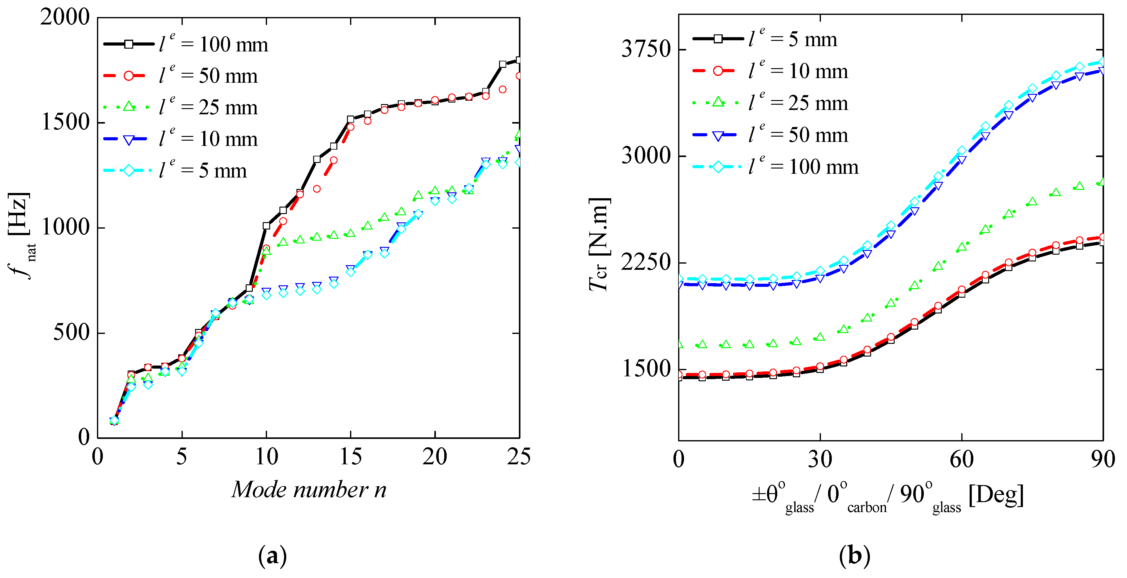
3.4. Meshing Sensitivity Analysis
4. Results
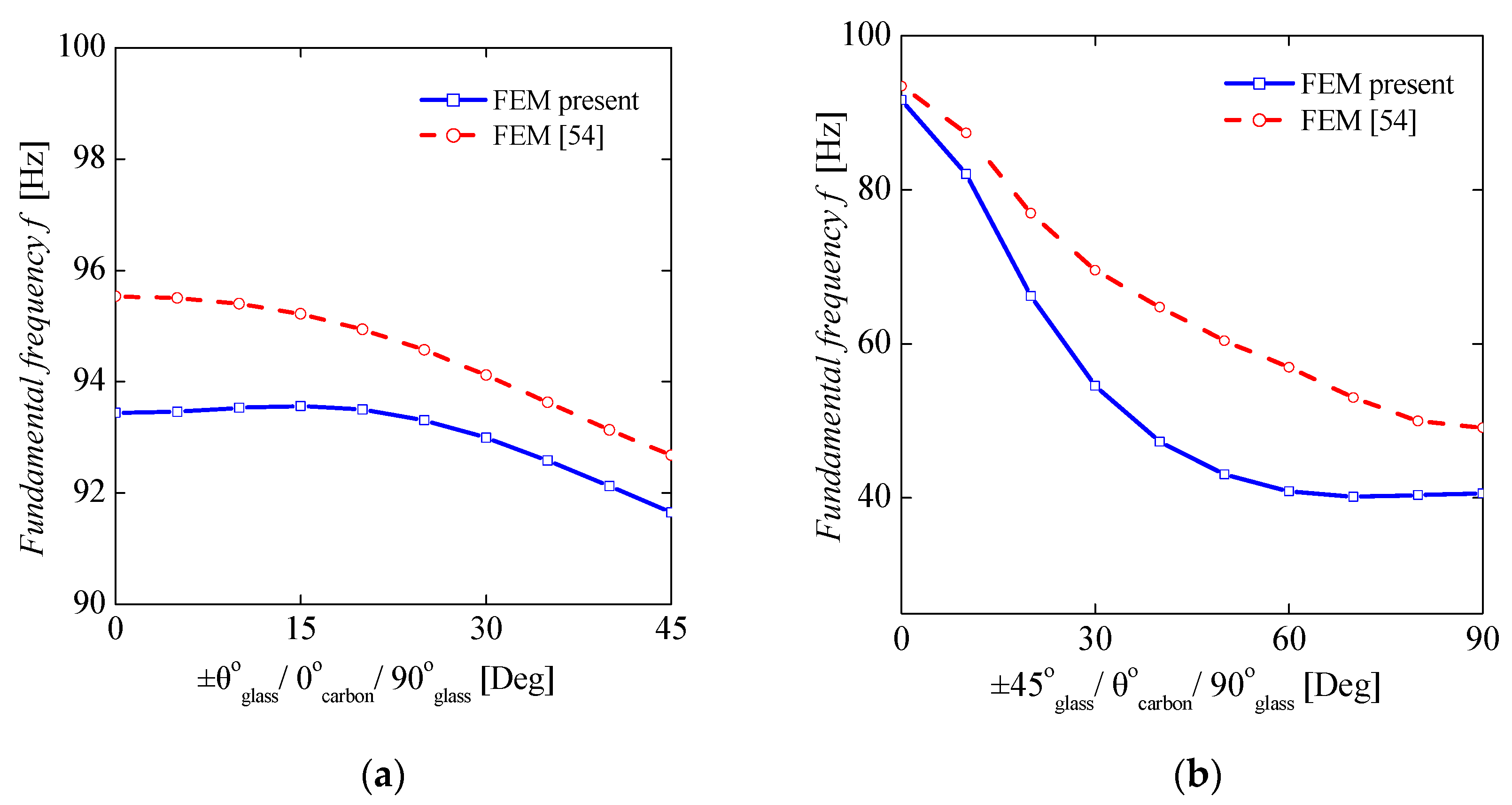
4.1. Validation
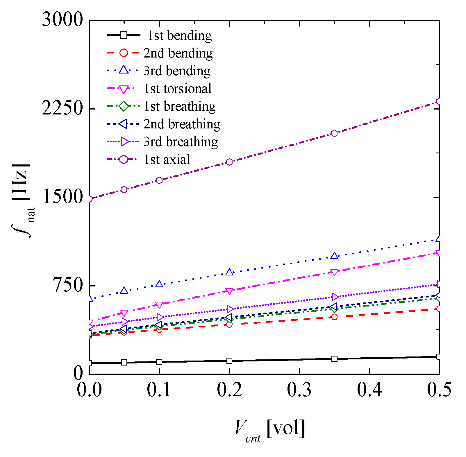
4.2. Effect of CNTs Inclusion on Natural Frequencies and Critical Speed of the Composite Drive Shaft
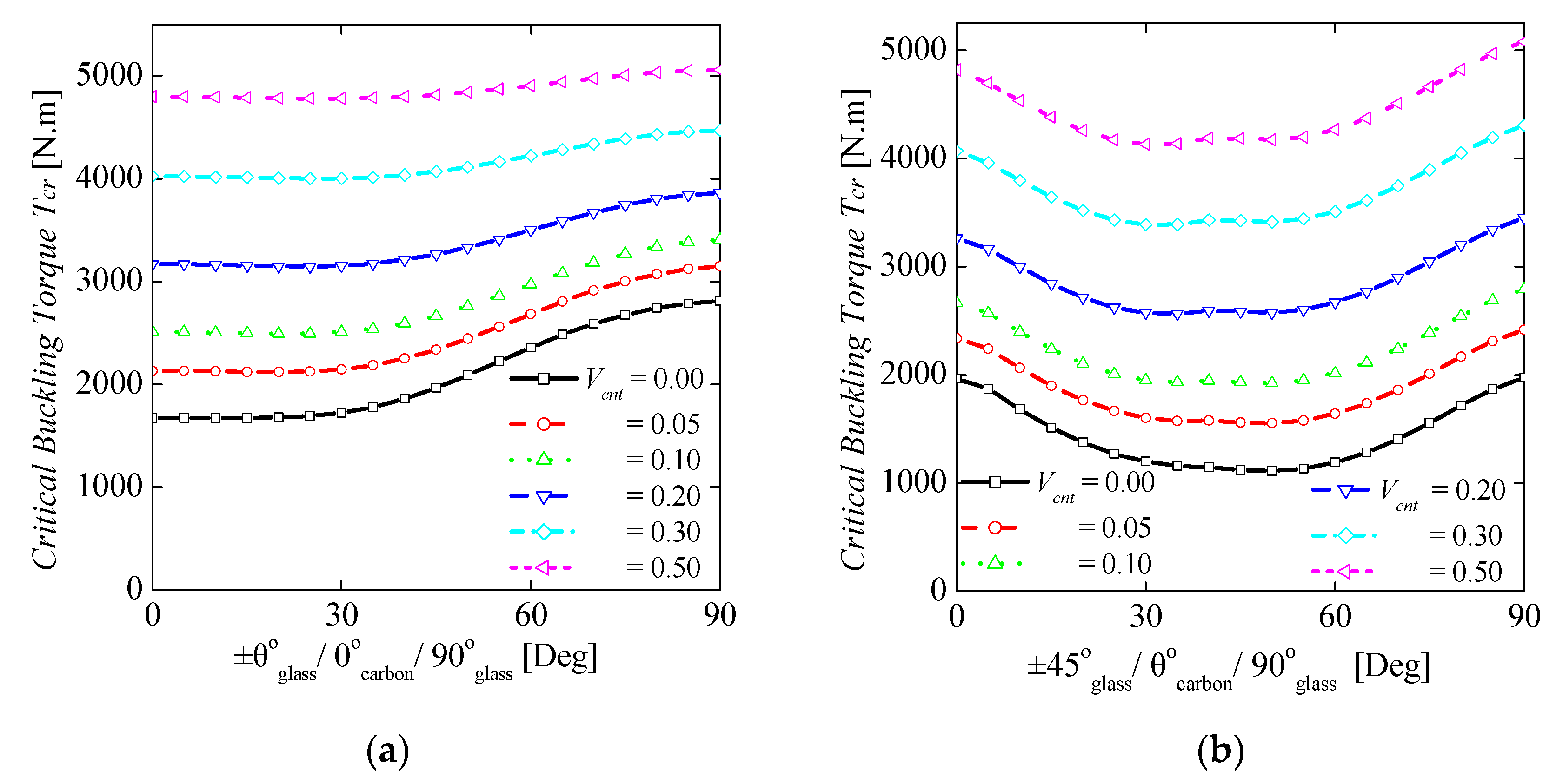
4.3. Effect of CNTs Inclusion on Buckling Torque
5. Conclusions
- The elastic constants E1, E2, G12, and G23 could be increased up to 35%, 582%, 575%, and 607% (e-glass-reinforced polymer lamina) and 9%, 174%, 222%, and 182% (carbon fiber-reinforced polymer lamina), respectively, due to the 0.50 volume fraction of CNTs in the polymer matrix for the specific drive shaft configuration considering uniform dispersion.
- Adding CNTs into the conventional lamina, the natural frequency and critical buckling torque of the laminated composite drive shaft showed significant improvements up to 60% and 145%, respectively.
- The method can be used for design purposes of hybrid fiber-reinforced composite automotive drive shafts with CNTs inclusions.
Author Contributions
Funding
Conflicts of Interest
References
- Godec, M.; Mandrino, D.; Jenko, M. Investigation of the fracture of car’s drive shaft. Eng. Fail. Anal. 2009, 16, 1252–1261. [Google Scholar] [CrossRef]
- Heisler, H. Vehicle and Engine Technology, 2nd ed.; SAE International: London, UK, 1999. [Google Scholar]
- Swanson, S.R. Introduction to Design and Analysis with Advanced Composite Material; Prentice Hall: Hoboken, NJ, USA, 1997. [Google Scholar]
- Seherr-Thoss, H.C.; Schmelz, F.; Aucktor, E. Universal Joints and Driveshafts-Analysis, Design, Applications; Springer: Berlin/Heidelberg, Germany, 2006. [Google Scholar]
- Sun, Z.; Xiao, J.; Yu, X.; Tusiime, R.; Gao, H.; Min, W.; Tao, L.; Qi, L.; Zhang, H.; Yu, M. Vibration characteristics of carbon-fiber reinforced composite drive shafts fabricated using filament winding technology. Compos. Struct. 2020, 241, 111725. [Google Scholar] [CrossRef]
- Cho, D.H.; Gil Lee, D.; Choi, J.H. Manufacture of one-piece automotive drive shafts with aluminum and composite materials. Compos. Struct. 1997, 38, 309–319. [Google Scholar] [CrossRef]
- Elanchezhian, C.; Ramnath, B.V.; Raghavendra, K.S.; Muralidharan, M.; Rekha, G. Design and Comparison of the Strength and Efficiency of Drive Shaft made of Steel and Composite Materials. Mater. Today Proc. 2018, 5, 1000–1007. [Google Scholar] [CrossRef]
- Nehe, S.R.; Ghogare, A.; Vatsa, S.; Tekade, L.; Thakare, S.; Yadav, P.; Shool, P.; Wankhade, P.; Dhakane, V.; Charjan, S. Design, Analysis, Simulation and Validation of Automobile Suspension System Using Drive-Shaft as a Suspension Link. SAE Int. J. Passeng. Cars Mech. Syst. 2018, 11, 129–138. [Google Scholar] [CrossRef]
- Gong, L.; Gao, X.; Yang, H.; Liu, Y.; Yao, X. Design on the driveshaft of 3D 4-Directional carbon fiber braided composites. Compos. Struct. 2018, 203, 466–473. [Google Scholar] [CrossRef]
- Karimi, S.; Salamat, A.; Javadpour, S. Designing and optimizing of composite and hybrid drive shafts based on the bees algorithm. J. Mech. Sci. Technol. 2016, 30, 1755–1761. [Google Scholar] [CrossRef]
- Rastogi, N. Design of Composite Driveshafts for Automotive Applications; SAE Technical Paper Series: Warrendale, PA, USA, 2004. [Google Scholar] [CrossRef]
- Shinde, R.M.; Sawant, S.M. Investigation on glass-epoxy composite drive shaft for light motor vehicle. Int. J. Des. Eng. 2019, 9, 22–35. [Google Scholar] [CrossRef]
- Nadeem, S.S.; Giridhara, G.; Rangavittal, H. A Review on the design and analysis of composite drive shaft. Mater. Today Proc. 2018, 5, 2738–2741. [Google Scholar] [CrossRef]
- Hu, Y.; Yang, M.; Zhang, J.; Song, C.; Hong, T. Effect of stacking sequence on the torsional stiffness of the composite drive shaft. Adv. Compos. Mater. 2016, 26, 537–552. [Google Scholar] [CrossRef]
- Debski, H.; Rozylo, P.; Teter, A. Buckling and limit states of thin-walled composite columns under eccentric load. Thin-Walled Struct. 2020, 149, 106627. [Google Scholar] [CrossRef]
- Liu, P.; Gu, Z.; Peng, X.; Zheng, J. Finite element analysis of the influence of cohesive law parameters on the multiple delamination behaviors of composites under compression. Compos. Struct. 2015, 131, 975–986. [Google Scholar] [CrossRef]
- Galos, J. Thin-ply composite laminates: A review. Compos. Struct. 2020, 236, 111920. [Google Scholar] [CrossRef]
- Bajpai, P.K.; Singh, I. Reinforced Polymer Composites: Processing, Characterization and Post Life Cycle Assessment; John Wiley & Sons: Hoboken, NJ, USA, 2019. [Google Scholar]
- Kumar, S.K.; Krishnamoorti, R. Nanocomposites: Structure, Phase Behavior, and Properties. Annu. Rev. Chem. Biomol. Eng. 2010, 1, 37–58. [Google Scholar] [CrossRef] [PubMed] [Green Version]
- Camargo, P.H.C.; Satyanarayana, K.G.; Wypych, F. Nanocomposites: Synthesis, structure, properties and new application opportunities. Mater. Res. 2009, 12, 1–39. [Google Scholar] [CrossRef] [Green Version]
- Zhao, J.; Wu, L.; Zhan, C.; Shao, Q.; Guo, Z.; Zhang, L. Overview of polymer nanocomposites: Computer simulation understanding of physical properties. Polymer 2017, 133, 272–287. [Google Scholar] [CrossRef]
- Isaac, C.W.; Ezekwem, C. A review of the crashworthiness performance of energy absorbing composite structure within the context of materials, manufacturing and maintenance for sustainability. Compos. Struct. 2021, 257, 113081. [Google Scholar] [CrossRef]
- Mallick, P.K. Fiber-Reinforced Composites: Materials, Manufacturing, and Design; CRC Press: Boca Raton, FL, USA, 2007. [Google Scholar]
- Siochi, E.J.; Harrison, J.S. Structural nanocomposites for aerospace applications. MRS Bull. 2015, 40, 829–835. [Google Scholar] [CrossRef] [Green Version]
- Trimble, S. Lockheed Martin Reveals F-35 to Feature Nanocomposite Structures. Available online: https://www.flightglobal.com/lockheed-martin-reveals-f-35-to-feature-nanocomposite-structures/100174.article (accessed on 26 May 2011).
- Shakil, U.A.; Bin Abu Hassan, S.; Yahya, M.Y.; Mujiyono; Nurhadiyanto, D. A review of properties and fabrication techniques of fiber reinforced polymer nanocomposites subjected to simulated accidental ballistic impact. Thin-Walled Struct. 2021, 158, 107150. [Google Scholar] [CrossRef]
- Tüzemen, M.Ç.; Salamcı, E.; Avcı, A. Enhancing mechanical properties of bolted carbon/epoxy nanocomposites with carbon nanotube, nanoclay, and hybrid loading. Compos. Part B Eng. 2017, 128, 146–154. [Google Scholar] [CrossRef]
- Khoramishad, H.; Alikhani, H.; Dariushi, S. An experimental study on the effect of adding multi-walled carbon nanotubes on high-velocity impact behavior of fiber metal laminates. Compos. Struct. 2018, 201, 561–569. [Google Scholar] [CrossRef]
- Chiou, Y.-C.; Chou, H.-Y.; Shen, M.-Y. Effects of adding graphene nanoplatelets and nanocarbon aerogels to epoxy resins and their carbon fiber composites. Mater. Des. 2019, 178, 107869. [Google Scholar] [CrossRef]
- Novoselov, K.S.; Geim, A.K.; Morozov, S.V.; Jiang, D.; Katsnelson, M.I.; Grigorieva, I.V.; Dubonos, S.V.; Firsov, A.A. Two-dimensional gas of massless Dirac fermions in graphene. Nature 2005, 438, 197–200. [Google Scholar] [CrossRef]
- Iijima, S. Helical microtubules of graphitic carbon. Nat. Cell Biol. 1991, 354, 56–58. [Google Scholar] [CrossRef]
- De Volder, M.F.; Tawfick, S.H.; Baughman, R.H.; Hart, A.J. Carbon nanotubes: Present and future commercial applications. Science 2013, 339, 535–539. [Google Scholar] [CrossRef] [PubMed] [Green Version]
- Kim, G.; Nam, I.; Yang, B.; Yoon, H.; Lee, H.; Park, S. Carbon nanotube (CNT) incorporated cementitious composites for functional construction materials: The state of the art. Compos. Struct. 2019, 227. [Google Scholar] [CrossRef]
- Hu, Z.; Lu, X. Mechanical Properties of Carbon Nanotubes and Graphene-Carbon Nanotubes and Graphene; Elsevier: Amsterdam, The Netherlands, 2014. [Google Scholar]
- Ahmadipour, M.; Arjmand, M.; Le, A.T.; Chiam, S.L.; Ahmad, Z.A.; Pung, S.-Y. Effects of multiwall carbon nanotubes on dielectric and mechanical properties of CaCu3Ti4O12 composite. Ceram. Int. 2020, 46, 20313–20319. [Google Scholar] [CrossRef]
- Georgantzinos, S.; Stamoulis, K.P.; Markolefas, S. Mechanical Response of Hybrid Laminated Polymer Nanocomposite Structures: A Multilevel Numerical Analysis. SAE Int. J. Aerosp. 2020, 13, 1–13. [Google Scholar] [CrossRef]
- Georgantzinos, S.K.; Markolefas, S.I.; Mavrommatis, S.A.; Stamoulis, K. Finite element modelling of carbon fiber carbon nanostructure polymer hybrid composite structures. MATEC Web Conf. 2020, 314, 02004. [Google Scholar] [CrossRef]
- Georgantzinos, S.K.; Giannopoulos, G.I.; Markolefas, S.I. Vibration Analysis of Carbon Fiber-Graphene-Reinforced Hybrid Polymer Composites Using Finite Element Techniques. Materials 2020, 13, 4225. [Google Scholar] [CrossRef]
- Rafiee, M.; Rafiee, J.; Wang, Z.; Song, H.; Yu, Z.-Z.; Koratkar, N. Enhanced Mechanical Properties of Nanocomposites at Low Graphene Content. ACS Nano 2009, 3, 3884–3890. [Google Scholar] [CrossRef]
- Taş, H.; Soykok, I.F. Effects of carbon nanotube inclusion into the carbon fiber reinforced laminated composites on flexural stiffness: A numerical and theoretical study. Compos. Part B Eng. 2019, 159, 44–52. [Google Scholar] [CrossRef]
- Stamoulis, K.; Georgantzinos, S.K.; Giannopoulos, G. Damage characteristics in laminated composite structures subjected to low-velocity impact. Int. J. Struct. Integr. 2019, 11, 670–685. [Google Scholar] [CrossRef]
- Barretta, R.; Brčić, M.; Čanađija, M.; Luciano, R.; de Sciarra, F.M. Application of gradient elasticity to armchair carbon nanotubes: Size effects and constitutive parameters assessment. Eur. J. Mech. A Solids 2017, 65, 1–13. [Google Scholar] [CrossRef]
- Georgantzinos, S.K.; Giannopoulos, G.I. Thermomechanical buckling of single walled carbon nanotubes by a structural mechanics method. Diam. Relat. Mater. 2017, 80, 27–37. [Google Scholar] [CrossRef]
- Hassanzadeh-Aghdam, M.; Ansari, R.; Darvizeh, A. A new micromechanics approach for predicting the elastic response of polymer nanocomposites reinforced with randomly oriented and distributed wavy carbon nanotubes. J. Compos. Mater. 2017, 51, 2899–2912. [Google Scholar] [CrossRef]
- Mehar, K.; Panda, S.K. Elastic bending and stress analysis of carbon nanotube-reinforced composite plate: Experimental, numerical, and simulation. Adv. Polym. Technol. 2017, 37, 1643–1657. [Google Scholar] [CrossRef]
- Georgantzinos, S.K. A new finite element for an efficient mechanical analysis of graphene structures using CAD/CAE techniques. J. Comput. Theor. Nanosci. 2017, 14, 5347–5354. [Google Scholar] [CrossRef]
- Georgantzinos, S.K.; Siampanis, S.G. Size-dependent elastic mechanical properties of γ-graphyne structures: A comprehensive finite element investigation. Mater. Des. 2021, 202, 109524. [Google Scholar] [CrossRef]
- Spanos, K.; Georgantzinos, S.; Anifantis, N. Mechanical properties of graphene nanocomposites: A multiscale finite element prediction. Compos. Struct. 2015, 132, 536–544. [Google Scholar] [CrossRef]
- Lin, F.; Xiang, Y.; Shen, H.S. Temperature dependent mechanical properties of graphene reinforced polymer nanocomposites—A molecular dynamics simulation. Compos. Part B Eng. 2017, 111, 261–269. [Google Scholar] [CrossRef]
- Sun, R.; Li, L.; Zhao, S.; Feng, C.; Kitipornchai, S.; Yang, J. Temperature-dependent mechanical properties of defective graphene reinforced polymer nanocomposite. Mech. Adv. Mater. Struct. 2021, 28, 1010–1019. [Google Scholar] [CrossRef]
- Chandra, A.K.; Kumar, N.R. Polymer Nanocomposites for Automobile Engineering Applications. In Properties and Applications of Polymer Nanocomposites; Springer: Berlin/Heidelberg, Germany, 2017; pp. 139–172. [Google Scholar]
- Kaw, A.K. Mechanics of Composite Materials; CRC Press: Boca Raton, FL, USA, 2006. [Google Scholar]
- Halpin, J.C.; Kardos, J.L. The Halpin-Tsai equations: A Review. Polym. Eng. Sci. 1976, 16, 344–352. [Google Scholar]
- Shokrieh, M.M. Residual Stresses in Composite Materials; Woodhead Publishing Ltd.: Amsterdam, The Netherlands, 2014. [Google Scholar]
- Hyer, M.W.; Scott, W. Stress Analysis of Fiber-Reinforced Composite Materials; DEStech Publications Inc.: Lancaster, PA, USA, 2009. [Google Scholar]
- Talib, A.R.; Aidy, A.; Badie, M.A.; Lah, C.N.A.; Golestaneh, A.F. Developing a hybrid, carbon/glass fiber- reinforced epoxy composite automotive drive shaft. Mater. Des. 2010, 31, 514–521. [Google Scholar] [CrossRef]
- William, T.T.; Dahleh, M.D. Theory of Vibration with Applications; Pearson Education Inc.: London, UK, 1998. [Google Scholar]
- Badie, M.; Mahdi, E.; Hamouda, A.M. An investigation into hybrid carbon/glass fiber reinforced epoxy composite automotive drive shaft. Mater. Des. 2011, 32, 1485–1500. [Google Scholar] [CrossRef]
- Rao, S.S. Vibration of Continuous Systems; John Wiley & Sons: New York, NY, USA, 2007; Volume 464. [Google Scholar]
- Sannikov, A.A.; Vitvinin, A.M. Calculating the critical speed of papermaking machine shafts, considering the stiffness of supports and screens. Chem. Pet. Eng. 1976, 12, 215–217. [Google Scholar] [CrossRef]
- Shokrieh, M.M.; Hasani, A.; Lessard, L.B. Shear buckling of a composite drive shaft under torsion. Compos. Struct. 2004, 64, 63–69. [Google Scholar] [CrossRef]
- Gay, D.; Hoa, S.V.; Tsai, S.W. Composite Materials-Design and Applications; CRC Press: Boca Raton, FL, USA, 2003. [Google Scholar]


| e-Glass Fiber [62] | Carbon Fiber [40] | Epoxy Resin [23] | MWCNTs [39] | ||||
|---|---|---|---|---|---|---|---|
| Ef11 (GPa) | 74 | Ef11 (GPa) | 230 | Em (GPa) | 3.45 | Ecnt (GPa) | 450 |
| Ef22 (GPa) | 74 | Ef22 (GPa) | 15.41 | υm | 0.36 | lcnt (nm) | 20,000 |
| υf12 | 0.25 | υf12 | 0.29 | Gm (GPa) | 1.26 | dcnt (nm) | 20 |
| υf23 | 0.25 | υf23 | 0.46 | tcnt (nm) | 1.5 | ||
| Gf12 (GPa) | 30 | Gf12 (GPa) | 10,04 | dicnt (nm) | 17 | ||
| Gf23 (GPa) | 30 | Gf23 (GPa) | 5.28 | ρcnt (g/cm3) | 0.6244 | ||
| e-Glass Fiber/Epoxy Resin/CNTs Lamina | ||||||
| Vcnt | 0.00 | 0.05 | 0.10 | 0.20 | 0.35 | 0.50 |
| E1 (GPa) | 40.312 | 41.619 | 42.943 | 45.655 | 49.939 | 54.647 |
| E2 (GPa) | 6.874 | 11.871 | 16.570 | 25.204 | 36.651 | 46.890 |
| G12 (GPa) | 2.538 | 4.313 | 5.958 | 9.038 | 13.245 | 17.146 |
| G23 (GPa) | 2.434 | 4.176 | 5.815 | 8.928 | 13.231 | 17.212 |
| υ12 | 0.3027 | 0.3164 | 0.3270 | 0.3355 | 0.3388 | 0.3377 |
| υ23 | 0.4117 | 0.4211 | 0.4246 | 0.4115 | 0.3850 | 0.3621 |
| ρ (g/cm3) | 1.9100 | 1.8457 | 1.7814 | 1.6529 | 1.4600 | 1.2672 |
| Carbon fiber/epoxy resin/CNTs lamina | ||||||
| Vcnt | 0.00 | 0.05 | 0.10 | 0.20 | 0.35 | 0.50 |
| E1 (GPa) | 134.056 | 135.215 | 136.389 | 138.795 | 142.594 | 146.770 |
| E2 (GPa) | 8.079 | 10.579 | 12.335 | 15.080 | 18.639 | 22.200 |
| G12 (GPa) | 3.319 | 4.811 | 5.889 | 7.478 | 9.222 | 10.703 |
| G23 (GPa) | 2.654 | 3.593 | 4.242 | 5.216 | 6.391 | 7.509 |
| υ12 | 0.3198 | 0.3320 | 0.3414 | 0.3489 | 0.3518 | 0.3508 |
| υ23 | 0.4147 | 0.4284 | 0.4387 | 0.4467 | 0.4497 | 0.4486 |
| ρ (g/cm3) | 1.6100 | 1.5607 | 1.5114 | 1.4129 | 1.2650 | 1.1172 |
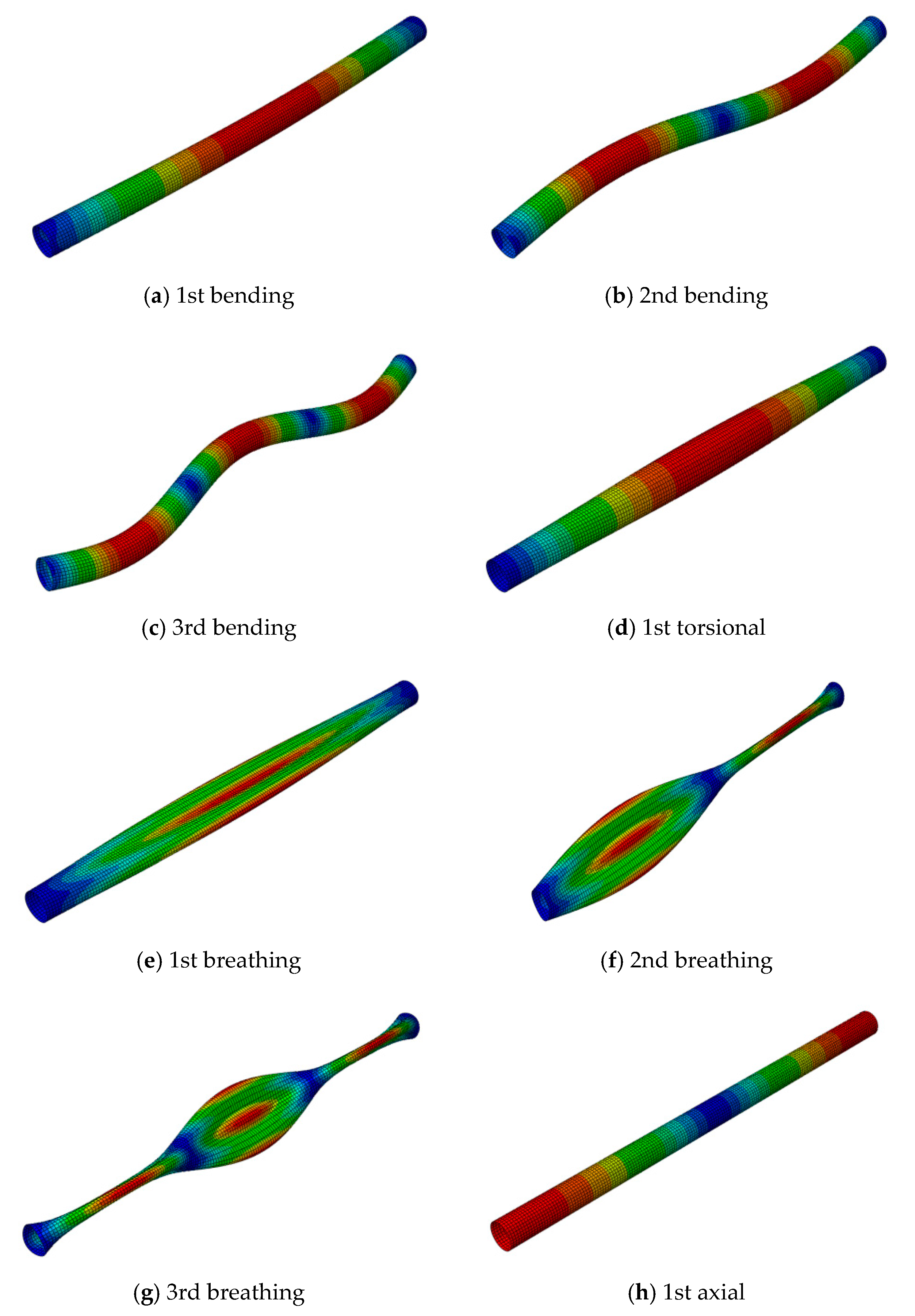
| Mode Shape | FEA (Present) | FEA [58] | Equation (31) | Torsional Buckling Load | FEA Present | FEA [58] | Equation (33) | Analytical [58] |
|---|---|---|---|---|---|---|---|---|
| 1st mode | 91.65 | 90.46 | 96.33 | Critical (Nm) | 1730 | 1830 | 2149 | 2030 |
| 2nd mode | 326.88 | 331.19 | 385.33 | |||||
| 3rd mode | 635.73 | 663.35 | 866.99 |
Publisher’s Note: MDPI stays neutral with regard to jurisdictional claims in published maps and institutional affiliations. |
© 2021 by the authors. Licensee MDPI, Basel, Switzerland. This article is an open access article distributed under the terms and conditions of the Creative Commons Attribution (CC BY) license (https://creativecommons.org/licenses/by/4.0/).
Share and Cite
Georgantzinos, S.K.; Antoniou, P.A.; Markolefas, S.I. A Multi-Scale Method for Designing Hybrid Fiber-Reinforced Composite Drive Shafts with Carbon Nanotube Inclusions. J. Compos. Sci. 2021, 5, 157. https://doi.org/10.3390/jcs5060157
Georgantzinos SK, Antoniou PA, Markolefas SI. A Multi-Scale Method for Designing Hybrid Fiber-Reinforced Composite Drive Shafts with Carbon Nanotube Inclusions. Journal of Composites Science. 2021; 5(6):157. https://doi.org/10.3390/jcs5060157
Chicago/Turabian StyleGeorgantzinos, Stelios K., Panagiotis A. Antoniou, and Stylianos I. Markolefas. 2021. "A Multi-Scale Method for Designing Hybrid Fiber-Reinforced Composite Drive Shafts with Carbon Nanotube Inclusions" Journal of Composites Science 5, no. 6: 157. https://doi.org/10.3390/jcs5060157