Abstract
The fulfilment of the crash is a demanding requirement for a Tiltrotor. Indeed, such a kind of aircraft, being a hybrid between an airplane and a helicopter, inherits the requirements mainly from helicopters (EASA CS 29) due to its hovering ability. In particular, the fuel storage system must be designed in such a manner that it is crash resistant, under prescribed airworthiness requirements, in order to avoid the fuel leakage during such an event, preventing fire and, thus, increasing the survival chances of the crew and the passengers. The present work deals with the evaluation of crashworthiness of the fuel storage system of a Tiltrotor (bladder tank), and, in particular, it aims at describing the adopted numerical approach and some specific results. Crash resistance requirements are considered from the earliest design stages, and for this reason they are mainly addressed from a numerical point of view and by simulations that treat both single components and small/medium size assemblies. The developed numerical models include all the main parts needed for simulating the structural behavior of the investigated wing section: the tank, the structural components of the wing, the fuel sub-systems (fuel lines, probes, etc.) and the fuel itself. During the crash event there are several parts inside the tanks that can come into contact with the tank structure; therefore, it is necessary to evaluate which of these parts can be a damage source for the tank itself and could generate fuel loss. The SPH approach has been adopted to discretise fuel and to estimate the interaction forces with respect to the tank structure. Experimental data were used to calibrate the fuel tank and foam material models and to define the acceleration time-history to be applied. Thanks to the optimized foam’s configuration, the amount of dissipated impact energy is remarkable, and the evaluation of tanks/fuel system stress distribution allows estimating any undesired failure due to a survivable crash event.
1. Introduction
Tiltrotors are aircrafts that lie between rotorcrafts and fixed wing aircrafts. In the framework of the European Clean Sky 2 research program (CS2), among the Integrated Technology Demonstrators, the development up to TRL6 (experimental flight) of a Tiltrotor Technology Demonstrator named NGCTR-TD (Next Generation Civil Tiltrotor Demonstrator) [1], led by aircraft manufacturer Leonardo, Helicopters Division, is scheduled. This peculiar vehicle can represent a brick within European door-to-door mobility that is able to overcome infrastructural constraints due to the congestion of airports envisaged for the future in which air traffic is forecasted to increase globally with mean Compound Annual Growth Rates (CAGR) of about 3.5% in the next 30 years [2]. In fact, the tiltrotor is able to take off and land vertically without airports, and in cruise it has superior performances (cruise speed) with respect to rotorcrafts. This means of transport can be used not only for civil air transport (we can imagine a one hour travel directly from the downtown Manhattan heliport to Washington, D.C.) but also for specialized societal needs, such as medical evacuation, search and rescue and other utility roles where airport infrastructure is limited or unavailable, while also adhering with ambitious environmental goals [3]. Due to their peculiar nature, tiltrotors inherit requirements coming both from fixed wing aircrafts certification specifications (e.g., EASA CS 25) and from helicopters (e.g., EASA CS 29). One of these requirements covers the crashworthiness aspect, which comes from the common ability of hovering with respect to helicopters and tiltrotors. This aspect has a tremendous impact both on wing design and on the fuel storage system concept. In fact, for the tiltrotor under consideration, the wing has to be able to respect strength, buckling and stiffness requirements [4,5]; under a survivable crash, to break in a defined section in order to alleviate the inertial load on the fuselage; and to allow crew and passenger to safely escape outside the vehicle. On the other hand, the fuel storage system has to be based on the bladder concept and not on the wet-wing concept (which is common practice for fixed wing aircrafts) [6]. The fuel system has a stringent crashworthiness qualification requirement coming from helicopters, namely CS 29.952, which requires that the system can be dropped from 50 feet with no fuel leakage after the crash in its most critical configuration.
The present work is developed within the research framework of CS2 dedicated to the development of NGCTR-TD; in particular, the activities lie within the perimeter of the project DEFENDER aimed at developing up TRL6, the fuel storage system of the NGCTR-TD. The crashworthiness aspect has been considered from the very preliminary stages of the fuel tank design. In addition, among the different outputs of the project, there is the setup of methodologies and of experimentally validated models able to predict the crash behavior of the most critical tank and its surrounding structure.
The majority of the available literature on the fuel tanks crashworthiness is mainly concerned with helicopters fuel tanks. In 2002, FAA issued a report [7] in which the historical efforts that led to the state of the art were presented, at that time, in military helicopter fuel systems, and the modifications to civil certification standards in Title 14 Code of Federal Regulations (CFR) Part 27 (Normal Category Rotorcraft) and Part 29 (Transport Category Rotorcraft) were also presented. The focus was on steering the effort on avoiding post-crash fire, since it still represents a factor that makes the difference in a survivable crash for what concerns fatalities and injuries. In the report, a summary of the most promising tank material and architecture solutions was recalled, such as high strength and energy absorbing properties of flexible bladders and the use of flexible fuel lines and breakaway self-sealing couplings at the firewall to prevent fuel line failure. The first extensive testing campaign of crash-resistant fuel tanks occurred in 1963, when several MIL-T-27422A qualified fuel cells were drop tested in two CH-21 helicopters, with a severe crash in which the bladders’ material was punctured by the jagged metal. That experience showed that the standards that governed the design at that time were not adequate; this resulted in the addition, in the subsequent revisions of MIL-T-27422, of chapters dealing with the resistance of material to puncture and tear propagation, which is equally as important as the material’s tensile strength. In 2004, NASA issued a report [8] in which several test campaigns performed at NASA LRC were presented; the following tests are including among them: a qualification test on of an external fuel system for the UH-1 Huey Helicopter, with the entire helicopter under crash test, which was successful, i.e., no leakage; qualification tests of an external fuel tank for the UH-60 Black Hawk Helicopter, which was considered successful since both external fuel tanks survived the severe impact condition with only minor leakage, even though they experienced a large transient pulse during the impact test. These findings validated the crash resistance of the modified fuel tank design. In [9], the crashworthiness characteristics of a helicopter fuel tank were studied by means of experimental testing and numerical simulations. The focus of the work was aimed at better understanding the structural causes behind the problem of fire ignition, and it was conducted in two phases: the first one was performed on simple structures representative of real fuel tanks (material and sizes comparable with those used in helicopters components) and the second phase used a real fuel tank extracted from a real helicopter. From a numerical point of view, the main problems that were faced by the author were as follows: the movement of the fluid inside the tank (partial filling of the entire volume); the simulation of the flow of the fluid outside the tank in the case of external structure failure; and rivet modeling. The approach used was an Arbitrary Lagrangian Eulerian (ALE) coupling making use of two Lagrangian structures: one representing the real external structure of the tank and the other possessing material stiffness of orders of magnitude less than the first one, representing the fluid. The numerical simulations, performed with MSC DYTRAN 4.0, were in agreement with the experimental data and allowed setting up the models to be used for the second phase, i.e., a full scale experimental numerical correlation. Based on these available tests campaign, the ALE approach was compared to the Lagrangian FE in a work focused on the water impact of a filled tank [10]. The two approaches were used both to simulate the fluid inside the tank and the water impacted. The experimental data pertaining to ground impact were used to compare the two approaches and set up the model to be used for the water impact. The results obtained showed a better suitability of the Lagrangian FE approach in the very initial stages of the impact, whereas the ALE approach resulted in a qualitatively accurate description of the sloshing of fluid, with further margins of improvements by increasing the number of the elements. For the water impact, the two mentioned approaches were studied to simulate the water impacted by the tank, highlighting that the simulation performed using the ALE approach for the fluids provided less severe decelerations with respect to the Lagrangian FE approach. ABAQUS/Explicit was used in [11] to numerically study the impact with the ground of a filled tank of a medium weight helicopter and correlate the results with an experimental drop test. Metallic parts of the model used isotropic elastic-plastic constitutive laws, while orthotropic constitutive laws were used to model honeycomb parts. Strain rate effects were taken into account. Riveted joints were modelled using the contact pair algorithm, and their failure law was based on experimental data. Bladder was modelled with an elastic constitutive law based on tests, whereas the mechanical behavior of the water inside the tank (80% filling) was modelled with user subroutines “VUMAT”. A general contact algorithm was used for the interaction between water, bladder, tank structure and ground. The experimental–numerical correlation showed that the FE model was able to reproduce the drop test; consequently, numerical analysis was a reliable prediction tool. In [12], two FE models of a helicopter fuel tank are compared: one is for an uncovered tank, i.e., without protection frame, and the other is for fuel tank with protection frame. The methodology used is based on the coupled Lagrangian FEM and Eulerian formulation based Finite Volume Method (FVM). The bladder material model was based on tensile tests in longitudinal and lateral directions, whereas the Belytschko–Tsai shell theory was employed to model the textile elements. The comparison between the two models’ results show that the protective frame is able to significantly reduce tank deformation, thus resulting in a necessary item to improve the tank’s crashworthiness. Kim and Kim [13] numerically simulated the crash behaviour of a fuel cell group of a helicopter, based on the Smoothed Particle Hydrodynamics (SPH) method for fluid structure interaction (FSI) by using the commercial software LS-DYNA. Using the SPH seems to be the most feasible approach for evaluating fluid–structure interaction; furthermore, it was able to reproduces the sloshing of the fluid inside the tank accordingly with the intuition and the common experience [10,14]. SPH allows limiting computing time and resources with respect to ALE in an easier manner, and it is more stable and robust. The researchers used the simulation in order to provide crashworthy design indications to the fuel tank system before dropping the real test article and lowering the risk of failure of the test itself, which is expensive and requires long term preparation; if it failed, it would have significant impacts on the critical path to the flight of the aircraft.
Yang et al. [15] investigated the dynamic response of the nylon woven fabric composite fuel tank striking on the ground based on the multi-material ALE method and compared the results of simulations with the experimental drop test of a cubic fuel tank (test in accordance with MIL-DTL-27422). Tank material data came from experimental coupon tensile tests. The Gruneisen equation was chosen as the equation of state of the water inside the tank. The comparison between the numerical and experimental time histories of the impact force exerted on the fuel tank showed a good correlation both for what concerns the shape of the curves and the peak forces in which the values were similar.
In the present work, the numerical activity developed in the first stages of the design of the fuel storage system of the NGCTR-TD is presented. In particular, the most critical fuel tank bay has been considered in the study. The numerical simulations are carried out with the commercial code LS-DYNA and use the SPH approach for fluid modelling inside the tank. The mechanical properties of the material system adopted for the tank are based on experimental tests at the coupon level. The work presented in this paper is framed inside a broader roadmap foreseen in the project and aimed at setting up experimentally validated full scale models for the fuel tanks’ crashworthiness. The roadmap is depicted in Figure 1.
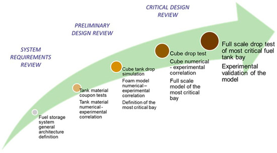
Figure 1.
Building block roadmap for experimentally validated high fidelity models for tanks’ crashworthiness in the DEFENDER project.
It foresees a building block approach that starts from tank material characterization at the coupon level, and it develops incremental models from material coupon models to standalone tanks of cubic shape according to MIL-DTL-27422, validated by means of experimental cube drop tests, up to full scale tests including the tanks and the surrounding wing structure. The incremental approach is a reasonable method for the ultimate goal of certification by analysis [16,17], which is a desired objective of the aircraft manufacturers once the approach is experimentally validated [18,19], in order to reduce the cost and time associated with experimental full scale crash tests [20,21]. In the past, fuel tank crashworthiness mainly relied on experimental testing, which was expensive and difficult to perform. Nowadays, explicit codes have resulted to be successful in analysing crash events; once their reliability is demonstrated by numerical–experimental correlation, the number of tests that need to be performed in order to achieve airworthiness certification can be reduced, for example, in the case of design modifications that can be certified without repeating experimental tests. The specific application to tiltrotors makes this study a reference with respect to fuel storage system development approaches and crashworthiness behaviour knowledge for many reasons:
- -
- Tiltrotors fuel tanks are generally placed in the wing box with a limited available space with a completely different crashworthiness behaviour with respect to fuel tanks installed in the helicopter fuselage;
- -
- Complex tanks’ geometry in terms of adapting them to wing torque box;
- -
- Presence of peculiar systems able to break-away part of the wing during crash event without damaging the tanks installed inside.
In addition, to the authors’ best knowledge, no published studies about the crashworthiness of a fuel tank with respect to unique worldwide existing civil and military tiltrotors have been previously published.
2. Materials and Methods
This work is framed within the roadmap as one of the first steps to validate a full scale new numerical methodology in order to predict mechanical behavior during a crash event in terms of the most critical wing section (including the fuel system) of the NGCTR-TD. In this first step, the simulations pertain mainly to the fuel storage system, with the aim of reaching a design compliant with crashworthiness requirements. In particular, according to the above-mentioned requirements, the fuel storage system must be designed to avoid failures that may produce fuel leakage even during crash events. Therefore, the research object of the present paper has been conducted in order to achieve a numerical methodology capable of guiding the design phase of the fuel storage system.
The drop test conditions refer to the airworthiness standards for the transport category rotorcraft, particularly to the extract CS 29.952 [22], which concerns the fuel system’s crash resistance. In detail, the certification specification asks for a drop test conducted according to the following requirements:
- -
- The drop height must be at least 50 feet;
- -
- The drop impact surface must be non-deforming;
- -
- The tanks must be filled with water up to 80 percent of the normal, full capacity;
- -
- The tank must be enclosed in a surrounding structure representative of the installation;
- -
- The tank must drop freely and impact in a horizontal position ± 10°;
- -
- After the drop test, there must be no leakage.
According to the leading Leonardo Helicopters, the critical wing section has been chosen as the one just outboard of the wing to fuselage fittings, and it contains two tanks called 2A and 2B (Figure 2).
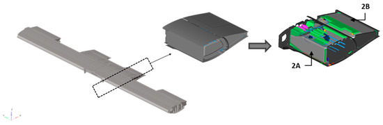
Figure 2.
Critical wing section of the Next Generation Civil Tilt Rotor.
An experimental drop test has been carried out according to the above requirements by Leonardo Helicopters for a similar application. The acceleration time history acquired during the experimental test, performed according to CS 29.952, is shown in Figure 3 (normalized values).
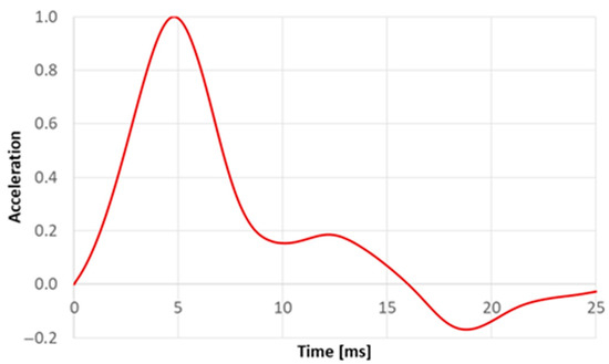
Figure 3.
Input acceleration time history.
By possessing the former test article, a comparable structure and a total dropped mass and simultaneously aiming at simulating the same drop test from 50 ft height, the experimental acceleration has been exploited as an input loading condition of the numerical simulation presented in this work.
In the preliminary phase of the design focused on the development of the optimal design of the fuel storage system, the wing structure has been modelled as rigid, and the acceleration pulse shown in Figure 3 has been applied to it. This approach was deemed the most conservative for the fuel storage system in terms of energy absorbed.
The drop has been simulated by an explicit analysis performed with the software Ls-Dyna already validated for the simulation of aeronautical structure in drop test conditions [23].
During the crash event, there are several parts of the fuel system that can come into contact with each other and with the tank structure; therefore, it is mandatory to evaluate which of these can be a damage source for the tank itself and, thus, may generate fuel leakage. Another important aspect is fluid–structure interaction. In fact, under the action of severe acceleration fields, the fluid could stretch the tank structure and cause failures or come into contact with other fuel system parts, compromising the tank’s integrity. Therefore, the developed numerical model considers all the main parts needed for a consistent structural behaviour of the investigated bladders under dynamic load conditions: the tank, the structural components of the wing made in high performance composite materials, the fuel sub-systems (fuel lines, probes, etc.) and the foam blocks. In accordance with the crashworthiness requirements, the tanks are 80% filled with water [22]. Figure 4 and Figure 5 show the surrounding structure and fuel systems components taken into account in the reported investigation. The entire numerical model has been discretized by considering an average mesh size equal to 5 mm. Such a value has been defined by means of a convergence mesh study that, for the sake of brevity, is not reported in this context. Table 1 provides further information about the FE model and material system adopted by each sub-component.

Figure 4.
Surrounding structure of the fuel storage system.
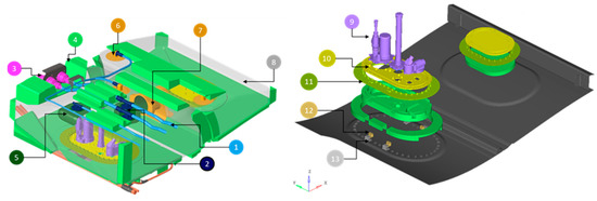
Figure 5.
Fuel storage system, fuel gauging and fuel distribution system within the wing box.

Table 1.
Summarized description of the fuel storage/distribution system components modelling.
Due to the complexity of the full-scale model, preliminary studies on some components have been carried out in order to achieve calibrated and validated sub-models. Indeed, a numerical–experimental correlations campaign of the tensile test performed on the specimen of the tank structure and rubber structure has been performed in order to suitably simulate the high deformations that such materials can reach up to failure. In a similar manner, the numerical–experimental correlations of both static and dynamic compression tests on the foam specimens have been carried out with the aim to establish the level of absorbed energy. Similarly, an in-depth study has also been carried out on some fuel system equipment placed inside the 2A tank. In detail, a compression test on a component of this equipment has been performed in order to ensure that it does not put at risk the tank structure during the drop when it comes into contact with this component.
In order to simulate the contact between every component of the model, a single surface algorithm has been introduced with the card “*CONTACT_AUTOMATIC_SINGLE_SURFACE.” For this contact, the option “soft constraint formulation” (SOFT = 1) has been adopted and is recommended for the interaction between components with significantly dissimilar mechanical properties. Furthermore, the card “*CONTACT_TIED_NODES_TO_SURFACE” has been implemented in order to realize the connection between the distribution lines and the tanks.
2.1. Material of the Tank
The tanks are made of SP102, an innovative layered structure capable of ensuring impact resistance while maintaining flexibility and also low weight. It is composed of an external high tenacity fabric layer and an inner rubber layer. An internal film, applied in liquid status, is embedded within the wall construction to prevent fuel barrier diffusivity (Figure 6).
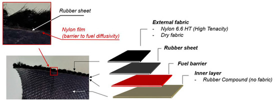
Figure 6.
Innovative fuel tank structure: SP102.
A numerical–experimental correlation, based on tensile tests of tank materials performed at coupon level, has been performed. The outer layer of dry fabric is made up of nylon yarns interwoven in a crosshatch pattern. Due to the orthotropic behaviour of this type of material, the entire structure is orthotropic (the other layers are isotropic); therefore, two tensile tests in weft and warp directions, respectively, have been carried out [12].
The specimens are 50 mm width, 500 mm long and 2 mm thick. The experimental test (Figure 7) has been performed considering a displacement rate equal to 300 mm/min, and the gauge length is 100 mm.
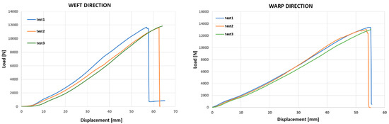
Figure 7.
Tensile test results for weft and warp direction.
Historically, LS-DYNA has provided a number of options for modelling of fabric, all connected with the keyword “MAT_FABRIC.” [24] This material is a variation on the Layered Orthotropic Composite material model and is valid for only 3 and 4 node membrane elements [23] and assumes that the fabric can be modelled as a membrane without bending resistance. From a pure constitutive viewpoint, Formulation 14 provides non-linear uncoupled fiber behaviour. In addition to being a constitutive model, this model also invokes a special membrane element formulation that is better suited to the large deformations experienced by fabrics. The use of this material card allows simulating two different hyperelastic behaviours in the weft and warp directions by the introduction of two Young modules. The characteristic non-linear behaviour is provided by the element formulation 14, which allows setting two different load/unload curves along the two orthotropic directions (warp and weft) [25]. The LOAD/UNLOAD curves in warp and weft directions can be inputted by using engineering stress versus strain (Figure 7) that is easily derived from the experimental results illustrated in Figure 8.
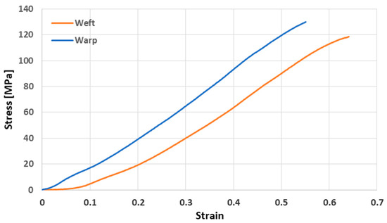
Figure 8.
Stress vs. strain curves in the two orthotropic directions.
Figure 8 shows load vs. displacement curves under tensile loading conditions, both for weft and warn directions. The average maximum load for weft direction is about 115 kN, while the average maximum load for warn direction is about 132 kN.
The Finite Element Models of the coupon and the boundary conditions are shown in Figure 9. The tensile load is applied to the free edge of the coupon through a prescribed displacement equal to the ultimate displacement detected in the experimental tests. Two different numerical tests have been performed on the same numerical model (Figure 9), changing only the orientation of the shell elements and the applied boundary conditions. In order to correlate the tensile test along weft/warp directions, the shell elements have been oriented with the weft/warp direction parallel to the load. Furthermore, two different boundary conditions have been applied: prescribed displacement with a velocity of 300 mm/min of 55 mm for warp direction and 64 mm for the weft one.
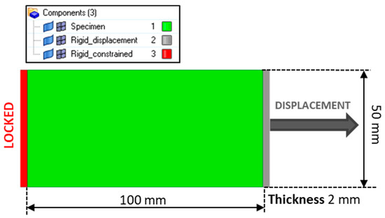
Figure 9.
Numerical tensile test of SP102 coupon.
Figure 10 and Figure 11 show the comparison between experimental tests and the numerical simulations in terms of force-displacement charts.
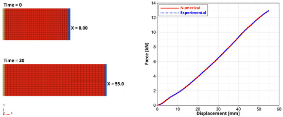
Figure 10.
Numerical–Experimental tensile test comparison. Warp direction.
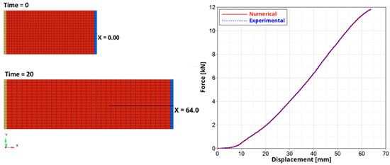
Figure 11.
Numerical–Experimental tensile test comparison. Weft direction.
The results underline a good correlation between the predicted curves and the experimental data in both weft and warp direction. This means that the hyperelastic material model and the performed material model calibration were able to provide consistent results. Therefore, this material model, validated with the tensile test correlation, has been used in the full-scale model in order to simulate the structure of tanks 2A and 2B.
As already highlighted, the application of an orthotropic material model results in the necessity of setting the correct orientation of the shell elements. In the full-scale model, the shell elements, which make up tanks 2A and 2B, have been oriented according to packaging sequence with the warp direction inclined at forty-five degrees with respect to the x-axis (Figure 12).
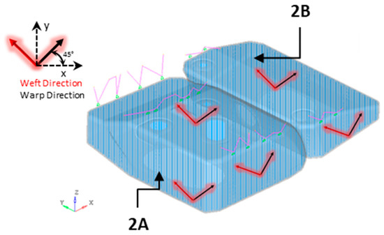
Figure 12.
Material reference system on tank according to manufacturing process.
The specific formulation for large deformations used in material model 34 results in the evaluation of stress and strain as second Piola–Kirchhoff stress and Green’s strain. Green’s strain is defined as follows:
where is the ratio between the final length l and the initial length of the line element.
In order to evaluate the failure strain along weft and warp directions, the relationship between engineering and Green’s strain has been used.
Here, is the engineering strain. The ultimate engineering strain along the two orthotropic directions can be derived from the experimental tensile test results; subsequently, the corresponding Green’s strain can be evaluated by using Equation (2). The limit values are reported in the Table 2.
Table 2.
Tanks structure material limits.
The Green’s failure strain in Table 2 has been adopted as threshold values for the tanks’ strain evaluation in the full-scale drop analysis.
2.2. Water Model and Fluid-Structure Interaction
During the drop, the tank is 80 percent filled with water, as prescribed by the crashworthiness requirements. The impulsive nature of the event results in the need of simulating the water sloshing inside the tanks. Indeed, the motion of the fluid inside the tank influences the deformation of the tank itself and, consequently, the configurations assumed during the crash event. For this reason, a detailed model of the fluid inside the tanks has been realized with the aim of predicting the conversion of fluid kinetic energy in the internal energy of the tanks’ structure (i.e., elastic, plastic, or rupture energy). The greatest difficulty in modelling a fluid in a multiphase structural simulation is related to the large displacements typical of the fluid phase during the analysis. In order to overcome the high deformation limits of the Finite Elements Method, the water has been modelled through the meshless SPH method. The first step of the application of the SPH method is the discretization of the domain by a distribution of particles. Subsequently, the influence distance between the particles, known as the “smoothing length”, is defined. The influence domain of each particle is a volume of radius proportional to the smoothing length “h”, over which field variables and properties are approximated by a kernel function (Figure 13). The position of each particle is affected by the surrounding particles within the influence domain [26].
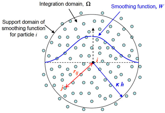
Figure 13.
Schematization of the smoothing function within the integration domain of a particle [27].
LS-DYNA computes the initial smoothing length, h0, for each SPH part by taking the maximum of the minimum distance between every particle. Every particle has its own smoothing length, which varies in time according to the following equation:
where ∇ν is the divergence of the flow [28]. Equation (3) highlights that the smoothing length increases as particles separate and reduces as the concentration increases. This scheme is designed to hold constant the number of particles in each neighbourhood. In addition to being governed by the above evolution equation, the smoothing length is constrained to be between a user-defined upper and lower value.
The conservation of mass per unit volume equation establishes that the divergence of the flow is zero for an incompressible flow:
where ρ is the fluid density. Therefore, in order to satisfy Equation (5), Equation (3) results in a constant smoothing length.
From a numerical viewpoint, this behavior can be achieved by setting a unit value for the parameters HMIN and HMAX (Equation (4)). Thus, in the SPH section, these parameters have been set equal to 1 in order to simulate the incompressible behavior typical of water flow.
The fluid-dynamic behaviour of the water is governed by the Gruneisen Equation of State (EoS), which relates pressure to the change of the volume of the particles. This EoS defines pressure for compressed materials as follows.
For expanded materials, it is defined as follows:
where E is the internal energy per initial volume, C is the sound velocity of the material, , and are the coefficients of the slope of particle velocity, is the Gruneisen gamma and a is the first order volume correction to . The constants C, , , , and a are user defined input parameters. Compression is defined in terms of the relative volume, V, as follows.
In the calculation, the parameters are assumed to have the following values: C = 1650 m/s, µ = 8.684 × 10⁻⁴, S1 = 1.192, S2 = 0.92, S3 = 0, γ0 = 0.35 and a = 0 [15,29].
In order to complete water modelling, a material type 9 (MAT_NULL) has been associated with the water particles. This material must be used with an EoS in order to describe pure viscous behaviour through a deviatoric constitutive equation:
where is the generic deviatoric stress, the dynamic viscosity and the generic deviatoric strain rate.
The choice of the SPH approach to model the water has been influenced by this numerical interaction. In fact, when the fluid is modelled by SPH elements and the container structure is modelled by FEA elements, the fluid–structure interaction can be easily handled by the node relative to surface contact. This type of contact is a master–slave penalty algorithm in which the continuum bodies are the master bodies and the SPH particles are the slaves. The interaction between the water modelled by means of the above methodology and the bladder fabric structure has been validated in previous work and focused on the drop test of a cubic soft bladder filled with water [29] (refer to roadmap in Figure 1). The number of SPH elements inside the full-scale model is 1409634.
2.3. Foam Material Model
In order to mitigate the damage risk of the tanks structure and the other components inside the wing, foam blocks have been introduced in the empty regions between tanks and wing structure to support the tanks during the operative load conditions and to further absorb a relevant amount of energy during crash events.
Different types of foam have been selected for this application depending on the following: compression properties, weight, manufacturability and fuel suitability. For this purpose, a numerical investigation has been carried out in order to minimize weight while ensuring enough mechanical crash resistance. The first step has been the calibration of the foam model with reference to the experimental compression tests performed by foam suppliers. Subsequently, an optimization procedure has been applied with the aim of reaching the best foam blocks configuration according to the requirements.
The following types of foams have been selected for the critical wing bay:
- Closed cell crosslinked polyethylene foams;
- Expanded polypropylene.
Experimental dynamic impact tests have been performed on several foams (different densities). The impact velocity is equal to 2.2 m/s at 23 °C. The experimental test has been performed with the drop tester IM100 and Imatek impact analysis software. The test method involved the drop of a mass on a cubic test piece 50 × 50 × 50 mm at a pre-determined velocity of 2.2 m/s. The impact weight for each test has been selected in order to reach the maximum compression of 85% [30]. Table 3 reports the load conditions and the sample dimensions of the dynamic compression test performed on the expanded polypropylene of density equal to 80 g/L.
Table 3.
Impact test condition for expanded polypropylene of density 80 g/L.
The experimental test results are expressed in terms of stress-strain curves in Figure 14.
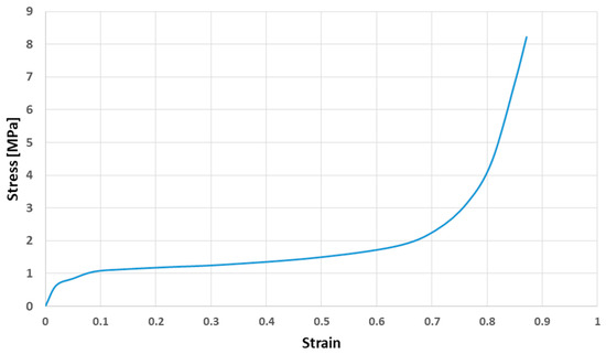
Figure 14.
Experimental stress-strain curves for 80 g/L expanded polypropylene.
The numerical model is shown in Figure 15. The foam specimen has been modelled by using tetrahedral elements with one point constant stress with nodal pressure averaging formulation. The material chosen for this application is a low-density foam material model in which the inputs include density, elastic-modulus and a load curve to define its engineering stress-strain behaviour for compression, reported in the Table 4. The adopted material model does not include the progressive damage option. The main scope of the work is to study the global response of the tank in order to highlight possible damage sources on the tank. The consideration of the foams’ ability to recover their original shape is quite conservative, since the foams are still able to transfer a considerable amount of energy to the tank after the maximum crushing; thus, activating further sloshing/shaking of the internal metallic components could hit and damage the tank.
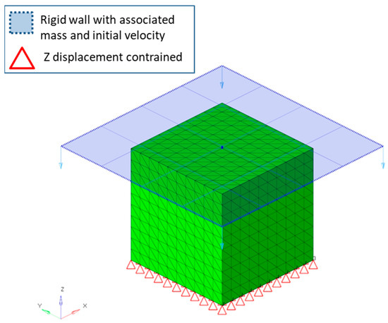
Figure 15.
Numerical model of the foam compressive test.
Table 4.
Parameter setting for the low-density foam material card.
The impact weight has been associated with a rigid wall moving downward with the velocity of 2.2 m/s. The opposite face of the sample is constrained in z displacement, as illustrated in the Figure 15.
From Figure 16 it can be inferred that the dynamic compression property is accurately simulated since the two curves overlapped each other.
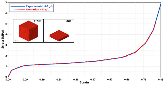
Figure 16.
Comparison of numerical and experimental stress-strain curves for 80 g/L expanded polypropylene.
A campaign of numerical–experimental correlations has been carried out in order to compare the compression performance of different density foams specimens. As an example, a comparison between the expanded polypropylene of densities 150 g/L, 120 g/L and 80 g/L is reported. It shows the process that has resulted in the optimized configuration of the foam blocks. The impact weight for each test (Table 5 has been selected to ensure a minimum strain of 85% on the samples [30].
Table 5.
Impact weight for the dynamic compression tests of the 80 g/L, 120 g/L and 150 g/L expanded polypropylene.
Figure 17 shows the comparison between experimental and numerical stress-strain curves for each density analyzed. The numerical curves correlate accurately with the experimental ones for each density. Furthermore, Figure 17 highlights that foam stiffness increases with density.
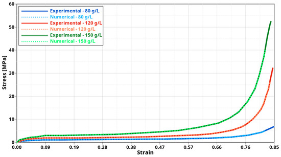
Figure 17.
Comparison of numerical–experimental stress versus strain curves for 80 g/L, 120 g/L, 150 g/L expanded polypropylene.
In order to select the optimal configuration for the critical foam block, a further comparison between these three types of foams has been carried out by imposing an equal impact weight in the numerical dynamic compression tests. The numerical model is identical to the one illustrated in the Figure 15, with the exception that the weight associated with the rigid wall has been inputted to be equal to 70 kg for each analysis. In the following figures, the compression behaviour comparison is reported, with a focus on the dynamic compression curves of each tested foam (Figure 18) and on the maximum compression reached. The results underline that the maximum compressions reached by the 150 g/L and 120 g/L samples are, respectively, about 52% and 70% of the value accomplished by the 80 g/L one.
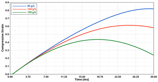
Figure 18.
Compression versus time curves of the 80 g/L, 120 g/L and 150 g/L in the impact test with equal compression load.
The above study has been used to test the concurrent solutions for the foam blocks configuration. In fact, the validated material model has been applied to the foam blocks inside the full-scale model by positioning the most resistant foams in the areas mostly loaded during the drop test. Subsequently, a series of full-scale analysis have been performed in order to select the best configuration in terms of weight to strength ratio with the aim of reaching the lighter configuration. Figure 19 shows the transition from the preliminary configuration to the optimized one.
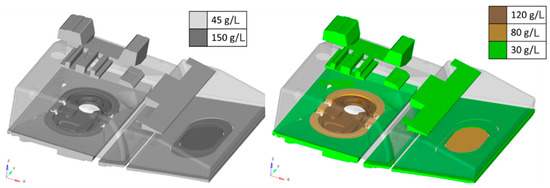
Figure 19.
Comparison between the preliminary foam configuration and the optimized configuration.
The optimized configuration results in the total compression of the lower foams during the drop analysis in order to ensure the maximum absorption of energy and, therefore, mitigates the transmission of the impact load to the storage system.
3. Full Model Results
The analysis of results is aimed at verifying that each subcomponent of the system is compliant with the no-leakage requirement.
The first step conducted has been the numerical energy balance verification in order to confirm the good outcome of the analysis. Figure 20 reports the numerical energies’ time history, showing that the FE model is well defined. The total energy is the sum of the kinetic, internal, hourglass and sliding interface energies. Furthermore, the hourglass energy (related to artificial energy) and the sliding interface energy (related to dissipations in contacts) are below the 2% with respect to the total energy.
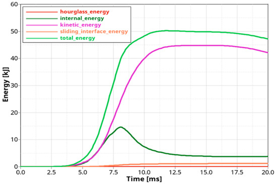
Figure 20.
Numerical energy balance of the wing bay subject to the experimental acceleration pulse.
Figure 21 shows the comparison between the acceleration pulse applied to the wing structure and the numerical acceleration response in six relevant positions of the fuel storage system model: the T-branch of feed, return and vent lines and the probe and the sump plate of the tanks 2A and 2B. The accelerations values are dimensionless with respect to the input pulse peak. All the curves except the one related to Sump 2B are not synchronized with respect to the input pulse. This delay is due to the dynamics of motion since it is imposed by wing structure to the fuel system components through deformable elements (such as the foam blocks and connection systems). Instead, 2B Sump is directly bolted to the access door of the 2B tank, without deformable components; therefore, the acceleration curve is very similar to the input pulse. The T-branches curves show the greatest delay with respect to the input pulse because they are positioned in the upper part of the tank 2A; therefore, they are the last elements of the motion transmission path. Among them, the vent curve shows a higher peak than the others, and this is also related to the dynamics of motion. In fact, the vent T-branch is subject to a relative z-displacement with respect to the wing structure that is higher than the others, as highlighted in Figure 22.
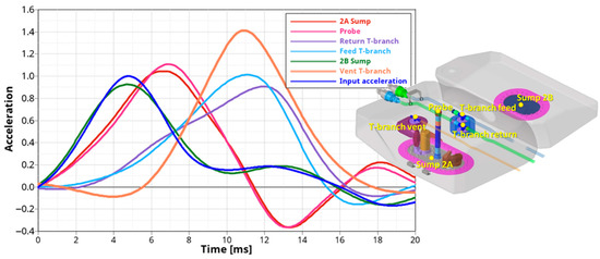
Figure 21.
Acceleration response in 6 relevant location and the input acceleration.
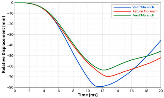
Figure 22.
Relative z-displacement of the t-branches with respect to the wing structure.
Figure 23 shows the dynamics of the fuel storage system over the simulation time in a reference frame jointed to the wing structure. The isometric view of the entire full-scale model is reported on the left, whereas there is a section in XZ the plane on the right that depicts the dynamics response of the components within the tanks (water included). The isometric view highlights that the tanks drop in terms of impact at the lower panel and then rise upward in the rebound phase. The fuel lines (connected to the tank structure by means of flanges) move with the tanks during the entire analysis. From the drop dynamic sequence on the right, it can be noted that the water particles follow the tank’s structure during its deformation from the drop (frames 0 and 1) to the rebound phase (frames 2 and 3) by demonstrating a good simulation of fluid–structure interaction. Furthermore, the foam blocks located between the tanks and the lower panel are crushed completely by absorbing almost the entire impact energy and then they return to their original shapes.
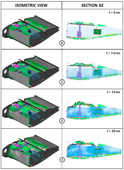
Figure 23.
Global drop dynamic.
By performing the drop analysis in Ls-dyna, it is possible to monitor the stress and strain distributions of each component over the simulation time and to compare the maximum values reached with the material’s ultimate strength in order to verify that no failure occurs in the tank, preventing fuel leakeage. The main cause of the leakage is tank structural failure; therefore, the strain contours of the tanks in both weft and warp directions have been analysed in order to ensure that the maximum values attained are smaller than the one permitted by the material. Figure 24 shows the strain contours in both the orthotropic directions at 9 ms. Such instances correspond to the acceleration peak reported in Figure 3 and to the time at which the maximum strain values are achieved. The maximum value, reached along the weft direction, is about 31%, which is well below the material limits. Thus, there is a large margin of safety.
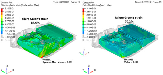
Figure 24.
Strain contour in the warp (left) and weft (right) directions.
The same study is performed for the fuel distribution lines, another potential source of leakage. In addition, the lines are joined to the tanks’ structure by means of metallic or rubber flanges. Any flange separation from the tank results in fuel leakage. The effective plastic strain contour in Figure 25 highlights that the most critical location for the lines is the interface with the wing rib holes. As shown in Figure 26, the contact between these components occurs at about 5 ms (frame 2) due to the clearance between the lines and the holes internal surface; after that, the effective plastic strain increases (frame 3) until reaching the maximum value of about 26.5% at 15 ms (frame 4). This value is smaller than the allowable effective plastic strain of the steel AISI321 AMS5570/MIL-T-8808, which is 35%. Once the maximum is reached, the effective plastic strain remains almost constant up to the end of the simulation as shown in the chart of Figure 27.
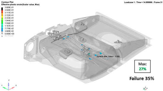
Figure 25.
Distribution lines effective plastic strain at the maximum strain step-time.
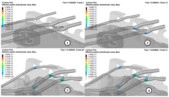
Figure 26.
Impact dynamic between the distribution lines and the rib cut-off.
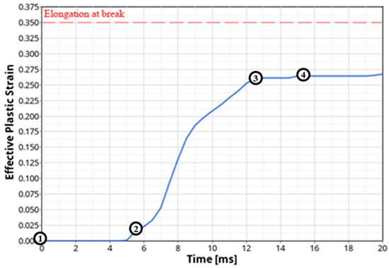
Figure 27.
Effective plastic strain versus time at the most critical location of the distribution lines.
As already discussed, a preliminary study has been carried out with the aim of optimizing the foams in order to minimize weight while ensuring sufficient mechanical crash resistance; therefore, the foam blocks’ configuration shown in Figure 19 has been adopted. Figure 28 shows the maximum compression strain of the lower foam blocks. Almost all the foams reached complete compression and then returned to the original configuration.
Figure 28.
Strain contour of the foam blocks at the initial time and maximum compression time.
4. Conclusions
In the present work, a detailed simulation of the most critical fuel tank bay of a civil Tiltrotor has been presented. The simulation aims at reproducing the scenario of a drop from 50 ft (CS 29.952). The main focus is on the crashworthiness of the tank structure and the fuel lines by also analyzing damage sources coming from the components installed inside the tank (e.g., the components mounted on the sump plates). Moreover, an optimization of the foams, which typically are interposed between the tanks and the surrounding wing structure, has been performed. This optimization activity of the foams was aimed at minimizing the weight of the entire fuel storage system while simultaneously guaranteeing a non-negligible contribution to the absorption of the impact energy. The tank material numerical model and the foam numerical model were validated by experimental tests. The results show that both the tanks and the fuel lines do not reach critical strain values, whereas the optimized foam configuration contributes in a significant way to the absorption of the impact energy. The activity presented in this paper is framed within a building block roadmap with the final aim of having experimentally validated full scale models of the most critical fuel tank bay of the NGCTR-TD.
Author Contributions
Conceptualization, C.S.P., C.P., M.B., S.M., F.D.C., G.L. and L.D.P.; Data curation, V.M.; Investigation, C.S.P., C.P., M.B., S.M., F.D.C., V.M., G.L. and L.D.P.; Methodology, C.S.P., C.P., M.B., S.M., F.D.C., V.M., G.L. and L.D.P.; Project administration, M.B. and L.D.P.; Writing—original draft, C.S.P., C.P., M.B., S.M., F.D.C., V.M., G.L. and L.D.P.; Writing—review & editing, C.S.P., C.P., M.B., S.M., F.D.C., V.M., G.L. and L.D.P. All authors have read and agreed to the published version of the manuscript.
Funding
This research was funded by from the Clean Sky 2 Joint Undertaking under the European Union’s Horizon 2020 research and innovation programme, Grant Agreement number: 738078—DEsign, development, manufacture, testing and Flight qualification of nExt geNeration fuel storage system with aDvanced intEgRated gauging and self-sealing capabilities (DEFENDER).
Institutional Review Board Statement
Not applicable.
Informed Consent Statement
Not applicable.
Acknowledgments
The authors would like to acknowledge Secondo Mona S.p.a. (DIGIFuel Consortium) for the fruitful support.
Conflicts of Interest
The authors declare no conflict of interest.
References
- Fast Rotorcraft, Clean Sky. Available online: https://www.cleansky.eu/fast-rotorcraft-iadp (accessed on 15 September 2021).
- Forecasts of Scheduled Passenger and Freight Traffic, ICAO. Available online: https://www.icao.int/sustainability/pages/eap-fp-forecast-scheduled-passenger-traffic.aspx (accessed on 15 September 2021).
- The Only Way is up: NextGenCTR Takes Shape; Clean Sky. Available online: https://www.cleansky.eu/the-only-way-is-up-nextgenctr-takes-shape (accessed on 15 September 2021).
- Belardo, M.; Beretta, J.; Marano, A.D.; Diodati, G.; Paletta, N.; Di Palma, L. On the preliminary structural design strategy of the wing of the Next Generation Civil Tilt-Rotor Technology Demonstrator. Int. J. Aeronaut. Space Sci. 2021, 22, 613–624. [Google Scholar] [CrossRef]
- Belardo, M.; Marano, A.D.; Beretta, J.; Diodati, G.; Graziano, M.; Capasso, M.; Ariola, P.; Orlando, S.; Di Caprio, F.; Paletta, N.; et al. Wing Structure of the Next-Generation Civil Tiltrotor: From Concept to Preliminary Design. Aerospace 2021, 8, 102. [Google Scholar] [CrossRef]
- Di Palma, L.; Belardo, M.; Di Caprio, F. CLEAN SKY 2 FRC-IADP NextGen Civil Tiltrotor Crashworthiness Approaches; NASA Webinar on eVTOL Crashworthiness. 2021. Available online: https://nari.arc.nasa.gov/crashworthiness (accessed on 15 September 2021).
- Robertson, S.H.; Johnson, N.B.; Hall, D.S.; Rimson, I.J. A Study of Helicopter Crash-Resistant Fuel Systems; DOT/FAA/AR-01/76; U.S. Department of Transportation Federal Aviation Administration: Washington, DC, USA, 2002.
- Jackson, K.; Boitnott, R.; Fasanella, E.L.; Jones, L.E.; Lyle, K. A History of Full-Scale Aircraft and Rotorcraft Crash Testing and Simulation at NASA Langley Research Center; BiblioGov: Columbus, OH, USA, 2013. [Google Scholar]
- Anghileri, M. Crash Behaviour of Helicopter Fuel Tank Structures; ICAS Proceedings: Melbourne, Australia, 1998. [Google Scholar]
- Anghileri, M.; Castelletti, L.-M.L.; Tirelli, M. Fluid-structure interaction of water filled tanks during the impact with the ground. Int. J. Impact Eng. 2005, 31, 235–254. [Google Scholar] [CrossRef]
- Invernizzi, F.; Poggi, S.; Tirelli, M. Helicopter Fuel Tank Crashworthiness: Numerical Approach for the Design; The Pennsylvania State University: State College, PA, USA, 2006. [Google Scholar]
- Luo, C.; Liu, H.; Yang, J.-L.; Liu, K.-X. Simulation and Analysis of Crashworthiness of Fuel Tank for Helicopters. Chin. J. Aeronaut. 2007, 20, 230–235. [Google Scholar] [CrossRef][Green Version]
- Kim, H.-G.; Kim, S. Numerical simulation of crash impact test for fuel cell group of rotorcraft. Int. J. Crashworthiness 2014, 19, 639–652. [Google Scholar] [CrossRef]
- Ramirez, J.B.; Dupas, J. Research on a methodology for flexible fuel tank development. In Proceedings of the 23th Congrès Français de Mécanique, Lille, France, 28 August–1 September 2017. [Google Scholar]
- Yang, X.; Zhang, Z.; Yang, J.; Sun, Y. Fluid-structure interaction analysis of the drop impact test for helicopter fuel tank. SpringerPlus 2016, 5, 1573. [Google Scholar] [CrossRef]
- Smith, M.; Tho, C.-H.; Marimuthu, A.K. Fuel System Drop Test Simulation–Virtual Testing, Bell Helicopters. In Proceedings of the 12th EASA Rotorcraft Symposium, Cologne, Germany, 4–5 December 2018. [Google Scholar]
- Halbout, S.; Vagnot, A. Dynamic Simulation for Bird Strike, Ditching or Fuel tank drop. In Proceedings of the 12th EASA Rotorcraft Symposium, Cologne, Germany, 4–5 December 2018. [Google Scholar]
- Perfetto, D.; Lamanna, G.; Manzo, M.; Chiariello, A.; Di Caprio, F.; Di Palma, L. Numerical and Experimental Investigation on the Energy Absorption Capability of a Full-Scale Composite Fuselage Section. Key Eng. Mater. 2019, 827, 19–24. [Google Scholar] [CrossRef]
- Riccio, A.; Saputo, S.; Sellitto, A.; Russo, A.; Di Caprio, F.; Di Palma, L. An Insight on the Crashworthiness Behavior of a Full-Scale Composite Fuselage Section at Different Impact Angles. Aerospace 2019, 6, 72. [Google Scholar] [CrossRef]
- Di Palma, L.; Di Caprio, F.; Chiariello, A.; Ignarra, M.; Russo, S.; Riccio, A.; De Luca, A.; Caputo, F. Vertical drop test of composite fuselage section of a regional aircraft. AIAA J. 2020, 58, 474–487. [Google Scholar] [CrossRef]
- Riccio, A.; Saputo, S.; Sellitto, A.; Di Caprio, F.; Di Palma, L. A numerical-experimental assessment on a composite fuselage barrel vertical drop test: Induced damage onset and evolution. Compos. Struct. 2020, 248, 112519. [Google Scholar] [CrossRef]
- Certification Specifications for Large Rotorcraft CS-29, CS29; European Aviation Safety Agency Amendment 3; European Aviation Safety Agency: Cologne, Germany, 11 December 2012.
- Caputo, F.; Lamanna, G.; Perfetto, D.; Chiariello, A.; Di Caprio, F.; Di Palma, L. An experimental and numerical crashworthiness study of a full-scale composite fuselage section. AIAA J. 2020, 58, 700–718. [Google Scholar] [CrossRef]
- Livermore Software Technology Corporation (LSTC). Keyword User’s Manual, Volume II: Material Models; Livermore Software Technology Corporation: Livermore, CA, USA, 2017. [Google Scholar]
- Borrvall, T.; Ehle, C.; Stratton, T. A Fabric Material Model with Stress Map Functionality in LS-DYNA. In Proceedings of the 10th European LS-DYNAConference, Würzburg, Germany, 15–17 June 2015. [Google Scholar]
- Vignjevic, R.; Campbell, J. Review of Development of the Smooth Particle Hydrodynamics (SPH) Method. In Predictive Modeling of Dynamic Processes; Springer: Boston, MA, USA, 2009; pp. 367–396. [Google Scholar]
- Giannaros, E.; Kotzakolios, S.; Tsantzalis, S.; Kostopoulos, V.; Campoli, G. Novel simulation of composite material behavior subjected to hyper-velocity impact (HVI) and produced secondary debris by using smoothed-particle-hydrodynamics code (SPH) methodology in LS-DYNA. In Proceedings of the 11th European LS-DYNA conference, Salzburg, Austria, 9–11 May 2017. [Google Scholar]
- Livermore Software Technology Corporation (LSTC). LS-DYNA Theory Manual; Livermore Software Technology Corporation: Livermore, CA, USA, 2006. [Google Scholar]
- Cristillo, D.; Di Caprio, F.; Pezzella, C.; Paciello, C.; Belardo, M.; Di Palma, L. Comparison of numerical models for the prediction of bladder tank crashworthiness. In MEDYNA2020, Proceedings of 3rd Euro-Mediterranean Conference on Structural Dynamics and Vibroacoustics, Napoli, Italy, 17–19 February 2020; De Rosa, S., Franco, F., Guida, M., Marulo, F., Petrone, G., Eds.; Mare Group: Ossona, Italy, 2020; ISBN 9788890648465. [Google Scholar]
- ARPRO. Dynamic Compressive Properties. Available online: https://www.arpro.com/contentassets/84d1d4035d5549c8a038a089e63bd21f/arpro-dynamic-compressive-properties-en.pdf (accessed on 15 September 2021).


Publisher’s Note: MDPI stays neutral with regard to jurisdictional claims in published maps and institutional affiliations. |
© 2021 by the authors. Licensee MDPI, Basel, Switzerland. This article is an open access article distributed under the terms and conditions of the Creative Commons Attribution (CC BY) license (https://creativecommons.org/licenses/by/4.0/).