Recent Advances on the Design Automation for Performance-Optimized Fiber Reinforced Polymer Composite Components


School of Mechanical and Aerospace Engineering, Nanyang Technological University, 50, Nanyang Avenue, Singapore 639798, Singapore
*
Authors to whom correspondence should be addressed.
J. Compos. Sci. 2020, 4(2), 61; https://doi.org/10.3390/jcs4020061
Submission received: 4 May 2020
/
Revised: 29 May 2020
/
Accepted: 29 May 2020
/
Published: 29 May 2020
Abstract
:Advanced manufacturing techniques, such as automated fiber placement and additive manufacturing enables the fabrication of fiber-reinforced polymer composite components with customized material and structural configurations. In order to take advantage of this customizability, the design process for fiber-reinforced polymer composite components needs to be improved. Machine learning methods have been identified as potential techniques capable of handling the complexity of the design problem. In this review, the applications of machine learning methods in various aspects of structural component design are discussed. They include studies on microstructure-based material design, applications of machine learning models in stress analysis, and topology optimization of fiber-reinforced polymer composites. A design automation framework for performance-optimized fiber-reinforced polymer composite components is also proposed. The proposed framework aims to provide a comprehensive and efficient approach for the design and optimization of fiber-reinforced polymer composite components. The challenges in building the models required for the proposed framework are also discussed briefly.
1. Introduction
Fiber-reinforced polymer (FRP) composites are widely used in the aerospace industry and are becoming more popular in many other fields such as sports, automobile, construction, marine, and offshore [1,2,3,4,5,6]. Besides having very high specific strength, another advantage of FRP composites is their customizability. Advancements in manufacturing technology such as automated fiber placement (AFP) and additive manufacturing (AM) has allowed for increased freedom in designing FRP composites structures. Also, new material formulations have introduced more options to tailor FRP composites to various requirements. The enhanced design space for FRP composites has called for improvements to the conventional design workflow for FRP composite structures so that the customizability of FRP composites can be fully utilized [7].
On the other hand, the emergence of high-speed graphic processing units (GPUs) has greatly accelerated the development of artificial intelligence (AI) and, in particular, deep learning (DL) technology [8]. DL is a type of machine learning (ML) method that utilizes a large multi-layered learning structure. Compared to conventional ML methods, DL has the advantage of requiring very little human engineering in designing the learning process. Also, DL is very effective in solving problems involving a large number of variables [8,9].
For FRP composite structures, many researchers and engineers have used computational tools such as finite element analysis (FEA) in computer-aided design (CAD) processes. As the design space for FRP composites expands, CAD processes need to be improved to realize the full potential of FRP composites. In this paper, the application of AI and DL methods in the design automation of FRP composites is discussed. Some of the areas in FRP design where DL technologies can be impactful are highlighted. An automated design framework for FRP composite components with optimized performances is also presented.
2. Background
The backgrounds of the computer-aided manufacturing (CAM) techniques for FRP composite components as well as AI technologies (including ML and DL methods) are presented. The manufacturing and modeling methods discussed here combine to make up the technologies required for the design automation of performance-optimized FRP composite components.
2.1. Computer-Aided Manufacturing
In CAM of FRP composites, the FRP composite component is designed and programmed onto a machine using a software tool wherein the program then controls and guides the machine to fabricate that component. AFP and AM are such CAM processes, which offer high levels of flexibility in the FRP composites configuration.
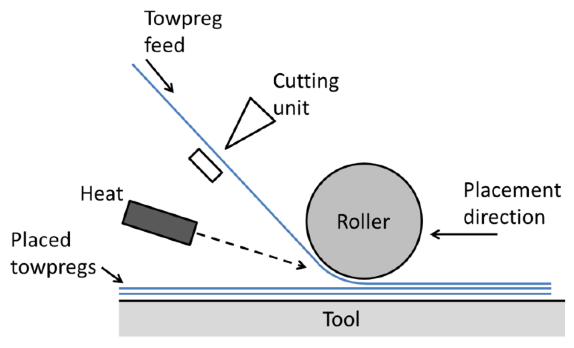
In the AFP process, FRP towpregs are laid in the desired orientation using a robot arm. A schematic of the AFP process is shown in Figure 1. AFP produces laminates with more precise and consistent fiber orientation compared to conventional manual processes. The towpregs can be placed in straight strips or a curved fashion. AFP processes have been used to fabricate variable stiffness FRP laminates, i.e., laminates with curvilinear configurations, to improve the laminate’s buckling performance [10]. Factors affecting the quality of components fabricated using AFP include the processing temperature, the type of heat source, the fiber placement rate and the compaction pressure [11,12].
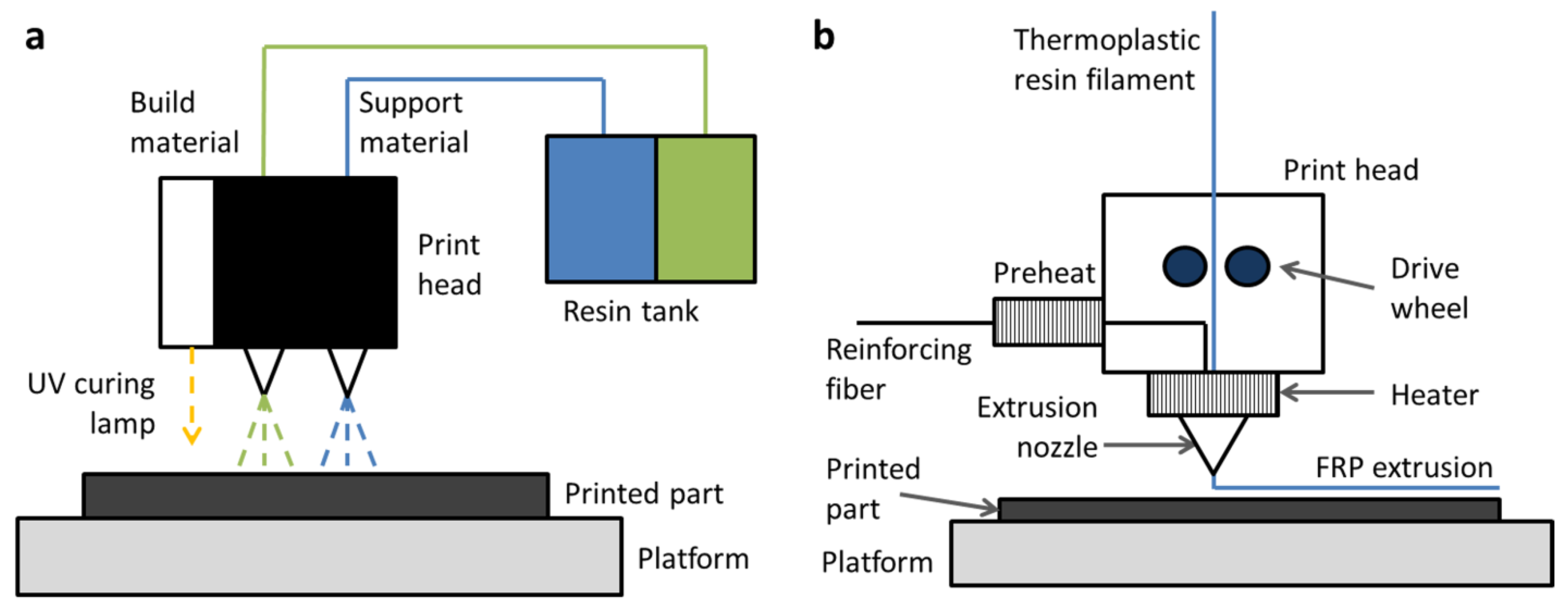
The AM or 3D printing process is a manufacturing process where materials such as metals and polymers are added point by point to form a 3D component. The raw materials used in AM can be solid, liquid, or in powder form [13]. Advancements in AM have greatly improved the precision of the process and expanded the range of materials that can be used. Fidan et al. gave an overview of various materials used to produce FRP composites through AM [14]. The important processing parameters for AM include processing temperature, printing orientation and printing speed [15,16]. Multiscale composite components have been successfully fabricated using advanced AM processes such as the voxel-based placement of polymers by material jetting [7]. For composite components with continuous fiber reinforcement, the fused deposition modeling (FDM) method can be used as well [17]. The material jetting and FDM methods are shown in Figure 2. Reviews of AM processes for FRP composites are given by Wang et al. [18] as well as Parandoush and Lin [19].
AFP and AM processes can be used to produce FRP composite components with varying fiber orientation within and across individual layers. This allows the fibers (short or continuous) to be better oriented in the load directions, thus increasing the load-carrying capability of the FRP composite component [2,20]. The stress distribution in the FRP laminates can also be changed, leading to a higher buckling load in variable stiffness laminates [21]. However, the increased flexibility also resulted in greater complexity in the performance optimization process for the FRP composite components. Consequently, designing performance-optimized FRP composite components becomes very time consuming using conventional CAD tools. In order to increase the efficiency of the design process, the incorporation of AI technology in the CAD tools is proposed. The background of AI and some of its applications are discussed next.
2.2. Artificial Intelligence
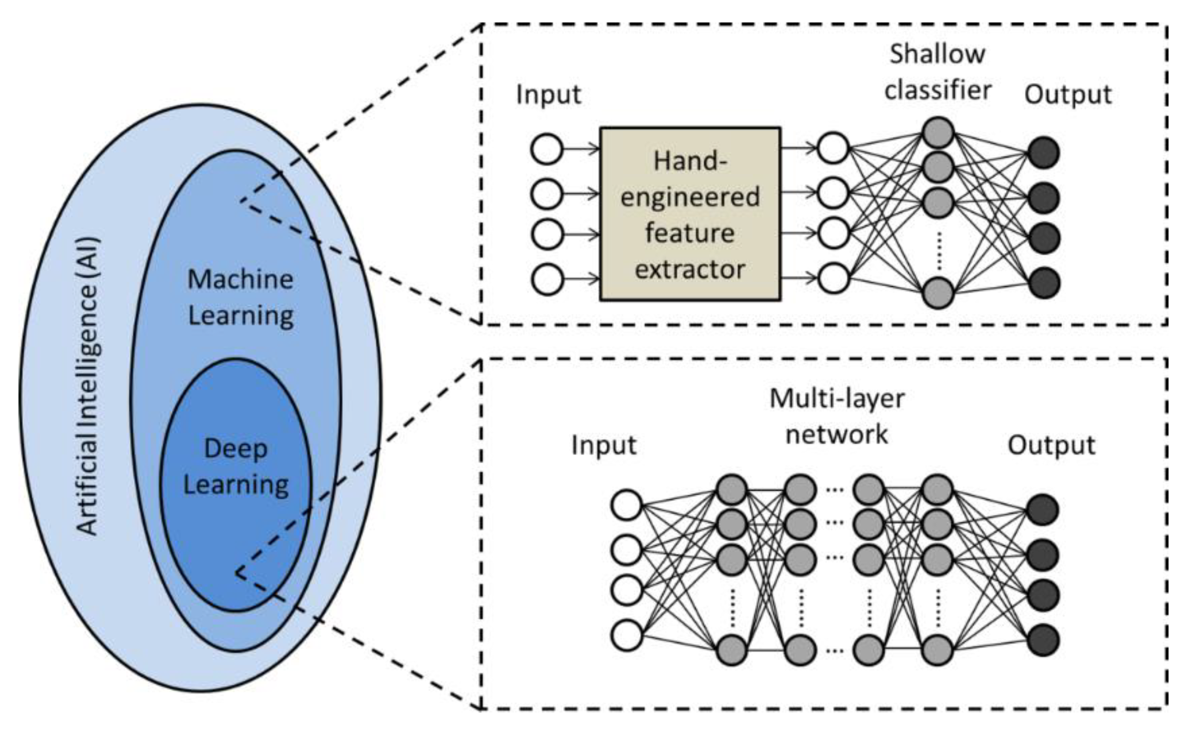
AI can be defined as “the study of the design of intelligent agents”, where an intelligent agent is “a system that acts intelligently” [22]. ML is the technology of using a learning algorithm and data to solve problems. The learning can be in the form of supervised learning, unsupervised learning, or reinforcement learning [23,24]. Conventional ML methods are mainly supervised learning with shallow classifiers that take inputs from hand-engineered feature extractors [8,9]. Conventional ML methods achieved some success in simpler tasks, but for more complicated problems, building the feature extractors became very difficult. One of the main challenges is termed the “selectivity-invariance dilemma” where the algorithm needs to differentiate between features that are important and unimportant [8].
In recent years, DL models have been shown to be effective in overcoming the selectivity-invariance dilemma. Compared to conventional ML models, the formulation of DL models generally requires very little human inference [8,9]. DL models have a multi-layered architecture, with each layer having different functions such as convolution and pooling. The resulting multi-layer representation abstraction in DL models can produce representations with both increased selectivity and invariance from its inputs, thus solving the selectivity-invariance dilemma [8]. A review of DL technology is given by LeCun et al. [8]. Figure 3 shows the relationship between AI, ML, and DL. For the purpose of this paper, distinguishing DL from conventional ML methods is not important, thus ML is used to refer to both conventional ML and DL methods.
Many different types of ML models (deep and shallow) have been developed for different kinds of problems. They include various neural networks (NNs) such as convolutional NNs (CNNs) and recurrent NNs (RNNs), Restricted Boltzmann Machine (RBM) and its variants, auto encoders and its variants, as well as generative models such as the Generative Adversarial Network (GAN) [9,25]. Descriptions of some of the different types of models and a comparison can be found in [9] by Wang et al. It is important to choose a suitable model for the problem being considered.
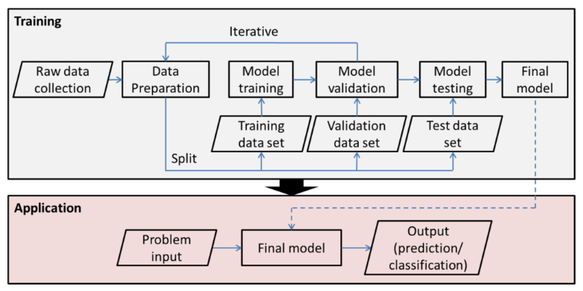
In general, the implementation of ML models involves a training phase before the models can be put to use. Figure 4 shows a typical implementation process for supervised ML. Data consisting of an input and target output pairs are required for the supervised training. The data are pre-processed (filtering, normalization, etc.) and split into training, validation, and testing data sets. A common ratio for the data split is 60% training, 10% validation, and 30% testing [26]. For the iterative cycle of model training and validation, the k-fold cross-validation and bootstrapping methods can be used [23,26]. The model is trained by minimizing an error or loss function, L(w), which measures the difference between the current model output (computed with the current set of internal adjustable parameters or weights, w) and the target output. The minimization of the loss function is done by adjusting the weights following the stochastic gradient descent procedure. For multi-layered networks, backpropagation is used to calculate the gradients in the minimization process [8,26]. After training and validation, the model is further tested on a test data set which has not been seen by the model. If the model produces satisfactory results on the test data set, then it is ready to be applied to real-world problems. The implementation of ML models and considerations in the training phase (e.g., learning rate, overfitting) are also detailed in [23,26].
For unsupervised and reinforcement learning, the ML model also needs to be trained but the training is carried out differently. For unsupervised learning, the training data contain only the inputs. The unsupervised ML model is then trained to learn the structure of the data [24]. The optimization procedure and the loss function used depend on the unsupervised learning method. For example, auto encoders can be optimized based on the least-squares loss [9,23], while the generative adversarial network (GAN) is trained based on competition between the generator and discriminator networks [25,27]. For reinforcement learning, the ML model is trained to make decisions based on the state of an environment. The learning is carried out using reward systems where the model learns to make decisions to maximize the rewards received [23,24].
ML has been used in many applications including face recognition, content filtering, and speech recognition [8]. Advanced AI systems trained with reinforcement learning methods, such as the OpenAI Five [28] and AlphaGo [29], have beaten their human opponents in games requiring strategic thinking. Currently, there are various open-source software on ML available, such as Caffe [30] and TensorFlow [31]. A comparison of the different software is presented by Angermueller et al. [26] and Wang et al. [9]. The availability of ML software has helped to accelerate studies on various aspects of ML.
3. Design of FRP Composite Components
The design process for FRP composite components includes material selection and topology optimization coupled with stress analysis. Studies on the different aspects of FRP composite components design are discussed in this section. Areas, where ML techniques have been applied, are also highlighted.
3.1. Material Design and Selection
As demands for more advanced material systems grow, improvements to the conventional materials design and selection process are needed. To this end, the integrated computational materials engineering (ICME) approach has been introduced [32,33]. ICME is “the integration of materials information, represented in computational tools, with engineering product performance analysis and manufacturing-process simulation” [33]. A review of the software tools developed and material databases established for the advancement of data-driven ICME is given by Wang et al. [34].
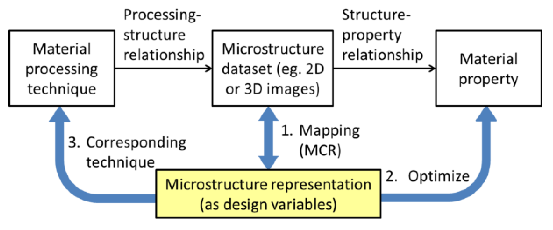
Figure 5 shows the general framework for material design following the ICME approach. The manufacturing process affects the microstructure of the material (processing-structure relationship), which in turn determines the material properties (structure-property relationship). If the structure-property relationship can be established, the data on the material microstructure can then be used to optimize for the desired material property (e.g., strength, toughness). However, using raw microstructure data for material design is difficult due to the large number of variables involved [35]. Therefore, the raw data need to be mapped to a set of microstructure representations to reduce the design space. This mapping is termed microstructure characterization and reconstruction (MCR) [36]. The reduced number of variables can then be used in the optimization of the material design. Subsequently, the microstructure representations can be linked back to their corresponding material processing techniques, which are required to produce the designed material.
MCR techniques can be divided into two categories: (i) correlation function-based methods, and (ii) descriptor-based methods [37,38]. Xu et al. investigated a descriptor-based method for the reconstruction of 3D microstructures from 2D images [37]. Polymer nanocomposites were used as examples to illustrate the proposed method. The microstructure was characterized based on composition, dispersion, and geometry. The accuracy of the method was demonstrated using case studies of nanoparticle filled polymer composites (artificial and real). However, choosing the characterization criteria for the method requires extensive knowledge and experience on the subject. For complex material systems, designing such criteria is difficult.
Xu et al. later proposed an improved MCR method utilizing ML techniques [38]. The researchers first gathered a large set of descriptors from studies on a variety of materials including alloy, polymer nanocomposites, fiber composites, ceramic composites, etc. The descriptors were then reduced to a set of key microstructure descriptors through four steps: (i) descriptor-descriptor correlation, (ii) correlation function-based supervised learning, (iii) property-based supervised learning, and (iv) optimization-based selection. The selection criteria for the descriptors include independence and impact on the material property. ML-based models were used in all the four steps of the method. Xu et al. applied the ML-based method to the case study of a nanocomposite (elastomer with carbon black nano-fillers) for tire applications. The damping properties of the nanocomposite in the low, normal and high frequency domains, denoted L, P, H respectively, were of interest. The design is framed as an optimization problem to minimize L, maximize P and minimize H. Xu et al. reported that using key descriptors identified through ML resulted in microstructures which gave lower L, higher P and lower H compared to descriptors identified based on empirical or expert knowledge.
Another study on ML-based MCR was conducted by Cang et al. [35]. The researchers proposed an ML model consisting of RBM layers and three convoluted RBM (CRBM) layers. The model can be used for feature extraction (reduce the raw microstructure image to a small representative image) as well as reconstruction (rebuild the material microstructure from the representative image). Cang et al. demonstrated the effectiveness of the model using four different material systems and their critical strength values. The critical strength values were found to be statistically the same after the feature extraction and reconstruction process. This showed that the ML model successfully reduced the design space (200 × 200 image to 30-dimensional binary vector) without losing important information. However, the proposed model can only process images of a fixed size and is not scalable, as noted by the authors. They also recommended incorporating physics-based rules to the model to improve the feature extraction and reconstruction results.
A methodology encompassing the full process of microstructural material design has been presented by Yang et al. [36]. The MCR method used was based on GANs. The deep network architecture of the GANs minimizes the information loss in producing the microstructure representation, or latent variables. The dimensionality of the latent variables can be set according to the design problem. However, the authors noted that the dimensionality cannot be too small as it will make training the GAN very difficult. For the material design using the latent variables, GP-Hedge Bayesian optimization was applied to obtain the desired material property [39]. The optimization process was coupled with the Gaussian process metamodeling to reduce the number of material property evaluations (computationally costly physical simulations) performed. Yang et al. demonstrated the application of the methodology in a case study of microstructural material design for optimizing optical absorption. A synthetic dataset was used in the case study. Using the proposed methodology, the optimized microstructure with 17.2% increased optical absorption was determined. The authors also highlighted the scalability and transferability of the proposed method.
Liu et al. developed a deep material network to formulate the representative volume element (RVE) for dual-phase heterogeneous materials [40]. The nodes/building blocks of the material network were defined based on analytical stress-strain relation. This results in the physics of the material being retained in the deep material network. Several methods to optimize the training process of the material network were described. They include using data from numerical simulations as opposed to experimental data, performing model compression (e.g., nodal deletion, subtree merging), etc. The authors reported that the deep material network was able to simulate various material responses accurately, including nonlinear history-dependent plasticity and finite-strain hyperelasticity under large deformation [40]. The proposed model provides a link from the material microstructure to the meso-scale mechanical response of the material (structure-property relationship).
Behnood and Golafshani used ML models to predict the mechanical properties of concrete mixtures containing waste foundry sand (WFS) [41]. In their study, the authors used the M5P model, which is a type of decision tree. The inputs to the M5P model consisted of descriptors, such as WFS to cement ratio, water to cement ratio and coarse aggregate to cement ratio. These descriptors were determined from expert knowledge on the topic. Data reported in the literature were used to train the M5P model. The models were trained to predict the compressive strength, modulus of elasticity, flexural strength and splitting tensile strength of the concrete mixtures of interest. The researchers tested the predictions using several error measures (such as root mean square error) and found them to be satisfactory.
The research group also studied another ML approach termed multi-objective artificial neural network (MOANN) to predict the compressive strength of concrete mixtures [42]. For the MOANN model, the architecture of the artificial NNs (ANNs), such as the number of hidden layers and nodes, were optimized using a multi-objective salp swarm algorithm (MOSSA). Similar to [41], descriptors identified empirically were used as inputs for the model, and data from the literature were used for training. The researchers found that ANNs with more complex architectures gave better predictions, but the increase in accuracy becomes smaller as the ANNs become more complex. The optimized model, termed ANN-16, had a 7-5-4-1 architecture. The researchers compared the predictions given by the ANN-16 model to those of the M5P model and found that the ANN-16 model was more accurate (50% lower mean abosolute percentage error). However, in both studies [41,42], the models relied on descriptors identified empirically. Further optimization on the choice of descriptors could improve the performance of the models.
For FRP composites, the microstructures are affected by factors such as the choice of matrix and fiber, addition of micro- and nano-fillers, fiber orientation, manufacturing process, etc. Following the framework shown in Figure 5, the mechanical properties of the FRP composite can be derived from the microstructure data. The derived properties can then be used for the stress analysis of the structure, which will be discussed next.
3.2. Stress Analysis
Finite element (FE) simulations are widely used to perform stress analysis of FRP composites. For a complete analysis of FRP composites, the pre-failure, onset of failure, and post-failure behaviors need to be modeled. Many failure criteria [43] and damage models [44,45,46] have been proposed for predictions of failure and post-failure mechanical responses. Depending on the loading conditions and working environment, other aspects such as nonlinear shear deformations [47,48] need to be considered as well.
Ghaboussi et al. used the load-displacement response of a structure to train NN material model that can be used in FE simulations [49]. The training method was termed “auto progressive training”. The training involves two phases: (i) the forward analysis phase and (ii) the training phase. In the first phase, a load increment is applied and the corresponding strains are calculated using the NN model. Displacement corrections are applied, if necessary, to achieve the convergence tolerance set. When the tolerance requirement is met, the stress-strain pair is then stored as a training case. The training cases are then used in the training phase to update the weights of the NN model. Also, the NN model used has an adaptive architecture, where additional nodes can be added to the hidden layers if required. Using the analysis of an FRP composite plate with an open hole as an example, the authors showed that the NN model can predict the stress-strain relationship of FRP composites affected by the damage. The study showed that ML methods can be used to formulate material models with complex failure modes and stress-strain relationships.
Another research group studied the evolutionary polynomial regression (EPR) approach to develop material models for FE simulations [50,51]. EPR is a hybrid method which “uses a genetic algorithm to find the form of polynomial expressions and least-squares optimization to find the values for the constants in the expression” [52]. The EPR-based material model was self-trained based on the method described by Ghaboussi et al. [49]. In contrast to the NN model, the EPR-based model gives mathematical expressions linking the inputs to the outputs. This allows researchers to gain a better understanding of the stress-strain constitutional model [50,51].
Kirchdoerfer and Ortiz detailed a data-driven approach to computational mechanics [53]. The proposed data-driven solver uses experimental data directly to calculate the mechanical response of a structure while satisfying the relevant constraints and conservation laws. This circumvents the need for the formulation of a material model, thus avoiding errors due to approximations in the material model. Using the proposed method, the computation is framed as a constrained minimization problem. The problem can then be solved iteratively or using ML methods. The data-driven computational mechanics approach was later expanded on by Nguyen and Keip to include considerations for problems with large deformations [54].
Oishi and Yagawa studied the application of deep neural networks (DNNs) for the computation of numerical quadratures in FE analysis [55]. The authors identified two aspects of numerical quadratures, which can be improved using DNNs: (i) the number of integration points, and (ii) the numerical quadrature parameters for the element stiffness matrix. Separate DNN modules were trained to optimize the two aspects. As a result, the accuracy of the numerical quadrature was improved compared to the conventional Gauss-Legendre method, while the computational resources required are reduced by minimizing the number of integration points.
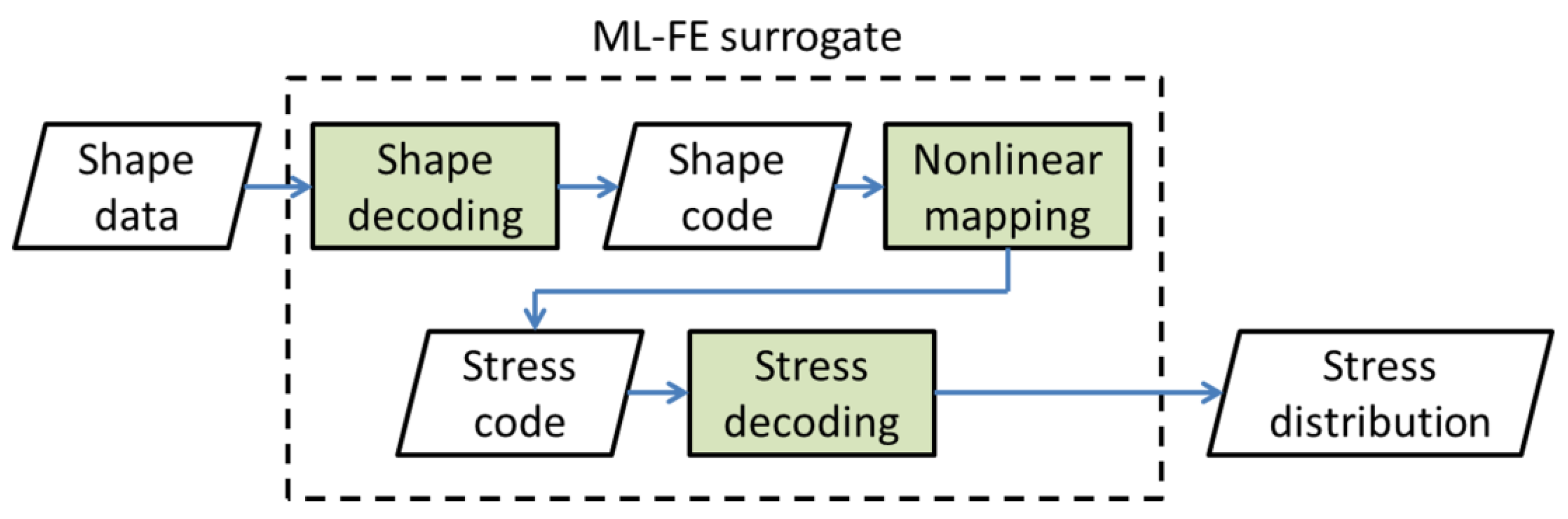
Liang et al. used DNNs to perform mechanical stress analysis in place of FE simulations for applications in biomechanics [56]. The researchers developed an ML model consisting of three modules with different functions: (i) shape decoding, (ii) nonlinear mapping, and (iii) stress decoding. The ML model was referred to as an “ML-FE surrogate” [56]. The model takes shape data as input and produces the corresponding stress distribution as output (Figure 6). The shape and stress codes are representations in the form of 1D vectors. A combination of supervised and unsupervised learning was employed. The researchers reported that the stress analysis results from the ML model are very similar to those obtained using FE simulations, with average errors below 1%. Moreover, using the ML model was reported to be much faster compared to FE simulations. Stress calculations that would take about 30 min to complete in FE simulations can be performed within 1 s using the trained ML model.
Capuano and Rimoli also studied the surrogate modeling approach using ML techniques for stress analysis [57]. The authors’ approach, termed “smart finite element”, involved using data from FE simulations to train the ML-based surrogate model. Similar to the study by Liang et al. [56], the surrogate model provided direct relationships between the inputs and outputs of the elements, thus negating the need for numerical iterations. Capuano and Rimoli also demonstrated two ways to improve the surrogate modeling approach. Firstly, a rigid body movement can be ignored to reduce the training data size for the ML model. Secondly, the principles of equilibrium can be used to improve the accuracy of the model.
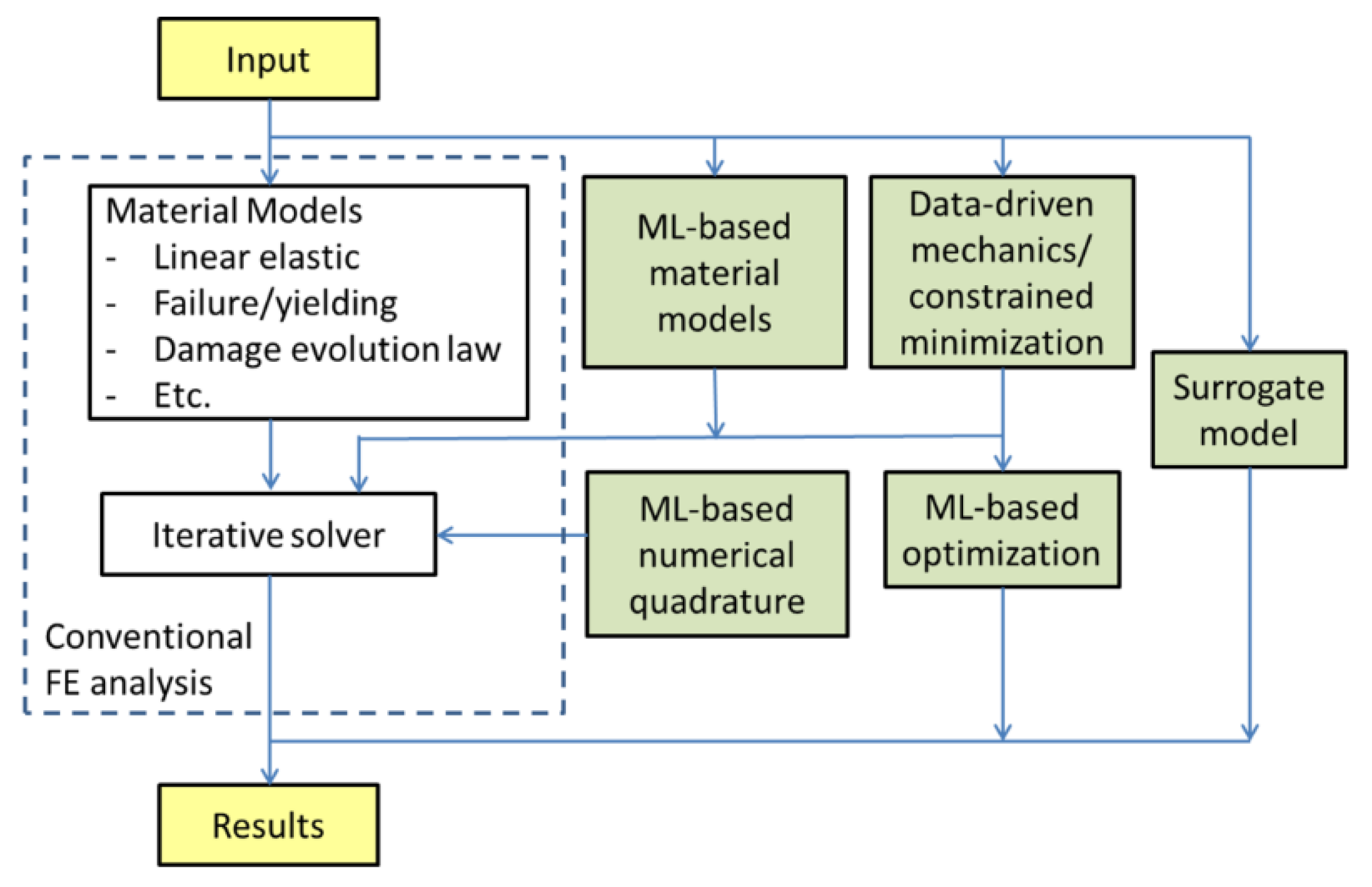
Figure 7 shows the various ML-based approaches for stress analysis that have been studied by researchers. In particular, studies on ML-based surrogate models [56,57] have proven the feasibility of using ML networks as substitutes for FE simulations for stress analysis. The short computation time required makes the ML approach very useful for the design phase of composite structures.
3.3. Topology Optimization
Topology optimization is a design tool that can be used to determine the optimal material layout within a design space, with specified boundary conditions, in order to maximize the performance of the structure. Besides optimizing for high stiffness and low weight [7,20,58], studies have also been carried out to optimize for other performance measures such as post-buckling mechanical response [59] and out-of-plane crushing [60]. Density-based topology optimization methods such as solid isotropic material with a penalty (SIMP) and rational approximation of material properties (RAMP) are widely used by engineers and researchers [61,62]. Other optimization methods include level-set, topology derivative, evolutionary, and phase-field approaches. A review and comparison of the different methods have been given by Sigmund and Maute [63].
For the topology optimization of continuous FRP composites, the fiber orientation and layer thickness need to be taken into consideration. Zhou et al. presented a multi-component topology optimization (MTO) method which generates designs for multi-component composite structure [64]. The multi-component designs can be materialized easily using manufacturing techniques such as AFP. The material orientation was determined at each design point to allow for curvilinear FRP configurations. Esposito et al. proposed a mixed strain- and stress-based topology optimization method for determining the optimal fiber orientation in FRP laminates [20]. The laminate shape was not changed in the optimization process. The authors noted a “dual behavior” resulting from the optimization where the fiber distribution design depended on the type of boundary conditions employed (force or displacement). Yang et al. investigated the use of design representation methods to reduce the dimensionality of the optimization of multi-component, multi-layer composite structures [65]. The authors proposed a method using partial least squares structural equation modeling (PLS-SEM) to identify non-critical parameters or variables to reduce the design space.
For advanced material systems, the material microstructure will also impact the structural performance. Boddeti et al. fixed the microstructure to one configuration in the topology optimization of short fiber-reinforced composite components [7]. This allows the optimization process to be completed faster and ensures that the resulting structure can be manufactured easily, but limits the design options. Rodrigues et al. proposed a multiscale topology optimization method where the microstructure is optimized at each macroscale finite element [66]. However, the method is computationally expensive, especially for large complex systems, and it neglects the scale effect [61,67]. Sivapuram et al. detailed a method to decompose the multiscale optimization into linearized problems [67]. This allows the optimization problem to be solved using parallel computing, thus accelerating the process. Du et al. proposed a connectivity index function to improve the connectivity between microstructures in multiscale topology optimization [68]. The authors reported that the connectivity index applied as an additional constraint did not negatively affect the optimized design.
Another aspect of FRP composite component design is manufacturing constraints. Manufacturing constraints such as the resolution of AM systems and the maximum towpreg curvature of AFP systems can lead to structural and performance discrepancies between the optimized design and the manufactured component [20,69]. Morris et al. proposed using multivariate joint probability distributions to model the manufacturing variations and incorporate them into a Bayesian Network Classifier (BNC) for the optimization process [69]. The authors noted that care needs to be taken for the characterization process to quantify the manufacturing variations. Zhou and Saitou also studied the inclusion of manufacturing constraints into the topology optimization process [70]. The multi-objective genetic algorithm (MOGA) was used with the Kriging-interpolated level-set (KLS) method to reduce the computation time required. The data on the manufacturing constraint were generated through numerical process simulation. The MOGA can produce component designs that are easier to fabricate, albeit with some loss in mechanical performance.
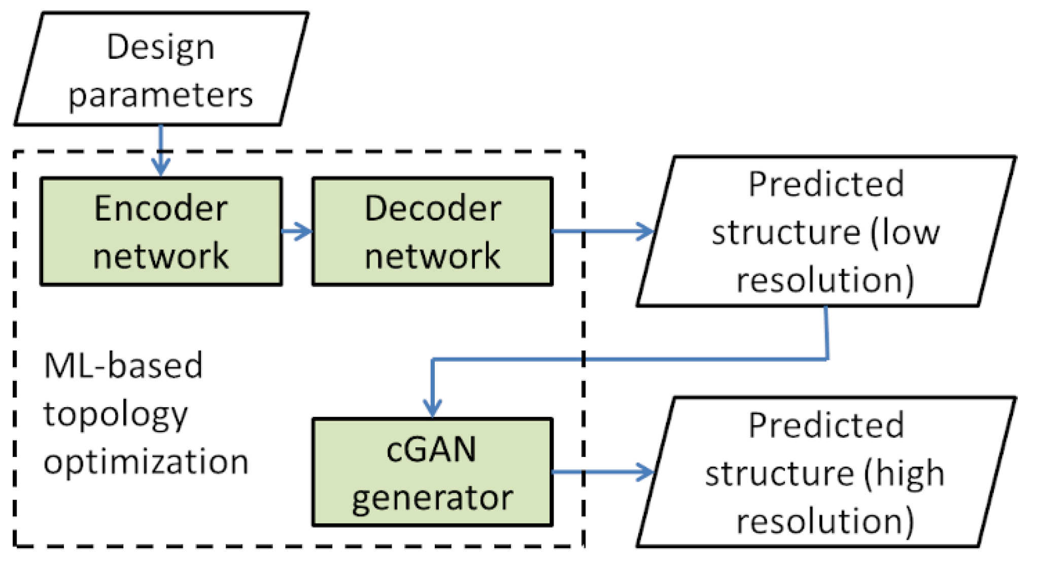
An ML method for topology optimization was proposed in a recent study by Yu et al. [25]. The ML method consists of two stages/modules, namely a CNN-based encoder and a decoder network and a conditional GAN (cGAN) generator. The encoder and decoder network takes in the design domain, parameters, and constraints as input and outputs the optimized structure at low resolution. The low-resolution structure is then up-scaled to higher resolution using the cGAN generator. A schematic of the ML-based topology optimization method is shown in Figure 8.
The performance of the ML method proposed by Yu et al. [25] is summarized in Table 1. Although a training phase is required for the ML method, the trained ML model can greatly reduce the computational time required for topology optimization as it does not require iterative computations (0.014 s for the ML method compared to 22.7 s for existing topology optimization code). The authors also showed that the ML method can give good predictions in most cases. However, the ML model predicted structures containing disconnections in 3.41% of the test cases. This is because structural continuity was not considered in the ML model. Further improvements to the ML method are required to improve its performance and expand its application to more complex problems (e.g., from 2D to 3D structures, a larger variety of boundary conditions).
In another recent study, Hamel et al. used ML-based methods for the design of active composite structures [71]. The active composite is made of an active material and a passive material. The active material responds to the environment and causes the composite structure to change shape, while the passive material does not respond. Hamel et al. used an evolutionary algorithm (EA) to determine the material layout of the composite within a fixed beam geometry. The layout is optimized such that the structure deforms to a target shape when the active composite is stimulated. An EA was chosen because the optimization process using EA involves randomization which makes it suitable for problems with material nonlinearities. FE simulations were used to determine the stimulated shapes from the material layouts produced during the evolutionary process. Using the EA, the authors were successful in obtaining the material layouts corresponding to the sinusoidal and parabolic target shapes. The errors based on deformation were reported to be 4% and below. Besides this, it was also shown that the method can handle multi-objective problems. Hamel et al. noted that material layouts obtained were non-intuitive, thus validating the need to use ML models.
Topology optimization is a powerful tool for the design of components with optimal performances. Many ongoing studies are being carried out on the topic to further improve various aspects of the optimization process.
4. Proposed Automated Design Framework
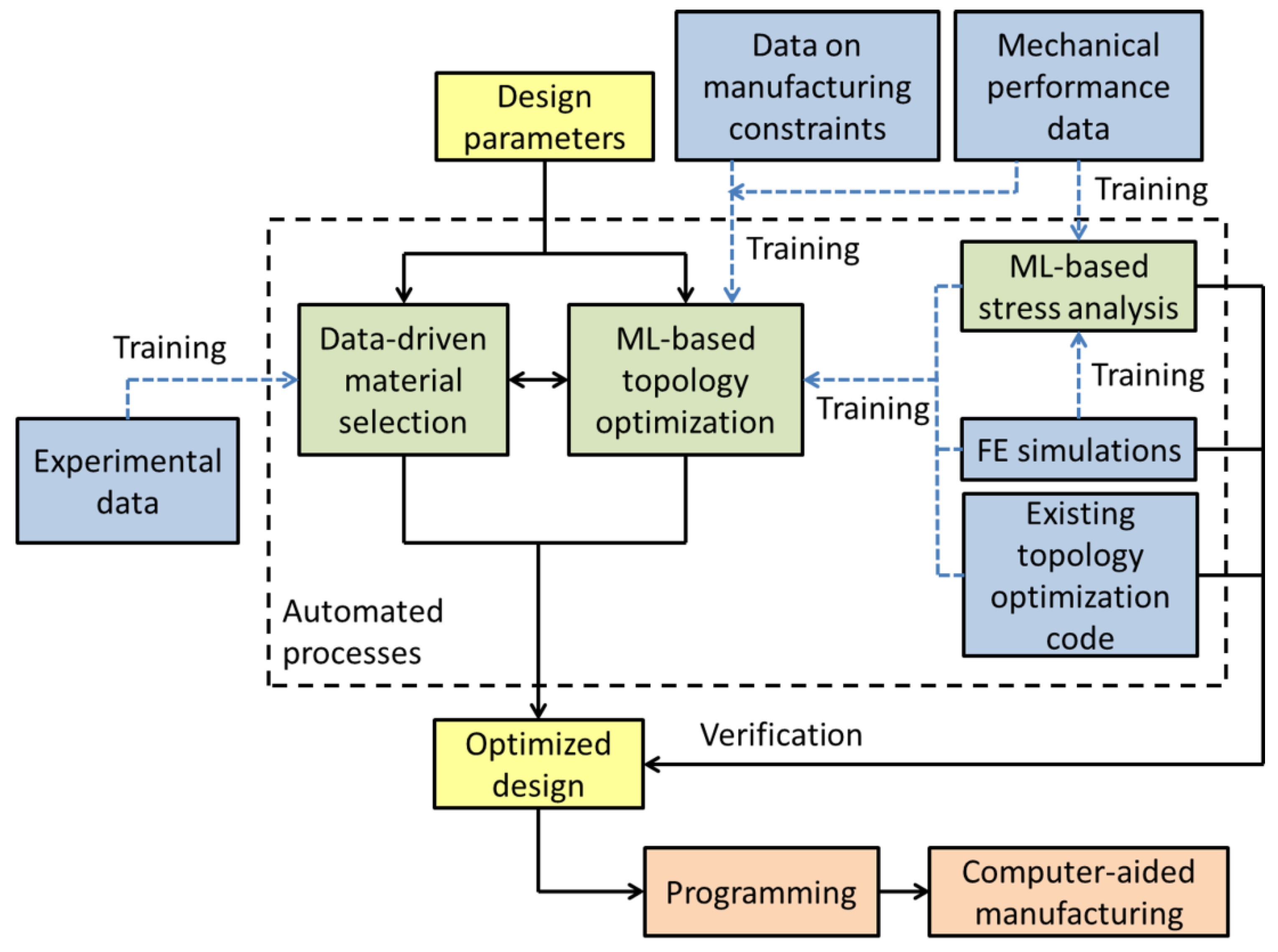
An automated design framework for FRP composite components as shown in Figure 9 is proposed. The framework aims to provide an efficient design workflow for the design of FRP composite components with optimized performance.
The automated design process utilizes data-driven and ML-based methods extensively. For material selection, the ICME approach (Figure 5) is adopted. The data-driven material selection module provides a connection between the microstructure and the material properties for advanced material systems. The material properties can then be used in the ML-based topology optimization module to produce the optimized design. ML techniques are used in the optimization to reduce the number of computational iterations required for the process.
For the training of the design modules, experimental data including microstructure images, manufacturing constraints, and mechanical performance are required. Besides experimental data, numerical simulation results can also be used for the training of the topology optimization module. ML-based stress analysis (such as those in [56,57]) can be used to generate training data for the optimization module efficiently. The self-learning approach [49,50] can be applied to the training of the ML-based stress analysis and topology optimization modules, thus partially automating the training process. The topology optimization module outputs an optimized design which can be realized using CAM such as AFP or AM.
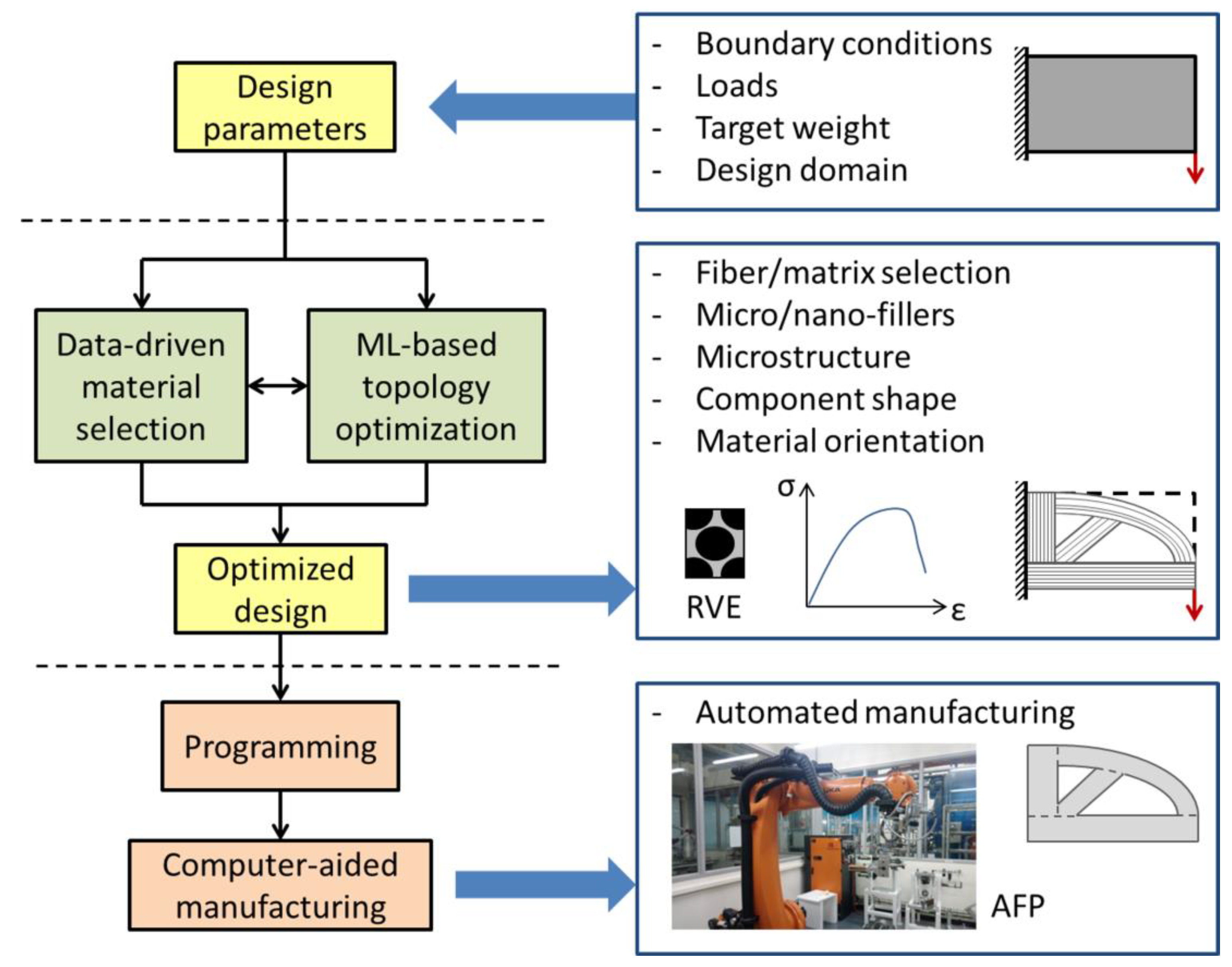
The application of the automated design framework is illustrated in Figure 10 using the optimization of a single load cantilever beam as an example. The design parameters include boundary conditions, loads, target weight, and the design domain. The parameters are the inputs to the data-driven material selection and ML-based topology optimization modules. Based on the loading condition and target weight, the constituent materials, including any micro- or nano-fillers, for the FRP composite component are determined. The material selection module derives the FRP material properties from the material microstructure (e.g., through RVE formulation) and feeds it to the topology optimization module. Topology optimization is performed to determine the geometry and material orientation of the FRP composite component. The material selection and topology optimization modules output an optimized design meeting the design requirements. The design is programmed for the relevant CAM process to fabricate the performance-optimized FRP composite component. The programming process is not trivial and requires some engineering input. For example, depending on the performance desired, the AFP process can be done with towpregs overlapping each other or with small gaps between towpregs. For the latter configuration, the laying pattern needs to be staggered between layers to avoid superposition of the gaps [20].
The automated design framework aims to offer an end-to-end solution for designing FRP composite components. The use of computational methods in the design phase can minimize the number of experimental tests needed to be carried out, and thus also reduce material wastage. Topology optimization can produce designs for FRP composite components with optimized structural behavior, leading to advantages such as reduced weight. Also, the application of ML-based methods in the proposed framework can shorten the time required for the design cycle compared to using conventional computational methods requiring iterative calculations.
Concerns and challenges in implementing the automated design framework are:
- The design modules need to be able to handle a wide variety of materials, loading conditions, performance objectives, manufacturing constraints, and so on. In order to achieve this, the size of the ML models and the amount of training data can be very large. The problem can be alleviated partially by using numerical simulations, such as FEA, to generate the required training data.
- For the design modules, models used need to be standardized such that their data can be transferable. Problems related to standardization in integrated design approaches have been discussed by Regli et al. [72]. A query-based approach is suggested to enable the integration of different models.
- The design and construction of ML models require some engineering. For instance, Yu et al. determined the number of layers in their CNN model through trial and error [25]. Knowledge of materials and their mechanical behaviors are also needed in designing FRP composite components. Therefore, the implementation of the automated design framework is a multi-disciplinary effort requiring the collaboration of researchers and engineers from multiple fields.
Researchers have applied ML methods on individual aspects of the FRP composite design processs and achieved varying degreees of success (Section 3). The proposed automated design framework is essentially the expansion and integration of the models that have been developed and studied. For future studies on the topic, the concerns raised in this section can be taken into consideration, This will be helpful in realizing the design automation of FRP composite components with optimized performance.
5. Concluding Remarks
With the tremendous increase in the usage of FRP composite materials in industrial landscape, there is a growing call to develop new ways to design and fabricate complex composite structures. ML models are powerful tools that can significantly help in this direction. In this review article, a detailed literature review was carried out on the applications of ML methods to different aspects of the design of FRP composite components, namely material design and selection, stress analysis, as well as topology design and optimization. For material design and selection, studies addressing various parts of the ICME framework are discussed. Many researchers focused on the MCR aspect where ML methods were shown to be particularly useful. For stress analysis, ML methods have been applied to improve on the conventional FEA. Researchers have also developed ML-based models as FEA surrogates, leading to shorter computational times. For topology optimization, researchers developed different models and algorithms to handle problems of different complexities. Manufacturing constraints for FRP composite components are considered in some studies, leading to lower mechanical performance but better manufacturability.
The integration of the different design models discussed can lead to a comprehensive and efficient design workflow for FRP composite components. A design framework to achieve this is proposed and deliberated in this review paper. The potential benefits of the framework, as well as various challenges in its implementation, are also discussed. Abovementioned design models and the proposed framework can enable engineers and designers to take full advantage of the flexibility offered by automated manufacturing processes, such as AFP and AM.
Author Contributions
Conceptualization, Y.D.B., and S.C.J.; Methodology, Y.D.B., S.K.B., and G.G.; Investigation, Y.D.B., S.K.B., and G.G.; Writing—original draft preparation, Y.D.B.; Writing—review and editing, S.K.B., G.G., and S.C.J.; Supervision, S.C.J. All authors have read and agreed to the published version of the manuscript.
Funding
This research did not receive any specific grant from funding agencies in the public, commercial or not-for-profit sectors. This work was carried out using resources from School of Mechanical and Aerospace Engineering, Nanyang Technological University.
Conflicts of Interest
The authors declare no conflict of interest.
References
- Boon, Y.D.; Joshi, S.C.; Ong, L.S. Interfacial bonding between CFRP and mechanically-treated aluminum liner surfaces for risers. Compos. Struct. 2018, 188, 374–386. [Google Scholar] [CrossRef]
- Fleischmann, M.; Ehemann, C.; Kaufmann, J.; Cebulla, H. Optimization of Lightweight Axles for an Innovative Carving Skateboard Based on Carbon Fiber Placement. Proceedings 2018, 2, 253. [Google Scholar] [CrossRef] [Green Version]
- Joshi, S.C.; Bhudolia, S.K. Microwave–thermal technique for energy and time efficient curing of carbon fiber reinforced polymer prepreg composites. J. Compos. Mater. 2013, 48, 3035–3048. [Google Scholar] [CrossRef]
- Del Saz-Orozco, B.; Ray, D.; Stanley, W.F. Effect of thermoplastic veils on interlaminar fracture toughness of a glass fiber/vinyl ester composite. Polym. Compos. 2017, 38, 2501–2508. [Google Scholar] [CrossRef]
- Bhudolia, S.K.; Joshi, S.C.; Boon, Y.D. Experimental and Microscopic Investigation on Mechanical Performance of Textile Spread-tow Thin Ply Composites. Fiber. Polym. 2019, 20, 1036–1045. [Google Scholar] [CrossRef]
- Bhudolia, S.K.; Kam, K.K.C.; Perrotey, P.; Joshi, S.C. Effect of fixation stitches on out-of-plane response of textile non-crimp fabric composites. J. Ind. Text. 2018, 48, 1151–1166. [Google Scholar] [CrossRef]
- Boddeti, N.; Ding, Z.; Kaijima, S.; Maute, K.; Dunn, M.L. Simultaneous Digital Design and Additive Manufacture of Structures and Materials. Sci. Rep. 2018, 8, 15560. [Google Scholar] [CrossRef] [Green Version]
- LeCun, Y.; Bengio, Y.; Hinton, G. Deep learning. Nature 2015, 521, 436. [Google Scholar] [CrossRef]
- Wang, J.; Ma, Y.; Zhang, L.; Gao, R.X.; Wu, D. Deep learning for smart manufacturing: Methods and applications. J. Manuf. Syst. 2018, 48, 144–156. [Google Scholar] [CrossRef]
- Sabido, A.; Bahamonde, L.; Harik, R.; van Tooren, M.J.L. Maturity assessment of the laminate variable stiffness design process. Comp. Struct. 2017, 160, 804–812. [Google Scholar] [CrossRef]
- Stokes-Griffin, C.M.; Compston, P. The effect of processing temperature and placement rate on the short beam strength of carbon fibre–PEEK manufactured using a laser tape placement process. Comp. Part A Appl. Sci. Manuf. 2015, 78, 274–283. [Google Scholar] [CrossRef]
- Comer, A.J.; Ray, D.; Obande, W.O.; Jones, D.; Lyons, J.; Rosca, I.; O’Higgins, R.M.; McCarthy, M.A. Mechanical characterisation of carbon fibre–PEEK manufactured by laser-assisted automated-tape-placement and autoclave. Comp. Part A Appl. Sci. Manuf. 2015, 69, 10–20. [Google Scholar] [CrossRef]
- Joshi, S.C.; Sheikh, A.A. 3D printing in aerospace and its long-term sustainability. Virtual Phys. Prototyp. 2015, 10, 175–185. [Google Scholar] [CrossRef]
- Fidan, I.; Imeri, A.; Gupta, A.; Hasanov, S.; Nasirov, A.; Elliott, A.; Alifui-Segbaya, F.; Nanami, N. The trends and challenges of fiber reinforced additive manufacturing. Int. J. Adv. Manuf. Technol. 2019, 102, 1801–1818. [Google Scholar] [CrossRef]
- Gupta, A.; Fidan, I.; Hasanov, S.; Nasirov, A. Processing, mechanical characterization, and micrography of 3D-printed short carbon fiber reinforced polycarbonate polymer matrix composite material. Int. J. Adv. Manuf. Technol. 2020, 107, 3185–3205. [Google Scholar] [CrossRef]
- Mohammadizadeh, M.; Imeri, A.; Fidan, I.; Elkelany, M. 3D printed fiber reinforced polymer composites - Structural analysis. Comp. Part B Eng. 2019, 175, 107112. [Google Scholar] [CrossRef]
- Dickson, A.N.; Barry, J.N.; McDonnell, K.A.; Dowling, D.P. Fabrication of continuous carbon, glass and Kevlar fibre reinforced polymer composites using additive manufacturing. Addit. Manuf. 2017, 16, 146–152. [Google Scholar] [CrossRef]
- Wang, X.; Jiang, M.; Zhou, Z.; Gou, J.; Hui, D. 3D printing of polymer matrix composites: A review and prospective. Comp. Part B Eng. 2017, 110, 442–458. [Google Scholar] [CrossRef]
- Parandoush, P.; Lin, D. A review on additive manufacturing of polymer-fiber composites. Comp. Struct. 2017, 182, 36–53. [Google Scholar] [CrossRef]
- Esposito, L.; Cutolo, A.; Barile, M.; Lecce, L.; Mensitieri, G.; Sacco, E.; Fraldi, M. Topology optimization-guided stiffening of composites realized through Automated Fiber Placement. Comp. Part B Eng. 2019, 164, 309–323. [Google Scholar] [CrossRef]
- Ribeiro, P.; Akhavan, H.; Teter, A.; Warmiński, J. A review on the mechanical behaviour of curvilinear fibre composite laminated panels. J. Comp. Mater. 2013, 48, 2761–2777. [Google Scholar] [CrossRef]
- Poole, D.; Mackworth, A.; Goebel, R. Computational Intelligence: A Logical Approach; Oxford University Press: New York, NY, USA, 1999. [Google Scholar]
- Alpaydin, E. Introduction to Machine Learning; The MIT Press, Massachusetts Institute of Technology: Cambridge, MA, USA, 2014. [Google Scholar]
- Alpaydin, E. Machine Learning: The New AI; The MIT Press, Massachusetts Institute of Technology: Cambridge, MA, USA, 2016. [Google Scholar]
- Yu, Y.; Hur, T.; Jung, J.; Jang, I.G. Deep learning for determining a near-optimal topological design without any iteration. Struct. Multidiscip. Optim. 2019, 59, 787–799. [Google Scholar] [CrossRef] [Green Version]
- Angermueller, C.; Pärnamaa, T.; Parts, L.; Stegle, O. Deep learning for computational biology. Mol. Syst. Biol. 2016, 12, 878. [Google Scholar] [CrossRef] [PubMed]
- Goodfellow, I.; Pouget-Abadie, J.; Mirza, M.; Xu, B.; Warde-Farley, D.; Ozair, S.; Courville, A.; Bengio, Y. Generative Adversarial Nets. In Advances in Neural Information Processing Systems 27; Ghahramani, Z., Welling, M., Cortes, C., Lawrence, N.D., Weinberger, K.Q., Eds.; Curran Associates, Inc.: Red Hook, NY, USA, 2014; pp. 2672–2680. [Google Scholar]
- Murray, R.E.; Roadman, J.; Beach, R. Fusion joining of thermoplastic composite wind turbine blades: Lap-shear bond characterization. Renew. Energy 2019, 140, 501–512. [Google Scholar] [CrossRef]
- Lionetto, F.; Balle, F.; Maffezzoli, A. Hybrid ultrasonic spot welding of aluminum to carbon fiber reinforced epoxy composites. J. Mater. Process. Technol. 2017, 247, 289–295. [Google Scholar] [CrossRef]
- Jia, Y.; Shelhamer, E.; Donahue, J.; Karayev, S.; Long, J.; Girshick, R.; Guadarrama, S.; Darrell, T. Caffe: Convolutional Architecture for Fast Feature Embedding. In Proceedings of the 22nd ACM International Conference on Multimedia, Orlando, FL, USA, 3–7 November 2014; pp. 675–678. [Google Scholar]
- Abadi, M.; Agarwal, A.; Barham, P.; Brevdo, E.; Chen, Z.; Citro, C.; Corrado, G.S.; Davis, A.; Dean, J.; Devin, M.; et al. TensorFlow: Large-Scale Machine Learning on Heterogeneous Distributed Systems. arXiv 2015, arXiv:1603.04467. Available online: https://arxiv.org/pdf/1612.07401.pdf (accessed on 29 May 2020).
- Allison, J. Integrated computational materials engineering: A perspective on progress and future steps. JOM 2011, 63, 15–18. [Google Scholar] [CrossRef]
- National Research Council. Integrated Computational Materials Engineering: A Transformational Discipline for Improved Competitiveness and National Security; The National Academies Press: Washington, DC, USA, 2008; p. 152. [Google Scholar] [CrossRef]
- Wang, W.Y.; Li, J.; Liu, W.; Liu, Z.-K. Integrated computational materials engineering for advanced materials: A brief review. Comput. Mater. Sci. 2019, 158, 42–48. [Google Scholar] [CrossRef]
- Cang, R.; Xu, Y.; Chen, S.; Liu, Y.; Jiao, Y.; Yi Ren, M. Microstructure Representation and Reconstruction of Heterogeneous Materials Via Deep Belief Network for Computational Material Design. J. Mech. Des. 2017, 139, 071404. [Google Scholar] [CrossRef]
- Yang, Z.; Li, X.; Catherine Brinson, L.; Choudhary, A.N.; Chen, W.; Agrawal, A. Microstructural Materials Design Via Deep Adversarial Learning Methodology. J. Mech. Des. 2018, 140, 111416. [Google Scholar] [CrossRef] [Green Version]
- Xu, H.; Dikin, D.A.; Burkhart, C.; Chen, W. Descriptor-based methodology for statistical characterization and 3D reconstruction of microstructural materials. Comput. Mater. Sci. 2014, 85, 206–216. [Google Scholar] [CrossRef]
- Xu, H.; Liu, R.; Choudhary, A.; Chen, W. A Machine Learning-Based Design Representation Method for Designing Heterogeneous Microstructures. J. Mech. Des. 2015, 137, 051403. [Google Scholar] [CrossRef]
- Brochu, E.; Hoffman, M.W.; de Freitas, N. Portfolio allocation for Bayesian Optimization. arXiv 2011, arXiv:1009.5419. Available online: https://arxiv.org/abs/1009.5419 (accessed on 29 May 2020).
- Liu, Z.; Wu, C.T.; Koishi, M. A deep material network for multiscale topology learning and accelerated nonlinear modeling of heterogeneous materials. Comput. Method. Appl. Mech. Eng. 2019, 345, 1138–1168. [Google Scholar] [CrossRef] [Green Version]
- Behnood, A.; Golafshani, E.M. Machine learning study of the mechanical properties of concretes containing waste foundry sand. Constr. Build. Mater. 2020, 243, 118152. [Google Scholar] [CrossRef]
- Kandiri, A.; Mohammadi Golafshani, E.; Behnood, A. Estimation of the compressive strength of concretes containing ground granulated blast furnace slag using hybridized multi-objective ANN and salp swarm algorithm. Constr. Build. Mater. 2020, 248, 118676. [Google Scholar] [CrossRef]
- Soden, P.D.; Kaddour, A.S.; Hinton, M.J. Recommendations for designers and researchers resulting from the world-wide failure exercise. Compos. Sci. Technol. 2004, 64, 589–604. [Google Scholar] [CrossRef]
- Camanho, P.P.; Davila, C.G.; de Moura, M.F. Numerical Simulation of Mixed-Mode Progressive Delamination in Composite Materials. J. Compos. Mater. 2003, 37, 1415–1438. [Google Scholar] [CrossRef]
- Maimí, P.; Camanho, P.P.; Mayugo, J.A.; Dávila, C.G. A continuum damage model for composite laminates: Part I—Constitutive model. Mech. Mater. 2007, 39, 897–908. [Google Scholar] [CrossRef]
- Maimí, P.; Camanho, P.P.; Mayugo, J.A.; Dávila, C.G. A continuum damage model for composite laminates: Part II—Computational implementation and validation. Mech. Mater. 2007, 39, 909–919. [Google Scholar] [CrossRef]
- Totry, E.; Molina-Aldareguía, J.M.; González, C.; Llorca, J. Effect of fiber, matrix and interface properties on the in-plane shear deformation of carbon-fiber reinforced composites. Compos. Sci. Technol. 2010, 70, 970–980. [Google Scholar] [CrossRef]
- Boon, Y.D.; Joshi, S.C.; Ong, L.S. Bimodulus-plastic model for pre-failure analysis of fiber reinforced polymer composites. Mech. Mater. 2019, 134, 18–29. [Google Scholar] [CrossRef]
- Ghaboussi, J.; Pecknold, D.A.; Zhang, M.; Haj-Ali, R.M. Autoprogressive training of neural network constitutive models. Int. J. Numer. Method. Eng. 1998, 42, 105–126. [Google Scholar] [CrossRef]
- Faramarzi, A.; Alani, A.M.; Javadi, A.A. An EPR-based self-learning approach to material modelling. Comput. Struct. 2014, 137, 63–71. [Google Scholar] [CrossRef]
- Nassr, A.; Javadi, A.A.; Faramarzi, A. Self-learning finite element method and engineering applications. In Proceedings of the ACME-UK 2016, 24th Conference on Computational Mechanics, Cardiff, UK, 31 March–1 April 2016. [Google Scholar]
- Giustolisi, O.; Savic, D.A. A symbolic data-driven technique based on evolutionary polynomial regression. J. Hydroinform. 2006, 8, 207–222. [Google Scholar] [CrossRef] [Green Version]
- Kirchdoerfer, T.; Ortiz, M. Data-driven computational mechanics. Comput. Method. Appl. Mech. Eng. 2016, 304, 81–101. [Google Scholar] [CrossRef] [Green Version]
- Nguyen, L.T.K.; Keip, M.-A. A data-driven approach to nonlinear elasticity. Comput. Struct. 2018, 194, 97–115. [Google Scholar] [CrossRef]
- Oishi, A.; Yagawa, G. Computational mechanics enhanced by deep learning. Comput. Method. Appl. Mech. Eng. 2017, 327, 327–351. [Google Scholar] [CrossRef]
- Liang, L.; Liu, M.; Martin, C.; Sun, W. A deep learning approach to estimate stress distribution: A fast and accurate surrogate of finite-element analysis. J. R. Soc. Interface 2018, 15, 20170844. [Google Scholar] [CrossRef] [Green Version]
- Capuano, G.; Rimoli, J.J. Smart finite elements: A novel machine learning application. Comput. Method. Appl. Mech. Eng. 2019, 345, 363–381. [Google Scholar] [CrossRef]
- Wu, J.; Clausen, A.; Sigmund, O. Minimum compliance topology optimization of shell–infill composites for additive manufacturing. Comput. Method. Appl. Mech. Eng. 2017, 326, 358–375. [Google Scholar] [CrossRef] [Green Version]
- Lanzi, L.; Giavotto, V. Post-buckling optimization of composite stiffened panels: Computations and experiments. Compos. Struct. 2006, 73, 208–220. [Google Scholar] [CrossRef]
- Fang, J.; Sun, G.; Qiu, N.; Steven, G.P.; Li, Q. Topology Optimization of Multicell Tubes Under Out-of-Plane Crushing Using a Modified Artificial Bee Colony Algorithm. J. Mech. Des. 2017, 139, 071403. [Google Scholar] [CrossRef]
- Zhang, W.; Zhu, J.; Gao, T. Topology Optimization in Engineering Structure Design; ISTE Press Ltd.: London, UK, 2016. [Google Scholar]
- Wang, F.; Lazarov, B.S.; Sigmund, O. On projection methods, convergence and robust formulations in topology optimization. Struct. Multidiscip. Optim. 2011, 43, 767–784. [Google Scholar] [CrossRef]
- Sigmund, O.; Maute, K. Topology optimization approaches. Struct. Multidiscip. Optim. 2013, 48, 1031–1055. [Google Scholar] [CrossRef]
- Zhou, Y.; Nomura, T.; Saitou, K. Multi-component topology and material orientation design of composite structures (MTO-C). Comput. Method. Appl. Mech. Eng. 2018, 342, 438–457. [Google Scholar] [CrossRef]
- Yang, J.; Xu, H.; Zhan, Z.; Chuang, C.-H. A Structural Equation Modeling-Based Strategy for Design Optimization of Multilayer Composite Structural Systems. J. Mech. Des. 2018, 140, 111407. [Google Scholar] [CrossRef]
- Rodrigues, H.; Guedes, J.M.; Bendsoe, M.P. Hierarchical optimization of material and structure. Struct. Multidiscip. Optim. 2002, 24, 1–10. [Google Scholar] [CrossRef]
- Sivapuram, R.; Dunning, P.D.; Kim, H.A. Simultaneous material and structural optimization by multiscale topology optimization. Struct. Multidiscip. Optim. 2016, 54, 1267–1281. [Google Scholar] [CrossRef] [Green Version]
- Du, Z.; Zhou, X.-Y.; Picelli, R.; Kim, H.A. Connecting Microstructures for Multiscale Topology Optimization With Connectivity Index Constraints. J. Mech. Des. 2018, 140, 111417. [Google Scholar] [CrossRef] [Green Version]
- Morris, C.; Bekker, L.; Haberman, M.R.; Seepersad, C.C. Design Exploration of Reliably Manufacturable Materials and Structures With Applications to Negative Stiffness Metamaterials and Microstereolithography. J. Mech. Des. 2018, 140, 111415. [Google Scholar] [CrossRef]
- Zhou, Y.; Saitou, K. Topology optimization of composite structures with data-driven resin filling time manufacturing constraint. Struct. Multidiscip. Optim. 2017, 55, 2073–2086. [Google Scholar] [CrossRef]
- Hamel, C.M.; Roach, D.J.; Long, K.N.; Demoly, F.; Dunn, M.L.; Qi, H.J. Machine-learning based design of active composite structures for 4D printing. Smart Mater. Struct. 2019, 28, 065005. [Google Scholar] [CrossRef]
- Regli, W.; Rossignac, J.; Shapiro, V.; Srinivasan, V. The new frontiers in computational modeling of material structures. Comput. Aided Des. 2016, 77, 73–85. [Google Scholar] [CrossRef] [Green Version]
- Lin, Y.Z.; Nie, Z.H.; Ma, H.W. Structural Damage Detection with Automatic Feature-Extraction through Deep Learning. Comput. Aided Civ. Infrastruct. Eng. 2017, 32, 1025–1046. [Google Scholar] [CrossRef]
Figure 1.
Schematic of the automated fiber placement process.

Figure 2.
Schematic of additive manufacturing processes for fiber-reinforced polymer composites: (a) material jetting and (b) fused deposition modeling.
Figure 2.
Schematic of additive manufacturing processes for fiber-reinforced polymer composites: (a) material jetting and (b) fused deposition modeling.

Figure 3.
Relationship between AI, machine learning and deep learning.

Figure 4.
Supervised machine learning implementation process.

Figure 5.
Framework for design of advanced material systems (MCR refers to microstructure characterization and reconstruction).
Figure 5.
Framework for design of advanced material systems (MCR refers to microstructure characterization and reconstruction).

Figure 6.
Machine learning (ML)-finite element (FE) surrogate model.

Figure 7.
Summary of various machine learning (ML) methods for stress analysis from literature.

Figure 8.
Machine learning (ML)-based topology optimization consisting of encoder/decoder networks and a conditional generative adversarial network (cGAN) generator proposed.
Figure 8.
Machine learning (ML)-based topology optimization consisting of encoder/decoder networks and a conditional generative adversarial network (cGAN) generator proposed.

Figure 9.
A proposed automated design framework for fiber-reinforced polymer composites.

Figure 10.
Application of the proposed automated design framework.


Table 1.
Performance summary of the machine learning (ML)-based topology optimization method proposed by Yu et al. [25].
Table 1.
Performance summary of the machine learning (ML)-based topology optimization method proposed by Yu et al. [25].
| Characteristics | ML-Based Topology Optimization Proposed by Yu et al. | Existing Topology Optimization Code |
|---|---|---|
| Model training | 200 h for training data generation and 8 h for training | Training not required as calculations are based on FE analysis |
| The computational time required to produce an optimized structure | 0.014 s | 22.7 s |
| Accuracy of predicted structure |
| Predicted structures are taken as ground truth |
© 2020 by the authors. Licensee MDPI, Basel, Switzerland. This article is an open access article distributed under the terms and conditions of the Creative Commons Attribution (CC BY) license (http://creativecommons.org/licenses/by/4.0/).
Share and Cite
MDPI and ACS Style
Boon, Y.D.; Joshi, S.C.; Bhudolia, S.K.; Gohel, G. Recent Advances on the Design Automation for Performance-Optimized Fiber Reinforced Polymer Composite Components. J. Compos. Sci. 2020, 4, 61. https://doi.org/10.3390/jcs4020061
AMA Style
Boon YD, Joshi SC, Bhudolia SK, Gohel G. Recent Advances on the Design Automation for Performance-Optimized Fiber Reinforced Polymer Composite Components. Journal of Composites Science. 2020; 4(2):61. https://doi.org/10.3390/jcs4020061
Chicago/Turabian StyleBoon, Yi Di, Sunil Chandrakant Joshi, Somen Kumar Bhudolia, and Goram Gohel. 2020. "Recent Advances on the Design Automation for Performance-Optimized Fiber Reinforced Polymer Composite Components" Journal of Composites Science 4, no. 2: 61. https://doi.org/10.3390/jcs4020061