Article

Dispersion and Localization Behavior of Modified MWCNTs in Immiscible Polymer Blends of Polystyrene and Polybutadiene and in Corresponding Nanostructured Block Copolymers

Leibniz-Institut für Polymerforschung Dresden e.V., 01069 Dresden, Germany
*
Author to whom correspondence should be addressed.
J. Compos. Sci. 2020, 4(2), 40; https://doi.org/10.3390/jcs4020040
Submission received: 1 April 2020 / Revised: 16 April 2020 / Accepted: 20 April 2020 / Published: 21 April 2020
(This article belongs to the Special Issue Recent Advances in Conductive Polymer Composites)

Abstract

:
The influence of carbon nanotube (CNT) modification on the dispersion and localization behavior of the CNTs in immiscible blends of polystyrene (PS) and polybutadiene (PB), and in the nanostructured morphology of a star-shaped styrene-butadiene based block copolymer (BCP), was studied to form a basis for the development of functional materials with defined electrical property profiles. Unmodified multi-walled CNTs (MWCNTs) were dispersed in PS, PB and PS/PB blends by solution mixing. Additionally, MWCNTs were functionalized with n-octadecylamine and monoamino-terminated polystyrene to increase the compatibility between the homopolymers and the nanofiller. The MWCNT dispersion and the blend morphology formation were studied using transmission light microscopy and scanning electron microscopy. The MWCNT dispersion could be significantly improved by the modification of the MWCNTs. All MWCNT types were found to preferably localize in the PS phase of the PS/PB blend. However, only blends containing unmodified MWCNTs were electrically conductive. Similar effects were found in BCP/MWCNT composites. The BCP was already electrically conductive with a filler content of 0.1 wt % of unmodified MWCNTs. The stress–strain behavior of the BCP was slightly influenced by MWCNT addition and CNT modification. The dispersability of MWCNTs was significantly improved by CNT functionalization, which indicates a strong polymer-filler interaction.

1. Introduction

Block copolymers (BCPs) have been successfully developed commercially since the mid-1960s. In contrast to physical mixtures (polymer blends), whose components are often incompatible and exhibit macrophase separation, BCPs can form microphase-separated morphologies in the nanometer range due to the chemical bonding of their components, which results in the transparency of these materials. By varying the molecular architecture, type, and volume fractions and the molecular weight of the components, the morphology and thus the properties of BCPs can be specifically adjusted over a wide range. Lamellar, hexagonal-cylindrical and cubic space-centered morphologies as well as more complex structures such as the bicontinuous gyroid structure and perforated layer structures can be formed [1]. A combination of properties while maintaining the characteristics of the individual components is possible and is a major advantage over physical polymer blends, where desired properties may be lost due to low phase adhesion. The mechanical properties of BCPs can thus range from brittle to tough and elastic. Due to their structural properties, BCPs are suitable as template matrices for the targeted introduction of nanoscale filler particles. The geometry and dimensions of the filler particles as well as the domain sizes of the phases in the BCP play a decisive role. While spherical (zero-dimensional) filler particles can theoretically be localized in any phase of all possible morphologies, carbon nanotubes (CNTs), which are regarded as one-dimensional in view of their large aspect ratio and the domain size of the BCPs, can only be selectively introduced in lamellar, cylindrical, or co-continuous morphologies in a specific phase. For two-dimensional filler particles such as phyllosilicates, only lamellar BCPs are even considered. The inclusions must have at least one dimension that is of the same order of magnitude as the copolymer microstructure domains (5–100 nm) or smaller in order for a nanocomposite to be formed [2]. Undesirable interactions between the particle surface and the matrix polymer usually require surface modification of the particles for compatibility. The ligands attached to the nanoparticles have a major influence on the interactions.
The selective mixing of CNTs aims to improve properties of the BCPs—e.g., mechanical, electrical, or thermal—but also to significantly reduce the required filler content compared to uniform filler dispersion in a BCP matrix, and thus to reduce costs. In addition, a phase in the BCP can be specifically modified in this way, for example to generate electrical or thermal conductive paths in the nanoscale range within an insulating (and e.g., flexible) matrix in oriented BCP structures, or to increase the mechanical strength in the BCP without negatively affecting the elasticity.
In recent years, there have been various approaches to disperse CNTs in block copolymers to introduce electrical conductivity or to modify the mechanical properties [3,4,5,6,7,8,9,10]. Selective CNT localization could be demonstrated only in few studies [11,12,13,14,15,16], mainly achieved by controlled functionalization of the CNTs and incorporation in lamellar [13,14,15] or cylindrical domains [16]. Some authors dispersed CNTs in styrene-b-isoprene-b-styrene (SIS) triblock copolymers by adding the dispersing agent dodecanethiol. If polystyrene (PS)-functionalized multi-walled CNTs (MWCNTs) were used, no localization of the CNTs in one phase could be observed [17]. By using octadecylamine-functionalized single-walled CNTs (SWCNTs) [12], the CNTs appear to be embedded in the PS phase. It is interesting to note that the cylindrical structure of the pure SIS block copolymer formed in both cases is transformed into a lamellar morphology by the addition of octadecylamine-functionalized SWCNTs and dodecanethiol due to the higher solubility of dodecanethiol in the PS phase and the associated accumulation of SWCNTs in the PS phase [12], whereas the cylindrical structure is retained by the addition of PS-functionalized MWCNTs [17]. Liu and colleagues were able to localize PS-functionalized double-walled CNTs (DWCNTs) in the PS phase of an asymmetric styrene-b-butadiene-b-styrene (SBS) triblock copolymer with 30 wt % PS [13]. Pedroni et al. mixed different contents of unfunctionalized MWCNTs into SBS triblock copolymers with 29.5 wt % and 49 wt % PS with the aid of a dispersing agent, whereby the CNTs were not localized in one phase, but distributed evenly in both phases [4]. In another study, 0.4 wt % PS-functionalized MWCNTs were localized in the PS phase of a PS-b-PI block copolymer with lamellar morphology [11]. Wode et al. could demonstrate the selective localization of MWCNTs in the oriented lamellar structure of a PS-b-P4VP copolymer. The MWCNTs were functionalized with the homopolymers of the copolymer and localized in the copolymer in the corresponding phase [14]. In asymmetric PS-b-PB star block copolymers with lamellar morphology, it was observed by Albuerne et al. that unfunctionalized MWCNTs cross the lamellar domains [15]. If the MWCNTs are modified with PS chains, the interactions between the PS microdomains of the BCP and the MWCNTs increase as a function of the graft density and the molecular weight of the PS chains.
The above-mentioned studies show the complex conditions under which a localization of the CNTs into a phase of the BCP is possible. Decisive factors here are, for example, the choice of the BCP (components, block architecture, composition, molecular weight) and the morphology that forms with it; the CNT type (SWCNT, DWCNT, MWCNT) and the type of functionalization; as well as the dispersion conditions, the CNT content in the composite and the type of solvent and dispersing agents used as some important parameters that influence the dispersion and localization behavior of the CNTs.
In various physical polymer blend systems, localization processes of CNTs in one phase, or at the interface of two phases could, be observed; whereby significantly lower percolation thresholds were achieved in such composites compared to corresponding homopolymer/CNT composites [18,19,20,21,22]. A transfer of these localization mechanisms of the CNTs to microphase-separated BCPs is therefore extremely interesting due to the extraordinary property profiles of many BCPs compared to corresponding blend systems.
In our previous publications, we could show that non-functionalized MWCNTs can be dispersed very well in styrene-butadiene (SB) based block copolymers without affecting the nanostructured morphology [9,10]. The mechanical property profile is maintained and at low CNT contents a reinforcing effect occurs. With MWCNT amounts of 1–1.5 wt % the BCPs are electrically conductive. Analytical methods such as transmission electron microscopy have not been able to identify clearly whether CNTs partially localize in one phase. On the one hand, the simultaneous visualization of the nanostructure and the CNTs was difficult. On the other hand, many CNTs span both phases due to their great length and cannot be embedded in the domains, which are only about 20–30 nm in size.
To better understand the possible localization mechanisms of CNTs in one of the phases or at the interface of a SB based starblock copolymer, in the present work pristine and functionalized MWCNTs were first dispersed in the corresponding homopolymers PS and polybutadiene (PB), and secondly in their immiscible, macrophase separating blends. To the best of our knowledge, no studies on CNT dispersion in PS/PB blends are available to date. To investigate the interaction behavior of CNTs with PS and PB 1 wt % of non-functionalized MWCNTs were dispersed in the homopolymers and in corresponding PS/PB blends by solution processing using two different solvents, chloroform, and toluene. Additionally, it was aimed to increase the compatibility between the homopolymers and the nanofiller by modification of the MWCNTs with n-octadecylamine and amino-terminated polystyrene. The three types of MWCNTs were also dispersed in a styrene-butadiene based star block copolymer to study the BCP–CNT interaction and its impact on morphologic, electrical, and mechanical properties of such nanostructured BCPs.

2. Materials and Methods

2.1. Materials

A thermoplastic general-purpose polystyrene PS 158 with high molecular weight, provided by BASF AG Co. (Ludwigshafen am Rhein, Germany), and an elastomeric polybutadiene with an average molecular weight of 200,000 g/mol, having a cis-1,4 content of 36%, a trans-1,4 content of 55%, and a vinyl content of 9%, supplied from Sigma Aldrich (now Merck KGaA, Darmstadt, Germany), were used for this study. Additionally, the styrene-butadiene based star block copolymer Styrolux 3G55, supplied by INEOS Styrolution Group GmbH (Frankfurt am Main, Germany), with an overall PS content of about 75 wt % was used a matrix polymer. The synthesis of Styrolux is described by Knoll et al. [23]. 3G55 has an asymmetric star architecture with a random poly(styrene-co-butadiene) core containing about 15 wt % of PS, and three short and one long PS arm. The approximate molecular weight Mn (GPC, PS standard) is 86 kg/mol, with a polydispersity of PD ≈ 2.1 [24]. The solvents chloroform and toluene were purchased from Merck KGaA (Darmstadt, Germany) to prepare solution mixed blends and composites.
Multiwalled carbon nanotubes NC 7000 from NanocylTM (Sambreville, Belgium) were used as unmodified nanofiller. According to manufacturer’s specifications NC 7000 are produced in a catalytic chemical vapor deposition process exhibiting an average diameter of 9.5 nm, an average length of 1.5 µm, a carbon purity of 90%, and a surface area of 250–300 m2/g [25].
Additionally, MWCNTs NC 7000 were modified with n-octadecylamine (CNT-C18) or monoamino-terminated polystyrene (CNT-PS) as described in the next section.

2.2. Synthesis of Functionalized Carbon Nanotubes

2.4 g MWCNTs NC 7000 from Nanocyl® were added to 150 mL of 60% aqueous HNO3. The mixture was stirred for 2 h at reflux, filtered through a 0.1 µm poly(tetrafluoroethylene) membrane and washed with distilled water until the pH of the filtrate was 7.0. After that, the filtered solid was dispersed in 250 mL of 0.1 M aqueous NaOH, then filtered and washed with distilled water, and dispersed again in 250 mL of 0.1 M aqueous HCl. After filtration, the solid was washed with distilled water and dried under vacuum for 8 h at 110 °C, obtaining 2.1 g of MWCNT-COOH.
A 250 mL flask was charged with 2.1 g of MWCNT-COOH, 50 mL of SOCl2, and 50 mL of anhydrous toluene. The mixture was stirred at 80 °C for 6 h. Remaining SOCl2 and toluene was removed under vacuum. The solid was re-dispersed in 100 mL of dry THF, filtered through a 0.2 µm poly(tetrafluoroethylene) membrane and washed three times with anhydrous THF, and dried for 8 h at 40 °C, obtaining 2.0 g of MCWNT-COCl.
1.0 g of n-octadecylamine was added into a flask containing 75 mL of anhydrous THF, 1.0 g of triethylamine, and 2.0 g of MWCNT-COCl, and refluxed for 6 h. The solid was filtered through a 0.2 µm poly(tetrafluoroethylene) membrane. The remaining solid was washed successively with THF and methanol. Subsequently, the solid was redispersed in 300 mL of n-hexane, heated under reflux for 30 min, filtered off and washed three times with hot n-hexane. Finally, the material was dried under vacuum for 8 h at 60 °C, obtaining 2.05 g of CNT-C18.
PS-NH2 was synthesized by RAFT polymerization of styrene which was described by Postma et al. [26]. Styrene was purified by filtration through an alumina column. The RAFT agent has a phthalimido and a trithiocarbonate functionality. After polymerization, the trithiocarbonate groups were completely reduced with tributyltin hydride to inert phenylethyl end groups. Primary amino end groups were obtained by the reaction of phthalimido end groups with hydrazine [26]. The molar mass of the monoamino-terminated PS was calculated by 1H NMR and GPC measurements (Mn = 2950 g/mol, Mw/Mn = 1.23).
2.0 g of monoamino-terminated PS (Mn = 2950 g/mol) was added into a flask containing 75 mL of anhydrous THF, 1.0 g of triethylamine, and 2.0 g of MWNT-COCl, and refluxed for 6 h. The solid was filtered through a 0.2 µm poly(tetrafluoroethylene) membrane. The remaining solid was washed successively with THF and methanol. Then, the solid was re-dispersed in 300 mL of acetone, heated under reflux for 30 min, filtered off, and washed three times with hot acetone. Finally, it was dried under vacuum for 8 h at 60 °C, obtaining 2.1 g of CNT-PS.

2.3. Thermogravimetric Analysis

Thermogravimetric analysis (TGA) was performed on a TGA Q5000 (TA-Instruments, New Castle, DE, USA) using unmodified MWCNTs NC 7000, CNT-C18, and CNT-PS. The constant heating rate up to 800 °C was 10.0 K/min.

2.4. Powder Conductivity

The powder conductivity of the neat NC 7000 and the functionalized CNTs was evaluated using a homemade measuring cell which works under pressure and is combined with an analysis software based on Agilent VEE Version 9.3. Details of the method are described by Krause et al. [27]. The powder density and conductivity were determined at a pressure of 30 MPa. The measurement was carried out to consider the possible influence of filler conductivity on the electrical conductivity of the composites.

2.5. Preparation of Solution Cast Films

PS solutions and PB solutions with a polymer concentration of 1 wt % were prepared dissolving the polymers within 10 mL of the organic solvents toluene and chloroform. Preliminary tests showed that those solvents are best suited for dispersing the CNTs and producing homogeneous solution films, compared to solvents like cyclohexane or tetrahydrofuran, for example. 1 wt % of MWCNTs referred to the added polymer were added to the polymer solutions and mixed for 30 min using a magnetic stirrer. Additionally, the MWCNTs were sonicated for 10 min using an UP400S processor (Hielscher Ultrasonics GmbH, Teltow, Germany) with a maximum frequency of 24 kHz and a power of 400 W. The amplitude was set to 50 % and the standard sonotrode H3 with a tip diameter of 7 mm was used. To avoid heating of the solution, the dispersion was cooled in an ice bath during the ultrasonic treatment. Subsequently, thin films of about 10 µm thickness were prepared by drop casting of 100 mL of the dispersion on a glass substrate.
PS/PB blend solutions were prepared by first solving PS and PB separately each within 5 mL of the solvents, mixing them and dispersing 1 wt % MWCNTs under the same conditions as described above. For the blend composition, a weight ratio of 60/40 was selected.
For the production of BCP/MWCNT composites by solution mixing, the S-SB-S star block copolymer 3G55 was dissolved in the solvent toluene for 30 min using a magnetic stirrer. As found by own experiments the PS/PB blend morphology formation was influenced by the ultrasonic treatment. As discussed in literature, sonication can lead to significant polymer chain degradation already after only few minutes [28]. The degradation rate increases with higher polymer molecular weight [28,29,30] and with the presence of fillers [30]. Therefore, for the preparation of the BCP/CNT dispersions and films the procedure for the CNT dispersion was optimized in a way that varying MWCNT contents of 0.1–1.5 wt % (concentration related to the polymer) were pre-dispersed in the pure solvent for 10 min with the aid of ultrasonic treatment and were subsequently mixed with the BCP solution. After 30 min mixing via magnetic stirring only 1 min sonication was applied to the BCP/CNT solution to avoid degradation of the polymer. The films were then produced either by dropping the solution onto a glass substrate (film thickness ~10–30 µm) or by pouring the solution into a petri dish and slowly evaporating the solvent over 3 days (film thickness ~0.3 mm). Additionally, the films were dried under vacuum at 120 °C for 24 h.

2.6. Characterization of CNT Dispersion and Composite Morphology

Transmission light microscopy (TLM) was performed on the samples prepared on glass substrates using an Olympus-BH2 microscope combined with a camera DP71 (all from Olympus Deutschland GmbH, Hamburg, Germany) to characterize the blend morphology and the CNT dispersion.
To analyze the CNT localization behavior in solution cast films of the PS/PB blends a scanning electron microscope (SEM) ZEISS Ultra Plus (Carl Zeiss GmbH, Jena, Germany) with a field emission cathode combined with an InLens detector was applied without previous sputtering of the sample to visualize the conductive filler within the PS/PB matrix.
To study the morphology and CNT dispersion of the BCP composites, transmission electron microscopy (TEM) was performed. The samples were prepared by cutting ultrathin cross-sections of ~80 nm from the freestanding films. Therefore, an ultramicrotome EM UC6/EM FC6 (Leica Microsystems, Austria) equipped with a diamond knife was used operating at a temperature of −80 °C. The samples were transferred to a carbon grid and the polybutadiene (PB)-rich phase was stained with osmium tetroxide to enhance the contrast between the two phases in the TEM image. The images were captured using a transmission electron microscope LIBRA® 120 (Carl Zeiss AG, Oberkochen, Germany) with an acceleration voltage of 120 kV.

2.7. Electrical Conductivity Measurements of The Composites

The electrical surface resistivity was measured on the coated composite films and the free standing films using a Loresta electrometer (Mitsubishi Chemical Analytech Co.,Ltd., Yamato, Japan) with a measurement range of 10−3 Ω to 1010 Ω for samples with resistances < 107 Ω. The electrometer was equipped with a four-point electrode (ESP) with a pin distance of 5 mm and a pin diameter of 2 mm. For samples with resistances > 107 Ω a Hiresta electrometer (Mitsubishi Chemical Analytech Co.,Ltd., Yamato, Japan) with a measurement range of 104 Ω to 1013 Ω was used. The electrometer was connected to a ring electrode (URS) having an outer diameter of 18 mm. Five to eight measurements were conducted at each sample to evaluate the arithmetical average and the standard deviation. The unit of the surface resistivity is given in Ohm/square (Ω/sq.).
The electrical volume resistivity of the free standing BCP/CNT composite films was evaluated using a Keithley electrometer 6517A (Keithley, Cleveland, OH, USA). For samples with resistivity >107 Ohm-cm the electrometer was combined with a Keithley test fixture 8009. For conductive samples a four-point test fixture with gold electrodes was used. The distances between the source electrodes and between the measuring electrodes were set to 16 mm and 10 mm respectively.

2.8. Tensile Tests of BCP/CNT Composite Films

The stress–strain behavior of the BCP/CNT films with a thickness of ~ 0.3 mm was investigated by conducting tensile tests at room temperature using a Z010 Zwick universal testing machine (ZwickRoell GmbH & Co. KG, Ulm, Germany) equipped with a MultiXtens extensometer according to DIN EN ISO 527-2/S3a/50 at a crosshead speed of 50 mm/min. For each sample, five dog-bone shaped specimens with geometry of 50 × 4 × 0.5 mm³ were tested to confirm the statistical reproducibility of the measurement results.

3. Results

3.1. Characterization of Functionalized CNTs

TGA measurements showed that the unmodified MWCNTs (NC 7000) have a negligible mass loss of 1.3% in the range of 280 to 550 °C (Figure 1). In contrast, the functionalized CNTs have a remarkable mass loss of 17% (CNT-C18), and of 25% (CNT-PS) in this range, indicating a successful modification. The mass loss of CNT-C18 and CNT-PS corresponds to the degradation of polyethylene and polystyrene, respectively.
As shown in Table 1, at a pressure of 30 MPa the electrical powder conductivity of both functionalized CNT types were determined to be slightly reduced compared to NC 7000, exhibiting mean values of 6.5 S/cm for CNT-C18 and 1.3. S/cm for CNT-PS with bulk densities of 0.72 g/cm³ and 0.67 g/cm³, respectively, whereas NC 7000 exhibits a powder conductivity of 17.5 S/cm with a bulk density of 0.90 g/cm³. In general, powder conductivity values in the range of 4 and 30 S/cm were measured for various MWCNT types [27,31,32]. The reduced powder conductivity might be due to the grafted polymer chains wrapping around the MWCNTs and therefore disrupting the conductive MWCNT network, which results in an increase of the powder resistance.

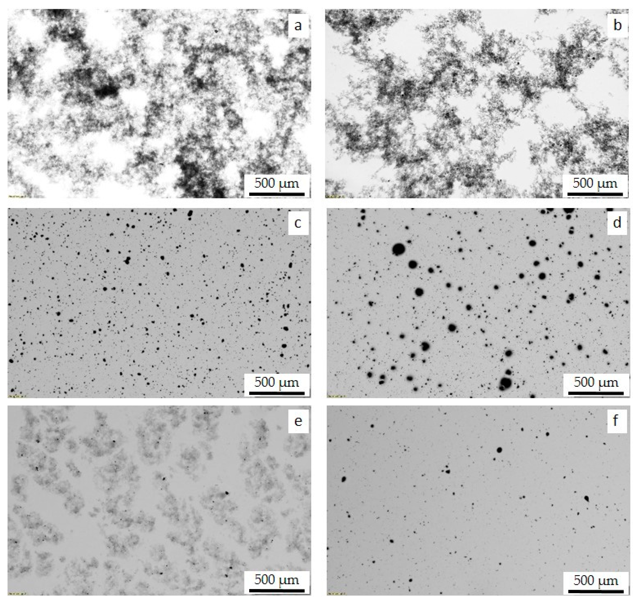
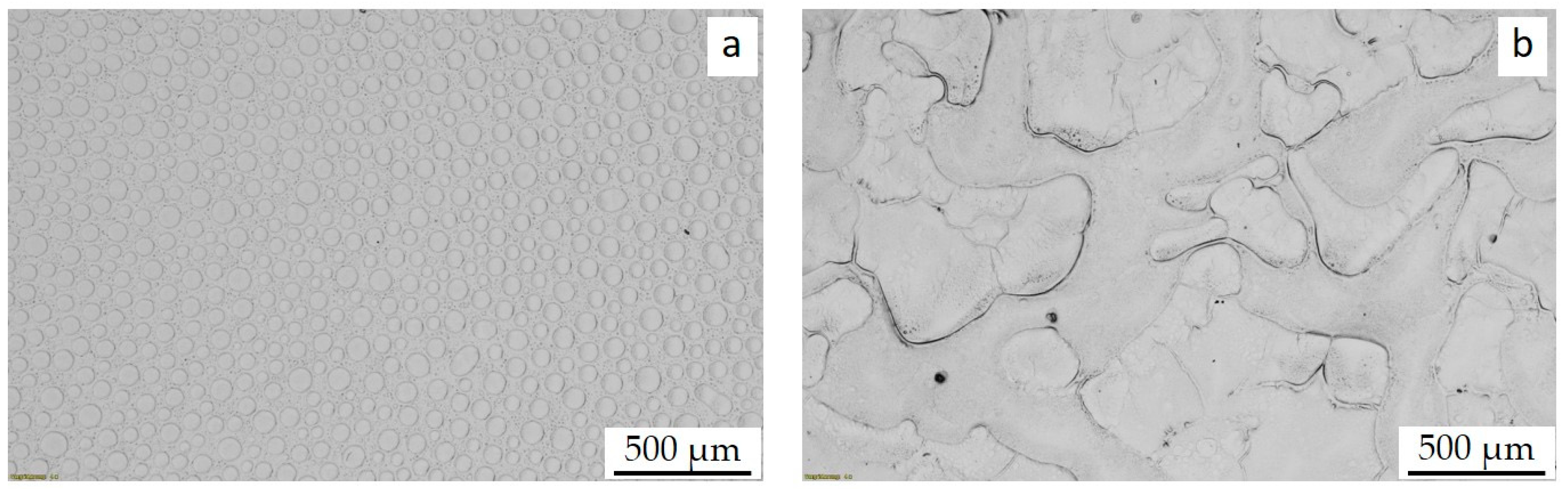
3.2. MWCNT Dispersion in PS and PB Homopolymers and in PS/PB Blends

MWCNTs of type NC 7000 from Nanocyl have been shown to disperse well in various polymer matrices and also in aqueous surfactants [33] and organic solvents [34] and were therefore selected for this study. 1 wt % of MWCNTs were first dispersed in the pure homopolymers and in macrophase-separated PS/PB blends. In Figure 2a,b TLM images of thin films prepared on glass substrates were presented, visualizing the macrodispersion of NC 7000 in PS and in PB films made from toluene. The MWCNTs form a fluffy agglomerate network in the PS and in the PB matrix, which results from the re-agglomeration of the dispersed CNTs during evaporation of the solvent [34] and indicate a poor stability of the CNT-dispersion in the polymer solution. This process is also called secondary agglomeration and was described by Alig et al. as a process that takes place in quiescent melt or under shear deformation [35]. Similar results were found in films made from chloroform (not shown here).
The functionalization of the CNTs with PS leads to a significantly changed dispersion behavior of the CNTs in PS-toluene solutions and thus to an improved film quality. As can be seen in Figure 2c, the polymer matrix appears uniformly gray, which indicates that the majority of the CNT-PS are homogeneously distributed and isolated. The films are very transparent, but exhibit many compact CNT agglomerates homogeneously distributed in the matrix with sizes of 5 to 20 µm, in some cases up to 35 µm.
The PS functionalization also enhances the dispersion of the CNTs in the PB matrix (Figure 2d), resulting in high transparency of the films. However, many large compact CNT agglomerates remain, some of which are 50 µm to 100 µm in size, which could not be separated by ultrasonic treatment.
The macrodispersion of the functionalized MWCNTs CNT-C18 in PS is represented by the TLM image in Figure 2e. In the PS matrix, part of the CNT-C18 are well dispersed and homogeneously distributed (grey background). Others form fluffy agglomerates similar to the composite films containing NC 7000 (see Figure 2a,b) indicating secondary agglomeration during the evaporation of the solvent. In contrast, CNT-C18 are very well dispersed in the PB matrix with a small fraction of compact agglomerates, which are very homogeneously distributed in the matrix (Figure 2f), that is also visible in a significantly higher transparency of the films.

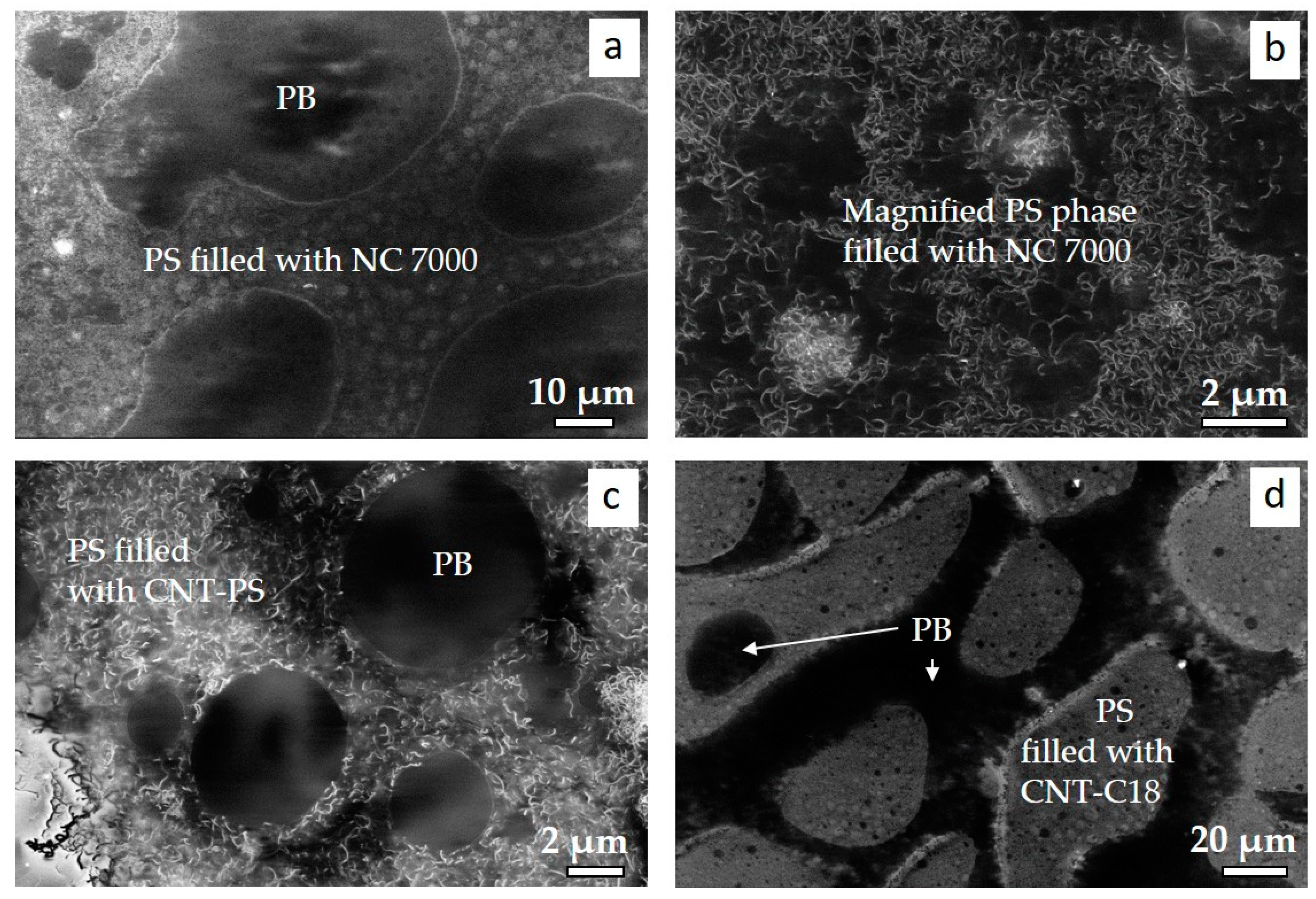
3.3. MWCNT Dispersion and Localization Behavior in PS/PB Blends

PS/PB films prepared from the solvent toluene have a strongly phase separated structure with PB domains distributed in the PS matrix (Figure 3a). In contrast, the phase miscibility of the two components is significantly increased when using the solvent chloroform. The domains are larger and a mixed phase is partially formed (Figure 3b).
The addition of MWCNTs affects the phase separation of the blend components as shown in Figure 4, Figure 5 and Figure 6, compared to the pure blend (see Figure 3). The blend morphology in samples made from toluene is more complex varying from co-continuous to disperse within a sample as indicated by the images in Figure 5a and Figure 6a. The PS/PB blend composition of 60/40 is in the range of expected phase inversion of the morphology from co-continuous to dispersed PB droplets as discussed by Joseph et al. for melt extruded PS/PB blends. Blend morphology and point of inversion were found to be strongly dependent on absolute viscosity and viscosity ratios, interfacial tension, phase dimensions and mixing conditions [36]. Therefore, the addition of a filler, ultrasonic treatment and the time dependent evaporation of the solvent significantly influences the morphology formation in the blends. In samples made from chloroform the miscibility of the two phase seems to be enhanced by the addition of functionalized CNTs (Figure 5b and Figure 6b) compared to the pristine blend and blend with non-functionalized MWCNTs NC 7000.
In blends with NC 7000 prepared from toluene, the CNTs form a cloud-like network structure (Figure 4a), caused by re-agglomeration of the CNTs during evaporation due to unstable CNT dispersion in the polymer solution. The CNTs are mainly distributed in the PS matrix, while the PB domains appear free of CNTs. In blends prepared from chloroform, the CNTs form a re-agglomerated network spanning over the whole blend structure (Figure 4b). It is difficult to distinguish between the two phases in the TLM images and to determine exactly whether the CNTs localize in one phase. Nevertheless, it is possible to identify apparently unfilled areas that can be assigned to the PB phase.
The functionalization of the MWCNTs with monoamino-terminated PS significantly changes the dispersion behavior of the CNTs in the PS/PB blends for both, composite films made from toluene as shown in Figure 5a,c and composite films made from chloroform as displayed in Figure 5b,d. CNT-PS were dispersed much more finely throughout the entire blend morphology, with a clear tendency to accumulate in the PS phase (appears darker than PB phase in the TLM images). Compact CNT-PS agglomerates are predominantly localized in the PS phase and at the phase interface. These are primary agglomerates that have not been dispersed by the ultrasound treatment. Thus, the stability of the CNT-PS dispersion in the polymer solutions withstands the entire evaporation process without secondary agglomeration.
In blend composites made from toluene containing functionalized MWCNTs CNT-C18, hardly any compact CNT agglomerates are visible (Figure 6a,c); CNT-C18 are even better dispersed in the blend than CNT-PS, with clear preference to localize in the (more or less disperse) PS phase. However, using the solvent chloroform, CNT-C18 tend to form cloudy agglomerates within the continuous PS phase (Figure 6b,d), whereas the disperse PB phase seems to be free of CNTs.
To get a closer look into the blend phases and to verify the localization behavior of the CNTs, SEM investigations of the blend composite films were conducted using an InLens detector to visualize the CNTs. SEM images of PS/PB blend composites made from toluene are illustrated in Figure 7. The CNTs appear bright in the images. Both the pure and the modified CNTs localize preferentially in the PS phase and at the PS-PB interface. The same results were found for composites made from chloroform (not shown here).

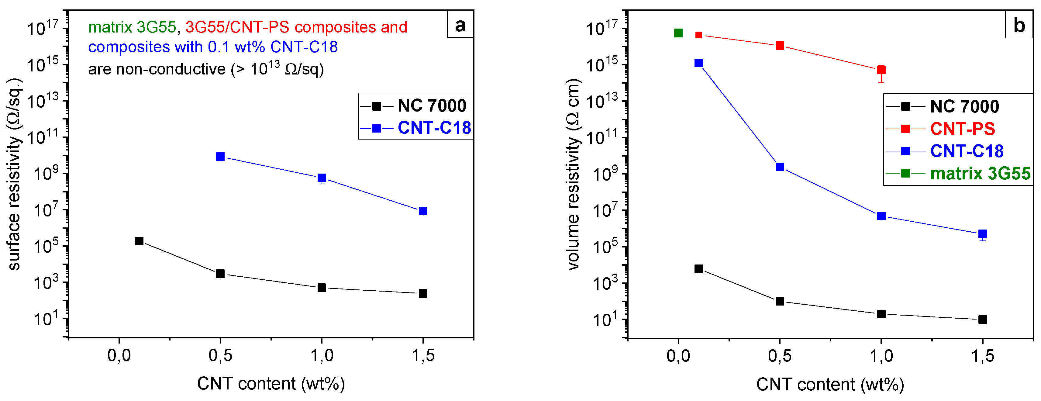
3.4. Electrical Surface Resistivity

Results of surface resistivity measurements of composite films containing 1 wt % of unmodified MWCNTs (NC7000) are presented in Table 2. Films based on PS and made from toluene exhibit the lowest resistivity values of about 2.6 × 10⁴ Ohm/sq. Interestingly, PB/NC 7000 composite films are non-conductive, despite showing similar CNT macrodispersion in the TLM images like PS/NC 7000 composites (see Figure 2a,b). This effect makes it clear that not only the CNT macrodispersion is decisive for the assessment of CNT percolation. The distribution of individual CNTs and the combination of individual CNTs and agglomerates also determine the formation of a continuous conductive CNT network in the polymer matrix.
The chemical functionalization of the CNTs with n-octadecylamine or monoamino-terminated PS has an insulating effect on the electrical conductivity of the corresponding polymer composites. On one hand, the grafted polymer chains slightly decrease the electrical conductivity of the modified CNTs (see Table 1). On the other hand, the modification increases the compatibility of the functionalized CNTs with the polymer matrix. As a result, the CNTs are better dispersed in the matrix, isolated from each other and surrounded by polymer chains. In the case of CNT-PS, π–π interactions between the phenyl rings of the monoamino-terminated PS and the PS chains in the matrix are assumed for the increased compatibility [37].

3.5. CNT Dispersion in BCP/MWCNT Composites

Films of BCP/MWCNT composites were prepared using the solvent toluene. Light microscopy images captured in transmission mode of composites containing 1 wt % of MWCNTs evaporated on glass substrates are shown in Figure 8. Photographs of the films are presented in the inserted images of Figure 8. The thickness of the films is about 30 µm. Similar to the CNT dispersion in homopolymers and blends the unmodified NC 7000 form a cloudy-like network structure in the 3G55 starblock copolymer caused by secondary agglomeration during evaporation (Figure 8a). In contrast, the CNT dispersion is strongly improved by the addition of modified CNTs (Figure 8b,c), whereby CNT-PS exhibit compact primary agglomerates that are homogeneously distributed in the matrix (Figure 8b). Nevertheless, the film is very transparent and the larger agglomerates are visible as black dots. Composite films with CNT-C18 are almost free of agglomerates and exhibit very good transparency (Figure 8c).
Further investigations on morphology and electrical and mechanical properties were conducted on freestanding films with a thickness of ~0.3 mm containing MWCNT amounts between 0.1 and 1.5 wt %. Due to the higher thickness of these films, they are no longer transparent already with CNT contents of 0.5 wt %. The CNT macrodispersion can be discussed comparing composite films with 0.1 wt % MWCNTs. Films with unmodified NC 7000 exhibit very inhomogeneous CNT dispersion, with highly transparent areas and regions of cloudy-like CNT agglomerate formation, caused by secondary agglomeration during the evaporation process due to unstable CNT dispersion in the polymer-solution (Figure 9a). Functionalization of the MWCNTs with monoamino-terminated PS increases the polymer-CNT interaction and thus the compatibility between filler and matrix leading to high stability of the CNT dispersion. Therefore, no re-agglomeration process takes place during the evaporation of the solvent. The resulting films are grey-colored (Figure 9b, middle sample) compared to the highly transparent 3G55 matrix (Figure 9b, left sample), but still exhibit good transparency, reflecting the high dispersability of the CNT-PS. This correlates with the results for PS/PB blends (see Figure 5).
Interestingly, BCP composite films containing functionalized CNT-C18 exhibit a fluffy agglomerated CNT structure similar to films containing NC 7000, but more homogeneously distributed over the entire film (Figure 9c). This is in contrast to the high film quality of BCP/CNT-C18 composites prepared on glass substrates (see Figure 8c). As described in the experimental part, the duration of the evaporation process was about three days. For film production on glass substrates, significantly smaller amounts of the solutions were used, which evaporated completely within about 30–60 min. This means that in the former case there is considerably more time for the CNTs to re-agglomerate. This process occurred because the dispersion of the functionalized CNT-C18 was not stable over several days.

3.6. BCP Morphology and Nanocomposite Structure

As discussed in detail in other studies [23,38,39], the star block copolymer has a complex morphology. Using small-angle X-ray scattering (SAXS) and TEM, Thomann et al. described the BCP morphology as a lamellar structure exhibiting tube-like PB-rich phases which envelope the PS-rich phase and are connected by lamellae in between [40]. Adhikari et al. described the structure as interpenetrating co-continuous morphology where the PS outer blocks partially mix with the random PS-co-PB core of the starblock copolymer [38]. In one of our previous studies, TEM investigations revealed a rather worm-like structure with a mix of short and long lamellae for melt-extruded samples [9]. As is well known, morphology formation can be significantly influenced by the type of processing and, in the case of solution casting, by the choice of casting solvent [41] or by the introduction of (phase-) selective solvents [42]. In the present study, TEM investigations of the free-standing solvent cast films made from toluene revealed a mixed structure with short lamellae and PS cylinders as shown in Figure 10a. The PB phase was stained and appears dark. The addition of MWCNTs does not affect the BCP morphology, a fact that has already been observed in melt-mixed BCP/MWCNT composites [9,10]. Figure 10b shows an example of the morphology of a BCP composite with 0.5 wt % CNT-PS. In comparison, Figure 10c shows a CNT agglomerate and individual CNTs in a non-contrasted sample in which the BCP structure is not visible. It cannot be clearly demonstrated whether the CNT-PS preferentially localize in the PS-rich phase, as was observed in PS/PB blends. The TEM images in Figure 10 show that the MWCNTs are predominantly too long to accumulate in one of the BCP phases. However, well isolated shorter MWCNTs may be localized in the PS phase, which is not visible in the TEM. This assumption is supported by the fact that composites with CNT-PS in the investigated range of 0.1 to 1 wt % MWCNTs are not electrically conductive (Figure 11, next section), i.e., do not form a percolated network extending over the entire matrix. Possibly they accumulate preferentially in the non-continuous PS-rich phase and cannot form a percolated network extending across the entire matrix due to the PB-rich phase enveloping the PS domains. In addition, PS-functionalization can exert an insulating effect on the CNTs, although powder conductivity results have shown that the electrical conductivity of CNT-PS is only slightly reduced by functionalization.

3.7. Electrical Properties of BCP/MWCNT Composites

Surface resistivity and volume resistivity of the BCP/MWCNT composites as a function of CNT content are displayed in Figure 11a,b, respectively. Composites containing NC 7000 are electrically conductive already at a very-low MWCNT content of 0.1 wt %, exhibiting surface and volume resistivity values of 2 × 10⁵ Ω/sq. and 6 × 10⁴ Ω∙cm, respectively. With increase of the MWCNT content up to 1.5 wt % the resistivity values further decrease to 240 Ω/sq. and 10 Ω∙cm, respectively. Similar to the results of the investigated PS/PB blends, BCP composites containing functionalized CNT-PS are non-conductive in the investigated range of CNT contents up to 1 wt %. In contrast, BCP composites containing functionalized CNT-C18 exhibit a percolation threshold approximately at a CNT content of 0.5 wt %, which is expressed in a significant drop in resistivity in this range. However, with further increase of the CNT content up to 1.5 wt % the resistivity maintains at a rather higher level, exhibiting values of 8 × 10⁶ Ω/sq. and 5 × 10⁵ Ω∙cm for surface and volume resistivity, respectively. The results of the resistivity measurements correlate very well with the observed CNT dispersion in the films examined. As already discussed in the literature [9,35], very good CNT dispersion tends to hinder the formation of a conductive CNT network within the matrix and requires higher filler contents. In contrast, a mixture of very-well-dispersed CNTs and agglomerated CNTs promotes percolation of the CNTs and leads to high electrical conductivity.

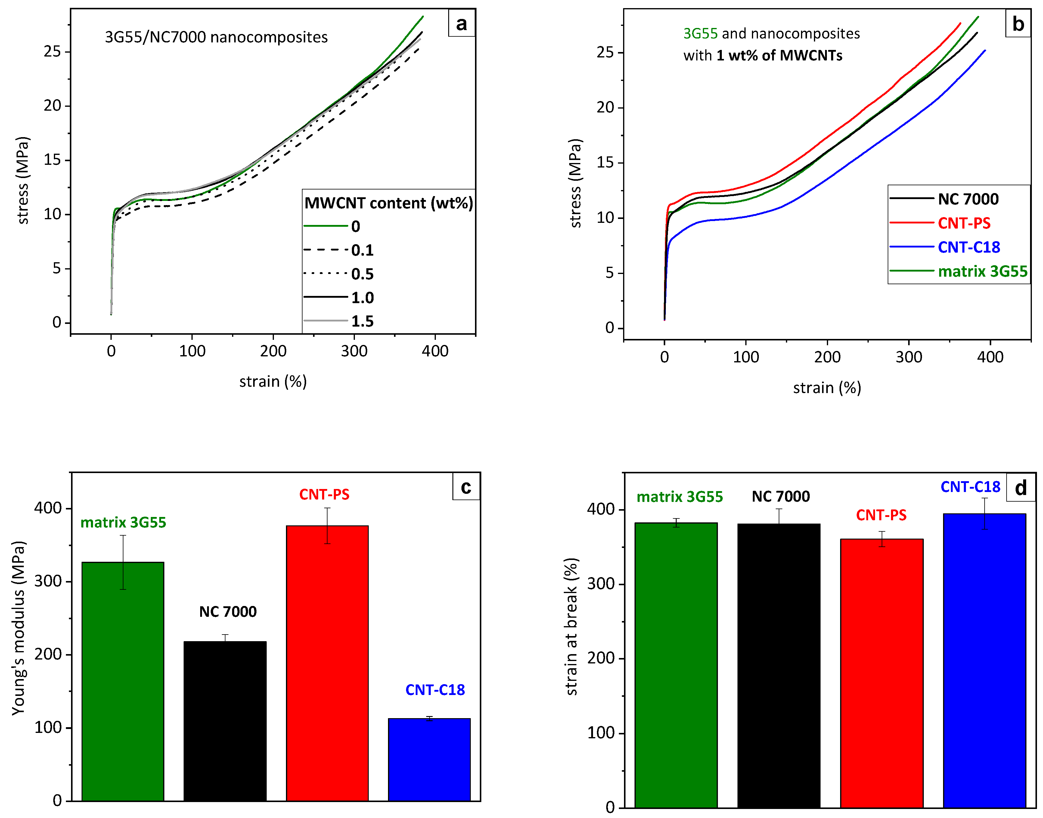
3.8. Stress–Strain Behavior of BCP/MWCNT Composites

The stress–strain diagrams of the BCP composites containing unmodified NC 7000 are presented in Figure 12a. The mechanical behavior of the 3G55 matrix (green curve) is characterized by a combination of good strength and high elongation, which is typical for such styrene-butadiene block copolymers and has already been discussed in detail in the literature [9,43]. Note the formation of two yield points for this star block copolymer. Such a ‘double yielding’ effect is related to morphology-based micromechanical deformation mechanisms and was first described by Adhikari et al. [38]. The addition of NC 7000 up to 1.5 wt % does not have a significant influence on the stress–strain behavior of the BCP. The elastomeric property profile of the BCP is maintained, exhibiting high ductility and large strain at break values of ~380%. Due to the inhomogeneous CNT dispersion and presence of big agglomerates the filler does not contribute to reinforcement of the BCP but lead to a decrease of the stiffness of the BCP as represented by the decreased Young’s modulus of the BCP/NC 7000 composite containing 1 wt % of MWCNTs in Figure 12c. For all investigated composites containing 0.1–1.5 wt % of NC 7000 the Young’s modulus remains at the same level. In contrast to the 3G55 matrix, the stress–strain curves do not show a distinct first yield point.
In Figure 12b, stress–strain diagrams of BCP composites with 1 wt % of unmodified and functionalized MWCNTs and of the BCP matrix are compared. Figure 12c,d show the corresponding values for the Young’s modulus and the strain at break. The functionalization of the MWCNTs with monoamino-terminated PS leads to a slight reinforcement effect in the BCP/CNT-PS composite, which is reflected by higher yield points (red curve in Figure 12b) and a small increase of the Young’s modulus (Figure 12c) combined with a slight decrease in elongation (Figure 12d). It should be noted that the addition of 0.1 and 0.5 wt % CNT-PS to the BCP matrix initially leads to a gradual reduction in stiffness to a value of 270 MPa (not shown here) until it increases again significantly to 380 MPa for composites with 1 wt % CNT-PS, which is slightly above the value of the BCP matrix. However, if one takes into account the high standard deviation of Young’s modulus values of the BCP matrix (Figure 12c), it is difficult to interpret these fluctuations on the basis of the CNT addition.
Composites with n-octadecylamine functionalized CNT-C18 (blue curve in Figure 12b) exhibit a different deformation behavior with significantly reduced Young’s modulus, no distinct first yield point and slightly reduced tensile strength, while maintaining large strain at break. This effect cannot be explained by the addition of a reinforcing filler such as CNTs and suggests that, unlike composites with CNT-PS, there is a morphological change caused by the functional C18 groups of the modified MWCNTs. Further studies will focus on a better understanding of these structure-property relations using further methods for structure elucidation and characterization of the phase behavior, such as high-resolution TEM, SAXS, and dynamic mechanical analysis.
It can be concluded from these results that the interaction between the BCP matrix and the unmodified MWCNTs NC 7000 is rather low and does not contribute to reinforce the BCP. However, while maintaining the matrix-specific mechanical properties, the additional functionality of electrical conductivity can be introduced with the addition of only 0.1 wt % NC 7000. If CNT-PS is mixed into the BCP matrix, a significant improvement of the CNT dispersion can be observed compared to the unmodified MWCNTs, which is reflected in a good film transparency. Whether a localization of the CNT-PS in the PS phase occurs could not be clearly demonstrated. However, such composites with contents of up to 1 Ma% are not electrically conductive. Apart from a small strengthening effect, no significant improvement in the mechanical properties of composites containing 1 Ma% CNT-PS were observed. For BCP composites containing CNT-C18, the film quality is dependent on the processing conditions due to limited dispersion stability of the CNTs. The stiffness of these composites is significantly reduced compared to the BCP matrix. The electrical percolation threshold occurs at a MWCNT content of about 0.5 wt %, and up to a MWCNT content of 1.5 wt % the resistivity remains at a rather high level.

4. Conclusions

In order to obtain a better understanding of possible dispersion and localization mechanisms of CNTs in styrene-butadiene based block copolymers and to be able to use them specifically for the development of new functional materials with specific electrical properties, the dispersion behavior of unmodified and functionalized MWCNTs in the corresponding homopolymers PS and PB, as well as in their physical immiscible blend, was investigated. In the homopolymers, as well as in the blend, the CNT dispersion was significantly improved by functionalizing the CNTs with monoamino-terminated PS or n-octadecylamine. The dispersion stability of CNT-PS is significantly higher than that of CNT-C18. All MWCNT types preferable localize in the PS phase of the blend. Only composites with unmodified MWCNTs were electrically conductive as the presence of CNT agglomerates promotes the formation of an electrically conductive CNT network rather than well-dispersed CNTs. In the BCP matrix, similar effects were observed for the CNT dispersion mechanism. The functionalization of the MWCNTs improves the dispersability and dispersion stability of the CNTs in the BCP matrix. The electrical conductivity is eliminated (CNT-PS) or significantly reduced (CNT-C18) compared to BCP composites with unmodified MWCNTs, which are electrically conductive already at a filler content of 0.1 wt %. The mechanical investigations revealed an influence of the CNT functionalization on the stiffness of BCP composites. While 1 wt % CNT-PS cause a slight increase in yield stress and Young’s modulus, all composites with CNT-C18 exhibit a significant reduction of those parameters compared to the BCP matrix. A localization of the CNTs in one of the block copolymer phases could not be detected. From the results of PS/PB blends it is assumed that the CNTs interact preferentially with the PS phase and accumulate there. This effect is particularly expected with CNT-PS, since π–π interactions between the phenyl rings of the monoamino-terminated PS and the PS chains in the BCP matrix may increase compatibility. CNT-C18 may cause a small change in the morphology of the BCP, which needs further investigation.
Another important aspect that should not be neglected is the unfavorable geometric proportions between the nm-sized block copolymer domains and the µm-long CNTs, which is rather an obstacle for a complete embedding of the CNTs in the BCP phases. The use of significantly shorter CNTs and the expansion of the block copolymer domains is therefore also the subject of further investigations.

Author Contributions

Conceptualization, U.S.; Methodology, U.S. and L.J.; Validation, U.S., L.J., and L.H.; Investigation, U.S., L.H. and L.J.; Data curation, U.S.; Writing—original draft preparation, U.S. and L.J.; Writing—review and editing, U.S., L.J., and L.H.; Visualization, U.S. and L.H.; Supervision, U.S.; Project administration, U.S.; Funding acquisition, U.S. All authors have read and agreed to the published version of the manuscript.

Funding

This research was funded by the Deutsche Forschungsgemeinschaft (German Research Foundation), grant number STA 1392/1-1.

Acknowledgments

The authors thank the students Felix Buchta, Alik Pahlow, and Maliheh Davoodabadi and the technician Ulrike Jentzsch-Hutschenreuther from the Leibniz Institute of Polymer Research Dresden (IPF) for their help in sample preparation, light microscopy, and conductivity measurements. We also thank Karsten Scheibe and Holger Scheibner from the mechanical department of IPF for conducting tensile tests. We further thank Manuela Heber from IPF for her help in SEM analysis. We also acknowledge Uta Reuter from IPF for her help with the TEM studies.

Conflicts of Interest

The authors declare no conflict of interest.

References

  1. Khandpur, A.K.; Förster, S.; Bates, F.S.; Hamley, I.W.; Ryan, A.; Bras, W.; Almdal, K.; Mortensen, K. Polyisoprene-Polystyrene Diblock Copolymer Phase Diagram near the Order-Disorder Transition. Macromolecules 1995, 28, 8796–8806. [Google Scholar] [CrossRef]
  2. Bockstaller, M.R.; Mickiewicz, R.A.; Thomas, E.L. Block Copolymer Nanocomposites: Perspectives for Tailored Functional Materials. Adv. Mater. 2005, 17, 1331–1349. [Google Scholar] [CrossRef]
  3. Lu, L.; Zhou, Z.; Zhang, Y.; Wang, S.; Zhang, Y. Reinforcement of styrene–butadiene–styrene tri-block copolymer by multi-walled carbon nanotubes via melt mixing. Carbon 2007, 45, 2621–2627. [Google Scholar] [CrossRef]
  4. Pedroni, L.G.; Soto-Oviedo, M.A.; Rosolen, J.M.; Felisberti, M.I.; Nogueira, A.F. Conductivity and mechanical properties of composites based on MWCNTs and styrene-butadiene-styrene block™ copolymers. J. Appl. Polym. Sci. 2009, 112, 3241–3248. [Google Scholar] [CrossRef]
  5. Meier, J.G.; Crespo, C.; Pelegay, J.; Castell, P.; Sainz, R.; Maser, W.; Benito, A. Processing dependency of percolation threshold of MWCNTs in a thermoplastic elastomeric block copolymer. Polymer 2011, 52, 1788–1796. [Google Scholar] [CrossRef]
  6. Pedroni, L.; Araujo, J.; Felisberti, M.I.; Nogueira, A. Nanocomposites based on MWCNT and styrene–butadiene–styrene block copolymers: Effect of the preparation method on dispersion and polymer–filler interactions. Compos. Sci. Technol. 2012, 72, 1487–1492. [Google Scholar] [CrossRef]
  7. Périé, T.; Brosse, A.-C.; Tencé-Girault, S.; Leibler, L. Mechanical and electrical properties of multi walled carbon nanotube/ABC block terpolymer composites. Carbon 2012, 50, 2918–2928. [Google Scholar] [CrossRef]
  8. Costa, P.; Silva, J.; Ansón-Casaos, A.; Martínez, M.T.; Abad, M.-J.; Viana, J.C.; Lanceros-Mendez, S. Effect of carbon nanotube type and functionalization on the electrical, thermal, mechanical and electromechanical properties of carbon nanotube/styrene–butadiene–styrene composites for large strain sensor applications. Compos. Part B Eng. 2014, 61, 136–146. [Google Scholar] [CrossRef] [Green Version]
  9. Staudinger, U.; Satapathy, B.K. Influence of Carbon Nanotubes on the Morphology and Properties of Styrene-Butadiene Based Block Copolymers. Macromol. Symp. 2017, 373, 1700030. [Google Scholar] [CrossRef]
  10. Staudinger, U.; Satapathy, B.K.; Jehnichen, D. Nanofiller Dispersion, Morphology, Mechanical Behavior, and Electrical Properties of Nanostructured Styrene-Butadiene-Based Triblock Copolymer/CNT Composites. Polymer 2019, 11, 1831. [Google Scholar] [CrossRef] [Green Version]
  11. Park, I.; Lee, W.; Kim, J.; Park, M.; Lee, H. Selective sequestering of multi-walled carbon nanotubes in self-assembled block copolymer. Sens. Actuators B Chem. 2007, 126, 301–305. [Google Scholar] [CrossRef]
  12. Peponi, L.; Tercjak, A.; Gutierrez, J.; Cardinali, M.; Mondragon, I.; Valentini, L.; Kenny, J.M. Mapping of carbon nanotubes in the polystyrene domains of a polystyrene-b-polyisoprene-b-polystyrene block copolymer matrix using electrostatic force microscopy. Carbon 2010, 48, 2590–2595. [Google Scholar] [CrossRef]
  13. Liu, Y.-T.; Zhang, Z.-L.; Zhao, W.; Xie, X.-M.; Ye, X. Selective self-assembly of surface-functionalized carbon nanotubes in block copolymer template. Carbon 2009, 47, 1883–1885. [Google Scholar] [CrossRef]
  14. Wode, F.; Tzounis, L.; Kirsten, M.; Constantinou, M.; Georgopanos, P.; Rangou, S.; Zafeiropoulos, N.; Avgeropoulos, A.; Stamm, M. Selective localization of multi-wall carbon nanotubes in homopolymer blends and a diblock copolymer. Rheological orientation studies of the final nanocomposites. Polymer 2012, 53, 4438–4447. [Google Scholar] [CrossRef]
  15. Albuerne, J.; Fierro, A.B.-D.; Abetz, C.; Fierro, D.; Abetz, V. Block Copolymer Nanocomposites Based on Multiwall Carbon Nanotubes: Effect of the Functionalization of Multiwall Carbon Nanotubes on the Morphology of the Block Copolymer. Adv. Eng. Mater. 2011, 13, 803–810. [Google Scholar] [CrossRef]
  16. Hasanabadi, N.; Nazockdast, H.; Gajewska, B.; Balog, S.; Gunkel, I.; Bruns, N.; Lattuada, M. Structural Behavior of Cylindrical Polystyrene-block-Poly(ethylene-butylene)-block-Polystyrene (SEBS) Triblock Copolymer Containing MWCNTs: On the Influence of Nanoparticle Surface Modification. Macromol. Chem. Phys. 2017, 218, 1700231. [Google Scholar] [CrossRef] [Green Version]
  17. Garate, H.; Fascio, M.L.; Mondragon, I.; D’Accorso, N.B.; Goyanes, S. Surfactant-aided dispersion of polystyrene-functionalized carbon nanotubes in a nanostructured poly(styrene-b-isoprene-b-styrene) block copolymer. Polymer 2011, 52, 2214–2220. [Google Scholar] [CrossRef]
  18. Meincke, O.; Kaempfer, D.; Weickmann, H.; Friedrich, C.; Vathauer, M.; Warth, H. Mechanical properties and electrical conductivity of carbon-nanotube filled polyamide-6 and its blends with acrylonitrile/butadiene/styrene. Polymer 2004, 45, 739–748. [Google Scholar] [CrossRef]
  19. Göldel, A.; Kasaliwal, G.; Pötschke, P. Selective Localization and Migration of Multiwalled Carbon Nanotubes in Blends of Polycarbonate and Poly(styrene-acrylonitrile). Macromol. Rapid Commun. 2009, 30, 423–429. [Google Scholar] [CrossRef]
  20. Bose, S.; Bhattacharyya, A.R.; Khare, R.A.; Kulkarni, A.R.; Patro, T.U.; Sivaraman, P. Tuning the dispersion of multiwall carbon nanotubes in co-continuous polymer blends: A generic approach. Nanotechnology 2008, 19, 335704. [Google Scholar] [CrossRef]
  21. Bose, S.; Bhattacharyya, A.R.; Kulkarni, A.R.; Pötschke, P. Electrical, rheological and morphological studies in co-continuous blends of polyamide 6 and acrylonitrile–butadiene–styrene with multiwall carbon nanotubes prepared by melt blending. Compos. Sci. Technol. 2009, 69, 365–372. [Google Scholar] [CrossRef]
  22. Gültner, M.; Göldel, A.; Pötschke, P. Tuning the localization of functionalized MWCNTs in SAN/PC blends by a reactive component. Compos. Sci. Technol. 2011, 72, 41–48. [Google Scholar] [CrossRef]
  23. Knoll, K.; Nießner, N. Styrolux+ and Styroflex+-From Transparent High Impact Polystyrene to New Thermoplastic Elastomers: Syntheses, Applications and Blends with other Styrene based Polymers. Macromol. Symp. 1998, 132, 231–243. [Google Scholar] [CrossRef]
  24. Saalwächter, K.; Thomann, Y.; Hasenhindl, A.; Schneider, H. Direct Observation of Interphase Composition in Block Copolymers. Macromolecules 2008, 41, 9187–9191. [Google Scholar] [CrossRef] [Green Version]
  25. NANOCYL® NC7000TM Technical Data Sheet, 12th July 2016, V08. Available online: https:www.nanocyl.com (accessed on 30 March 2020).
  26. Postma, A.; Davis, T.P.; Evans, R.; Li, G.; Moad, G.; O’Shea, M.S. Synthesis of Well-Defined Polystyrene with Primary Amine End Groups through the Use of Phthalimido-Functional RAFT Agents. Macromolecules 2006, 39, 5293–5306. [Google Scholar] [CrossRef]
  27. Krause, B.; Boldt, R.; Häußler, L.; Pötschke, P. Ultralow percolation threshold in polyamide 6.6/MWCNT composites. Compos. Sci. Technol. 2015, 114, 119–125. [Google Scholar] [CrossRef]
  28. Price, G.; Smith, P.F. Ultrasonic degradation of polymer solutions. 1. Polystyrene revisited. Polym. Int. 1991, 24, 159–164. [Google Scholar] [CrossRef]
  29. Price, G.; Smith, P.F. Ultrasonic degradation of polymer solutions: 2. The effect of temperature, ultrasound intensity and dissolved gases on polystyrene in toluene. Polymer 1993, 34, 4111–4117. [Google Scholar] [CrossRef]
  30. Chubarova, E.V.; Melenevskaya, E.Y.; Shamanin, V.V. Chain Degradation under Low-Intensity Sonication of Polymer Solutions in the Presence of Filler: Mechanism of Ultrasonic Degradation of Flexible Chain Macromolecules. J. Macromol. Sci. Part B 2012, 52, 873–896. [Google Scholar] [CrossRef]
  31. Ameli, A.; Arjmand, M.; Pötschke, P.; Krause, B.; Sundararaj, U. Effects of synthesis catalyst and temperature on broadband dielectric properties of nitrogen-doped carbon nanotube/polyvinylidene fluoride nanocomposites. Carbon 2016, 106, 260–278. [Google Scholar] [CrossRef]
  32. Arjmand, M.; Chizari, K.; Krause, B.; Pötschke, P.; Sundararaj, U. Effect of synthesis catalyst on structure of nitrogen-doped carbon nanotubes and electrical conductivity and electromagnetic interference shielding of their polymeric nanocomposites. Carbon 2016, 98, 358–372. [Google Scholar] [CrossRef]
  33. Krause, B.; Mende, M.; Pötschke, P.; Petzold, G. Dispersability and particle size distribution of CNTs in an aqueous surfactant dispersion as a function of ultrasonic treatment time. Carbon 2010, 48, 2746–2754. [Google Scholar] [CrossRef]
  34. Staudinger, U.; Krause, B.; Steinbach, C.; Pötschke, P.; Voit, B. Dispersability of multiwalled carbon nanotubes in polycarbonate-chloroform solutions. Polymer 2014, 55, 6335–6344. [Google Scholar] [CrossRef]
  35. Alig, I.; Pötschke, P.; Lellinger, D.; Skipa, T.; Pegel, S.; Kasaliwal, G.R.; Villmow, T. Establishment, morphology and properties of carbon nanotube networks in polymer melts. Polymer 2012, 53, 4–28. [Google Scholar] [CrossRef]
  36. Joseph, S.; Rutkowska, M.; Jastrzębska, M.; Janik, H.; Haponiuk, J.T.; Thomas, S. Polystyrene/polybutadiene blends: An analysis of the phase-inversion region and cophase continuity and a comparison with theoretical predictions. J. Appl. Polym. Sci. 2003, 89, 3700. [Google Scholar] [CrossRef]
  37. Martins, J.A.; Cruz, V.S.; Paiva, M.C. Flow Activation Volume in Composites of Polystyrene and Multiwall Carbon Nanotubes with and without Functionalization. Macromolecules 2011, 44, 9804–9813. [Google Scholar] [CrossRef]
  38. Adhikari, R.; Buschnakowski, M.; Henning, S.; Goerlitz, S.; Huy, T.A.; Lebek, W.; Godehardt, R.; Michler, G.H.; Lach, R.; Geiger, K.; et al. Double Yielding in a Styrene/Butadiene Star Block Copolymer. Macromol. Rapid Commun. 2004, 25, 653–658. [Google Scholar] [CrossRef]
  39. Satapathy, B.; Lach, R.; Weidisch, R.; Schneider, K.; Janke, A.; Knoll, K. Morphology and crack toughness behaviour of nanostructured block copolymer/homopolymer blends. Eng. Fract. Mech. 2006, 73, 2399–2412. [Google Scholar] [CrossRef]
  40. Thomann, Y.; Thomann, R.; Hasenhindl, A.; Mülhaupt, R.; Heck, B.; Knoll, K.; Steininger, H.; Saalwächter, K. Gradient Interfaces in SBS and SBS/PS Blends and Their Influence on Morphology Development and Material Properties. Macromolecules 2009, 42, 5684–5699. [Google Scholar] [CrossRef]
  41. Sakurai, S.; Sakamoto, J.; Shibayama, M.; Nomura, S. Effects of microdomain structures on the molecular orientation of poly(styrene-block-butadiene-block-styrene) triblock copolymer. Macromolecules 1993, 26, 3351–3356. [Google Scholar] [CrossRef]
  42. Alexandridis, P.; Spontak, R.J. Solvent-regulated ordering in block copolymers. Curr. Opin. Colloid Interface Sci. 1999, 4, 130–139. [Google Scholar] [CrossRef]
  43. Adhikari, R.; Huy, T.A.; Buschnakowski, M.; Michler, G.H.; Knoll, K. Asymmetric PS-block-(PS-co-PB)-block-PS block copolymers: Morphology formation and deformation behaviour. New J. Phys. 2004, 6, 28. [Google Scholar] [CrossRef]
Figure 1. Thermogravimetric analysis (TGA)-curves of MWCNTs NC 7000, CNT-C18, and CNT-PS.
Jcs 04 00040 g001
Figure 2. TLM images of PS and PB homopolymers with 1 wt % of MWCNTs dispersed in toluene and prepared on glass substrates: (a) PS/NC 7000, (b) PB/NC 7000, (c) PS/CNT-PS, (d) PB/CNT-PS, (e) PS/CNT-C18, and (f) PB/CNT-C18.
Jcs 04 00040 g002
Figure 3. TLM images of PS/PB blends made from (a) toluene and (b) chloroform, prepared on glass substrates.
Jcs 04 00040 g003
Figure 4. TLM images of PS/PB blends with 1wt % of NC 7000 dispersed in (a) toluene and (b) chloroform, prepared on glass substrates.
Jcs 04 00040 g004
Figure 5. TLM images of PS/PB blends with 1 wt % of CNT-PS dispersed in toluene (a,c) and chloroform (b,d) prepared on glass substrates; (c,d) at higher magnification.
Jcs 04 00040 g005
Figure 6. TLM images of PS/PB blends with 1 wt % of CNT-C18 dispersed in toluene (a,c) and chloroform (b,d) prepared on glass substrates; (c,d) at higher magnification.
Jcs 04 00040 g006
Figure 7. SEM images of PS/PB blends with 1 wt % of MWCNTs dispersed in toluene, prepared on glass substrates: (a,b) NC 7000, (c) CNT-PS, and (d) CNT-C18; prepared on glass substrates; using InLens detector to visualize CNTs localized in the PS phase.
Jcs 04 00040 g007
Figure 8. TLM images and inserted photographs of BCP composite films with 1wt % of MWCNTs in toluene prepared on glass substrates: (a) NC 7000, (b) CNT-PS, (c) CNT-C18.
Jcs 04 00040 g008
Figure 9. Photographs of BCP/MWCNT composite films: (a) 0.1 wt % NC 7000, (b) matrix 3G55, 0.1 wt % CNT-PS and 1 wt % CNT-PS (from left to right), (c) 0.1 wt % CNT-C18.
Jcs 04 00040 g009
Figure 10. Nanostructured morphology analyzed via TEM of (a) 3G55 matrix and (b) BCP composite with 0.5 wt % CNT-PS; (c) Visualization of MWCNTs in a non-contrasted sample of the BCP/CNT-PS composite.
Jcs 04 00040 g010
Figure 11. (a) Surface resistivity and (b) volume resistivity of BCP/MWCNT composites as a function of CNT content.
Jcs 04 00040 g011
Figure 12. Mechanical properties of BCP/MWCNT composites: (a) stress–strain diagrams of 3G55/NC7000 composites, (b) stress–strain diagrams, (c) Young’s modulus and (d) strain at break of 3G55 and nanocomposites with 1 wt % of MWCNTs.
Jcs 04 00040 g012
Table 1. Powder conductivity of NC 7000 and functionalized CNTs at 30 MPa.
CNT SamplePowder Conductivity (S/cm)
at 30 MPa
Standard Deviation (S/cm)Powder Density
(g/cm³)
NC 700017.50.30.90
CNT-C186.50.20.72
CNT-PS1.30.10.67
Table 2. Surface resistivity of polymer/NC 7000 composite films.
Polymer MatrixSurface Resistivity (Ohm/sq.)
Solvent TolueneSolvent Chloroform
PS2.6 × 104 ± 1.7 × 1048.5 × 106 ± 3.1 × 10⁷
PBnon-conductive
(out of measuring range)
9.8 × 10¹¹ ± 1.8 × 10¹²
PS/PB (60/40)2 × 106 ± 6.2 × 1063 × 106 ± 8.3 × 10⁶

