Article

Fiber-Reinforced Composite Sandwich Structures by Co-Curing with Additive Manufactured Epoxy Lattices

1
Polymer Engineering Center, University of Wisconsin-Madison, 1513 University Ave, Madison, WI 53706, USA
2
Lineberger Comprehensive Cancer Center, University of North Carolina at Chapel Hill, Chapel Hill, NC 27599, USA
*
Author to whom correspondence should be addressed.
J. Compos. Sci. 2019, 3(2), 53; https://doi.org/10.3390/jcs3020053
Submission received: 31 March 2019 / Revised: 5 May 2019 / Accepted: 13 May 2019 / Published: 16 May 2019
(This article belongs to the Special Issue Additive Manufacturing of Polymeric and Ceramic Composites)

Abstract

:
In this paper, a new process of joining additive manufactured (AM) lattice structures and carbon fiber-reinforced plastics (CFRPs) to manufacture hybrid lattice sandwich structures without secondary bonding is investigated. Multiple variations of lattice structures are designed and 3D printed using Digital Light Synthesis (DLS) and a two-stage (B-stage) epoxy resin system. The resulting lattice structures are only partially cured and subsequently thermally co-cured with pre-impregnated carbon fiber reinforcement. The mechanical properties of the additive manufactured lattice structures are characterized by compressive tests. Furthermore, the mechanical properties of hybrid lattice sandwich structures are assessed by flexural beam testing. From compressive testing of the additive manufactured lattice structures, high specific strength can be ascertained. The mechanical behavior shows these lattice structures to be suitable for use as sandwich core materials. Flexural beam testing of hybrid lattice sandwich structures shows high strength and stiffness. Furthermore, the strength of the co-cured bond interface is high enough to surpass the strength of the lattice core.

1. Introduction

An enduring challenge in modern mechanical engineering is the design of lightweight components which are strong and highly integrated, meaning they fulfill several tasks. While currently most prevalent within the aerospace industry, more fields are now demanding materials and processes capable of fulfilling these requirements [1]. Particularly within the automotive industry, lightweight design is a key technology to meet stricter emission regulations, and to balance the shortcomings of today’s alternative drive systems [2,3].
One common approach to these challenges is the use of composite sandwich structures. Such structures are made up of a low-density core and facesheets manufactured from high specific strength fiber-reinforced polymers (FRP). Foam cores, honeycombs, or folded cores are the most commonly used [4]. The elements of sandwich structures fulfill specific roles in typical bending applications. The facesheets can be subjected to either compression or tension loads, depending on which surface of the load they are located [5]. The core fulfills two primary roles. One, it spaces out the facesheets, thus increasing the second moment of area, which leads to increasing rigidity [6]. Due to the low density of the core material, this is accompanied by only a slight increase in mass. The core’s second role is to carry the shear loads occurring under bending [6].
Overall, sandwich structures combine light weight and high mechanical properties. However, the design freedom of sandwich structures is limited, and manufacturing can be cumbersome. Furthermore, the integration of additional features, as well as the joining and assembly of sandwich structures, are significant constraints in traditional methods [6,7].
Emerging additive manufacturing (AM) technology allows for a potential solution, with nearly unrestricted design freedom and customization [8,9]. As such, geometries which were formerly impossible to manufacture are now moving into the focus of research [10,11]. One example of a geometrically complex design are lattice structures. These combine highly customizable geometry and low overall weight [12,13,14]. Thus, the utilization of additive manufactured lattice structures as core materials for sandwich structures can serve as an alternative for more traditional lightweight design strategies [10,15,16,17].
Lattice structures are an arrayed network of struts, which are connected at nodal points, and are made up of basic geometrical structures. These so-called “unit cells” are periodically or stochastically repeated in the desired directions of space. Frequently used types of unit cells are geometric primitives, as shown in Figure 1a, or surface-based geometries, as shown in Figure 1b. Figure 1c shows a lattice structure built up by a repetition of geometric primitives. In the examples shown, a simple geometry is chosen. However, arbitrarily complex geometries can be filled using unit cell-based lattice structures, enabling a multitude of design applications [11,13,14].
The properties of lattice structures are determined by three main factors: material, geometry, and relative density. While the material defines the basic properties, topology and geometric design influence the behavioral characteristic of the lattice. The relative density is the ratio of the density of the lattice structure, ρl, compared to the density of the solid, ρS. It corresponds the properties of the lattice to the amount of void volume and thus characterizes the weight savings [11,13,14].
An important distinction for lattice structures is the differentiation in bending or stretch-dominated mechanical behavior. Bending-dominated lattices show comparatively high compliance and energy absorption, albeit at the cost of lower overall strength [14]. In contrast, stretch-dominated lattice structures are exceptionally strong and stiff. This behavior is reflected in the compressive stress-strain diagram shown in Figure 2 [14].
The stress-stain curves of a typical lattice structure can be divided into three segments. At low strains, linear elastic compression (I) occurs. After the elastic limit is reached, a plateau of constant stress is observed (II). In this domain, plastic deformation, buckling, and fracture of the lattice struts occurs. Finally, it comes to densification of the collapsed lattice structure (III). This is characterized by a sharp rise in stress, as formerly opposing unit cell walls come into contact.
Bending-dominated lattice structures show a transition between Segment I and II and a distinct plateau of almost constant stress in Segment II (Figure 2a). This behavior makes them favorable in applications in which high energy absorption is required. In contrast, stretch-dominated structures show a pronounced peak in Segment I followed by post-yield softening in Segment II (Figure 2b). This indicates a high yield strength, with a high apparent stiffness. Due to these properties, such structures can be used for the lightweight design, including load bearing components or sandwich cores. Preceding work shows that the properties of sandwich structures can be greatly influenced based on the design of the lattice core and its properties [10,11,13,14,18].
In order to evaluate whether a lattice structure is bending dominated or stretch dominated, the Maxwell Stability Criterion and the associated Maxwell Number, M, are used. The Maxwell Number takes into consideration the connectivity and degrees of freedom of a lattice system. Equation (1) gives the formula for M for the three-dimensional case. In the formula, b is the number of struts and j the number of joints of the lattice unit cell. For M < 0, the lattice system is bend dominated, also referred to as under-stiff. In contrast, lattice structures are stretch dominated, or over-stiff, for M ≥ 0 [14,18].
M = b − 3j + 6
This paper proposes the adhesive-free combination of carbon fiber (CF)-reinforced prepregs and additive manufactured lattice structures. For this purpose, a novel joining process is utilized. The bonding process is based on the co-curing of chemically similar resin systems. The lattice structures are manufactured using Digital Light Synthesis (DLS), an AM technique able to produce parts with nearly isotropic properties [19]. DLS utilizes a dual-cure (B-stage) epoxy-based resin system. The resin is 3D printed in the first stage using a UV-induced curing process [20,21]. As such, a geometrically stable, but only partially cured part is produced. In the second stage, the partially cured 3D-printed part is combined with CF epoxy prepreg and thermally co-cured using the chemical potential of both joining partners to form a cohesive bond. The result is a new type of hybrid lattice-core composite structure.
In this study, the potential of hybrid lattice sandwich structures is investigated in two steps. First, the mechanical properties of DLS-printed lattice structures are evaluated by compression tests. Second, the properties of hybrid lattice sandwich structures are determined with flexural beam tests.

2. Experimental Methods

2.1. Materials

All lattice structures were 3D printed using the epoxy-based photopolymer resin EPX81, supplied by Carbon, Inc (Redwood, CA, USA). EPX81 is a B-stage resin, and as such, the curing from an initially liquid resin into a solid part is subdivided into two distinct and separate reactions. The first curing step is a photo-polymerization reaction, initiated by UV radiation. This stage is used to solidify the resin during printing, forming the solid structure part. The second stage of curing is thermally initiated, and with the completion of this step, a full cure is reached. The strength and stiffness properties of fully cured EPX81 are shown in Table 1. All parts were manufactured using a Carbon M1 printer [22,23,24].
For the reinforcement material, EP4030-pre-impregnated carbon fiber, supplied by Mitsubishi Chemical Carbon Fiber and Composites, Inc. (Irvine, CA, USA), is used. The prepreg is composed of woven 34-700 carbon fibers embedded in an epoxy resin system. Table 1 shows the mechanical properties of the cured EP4030 [25].

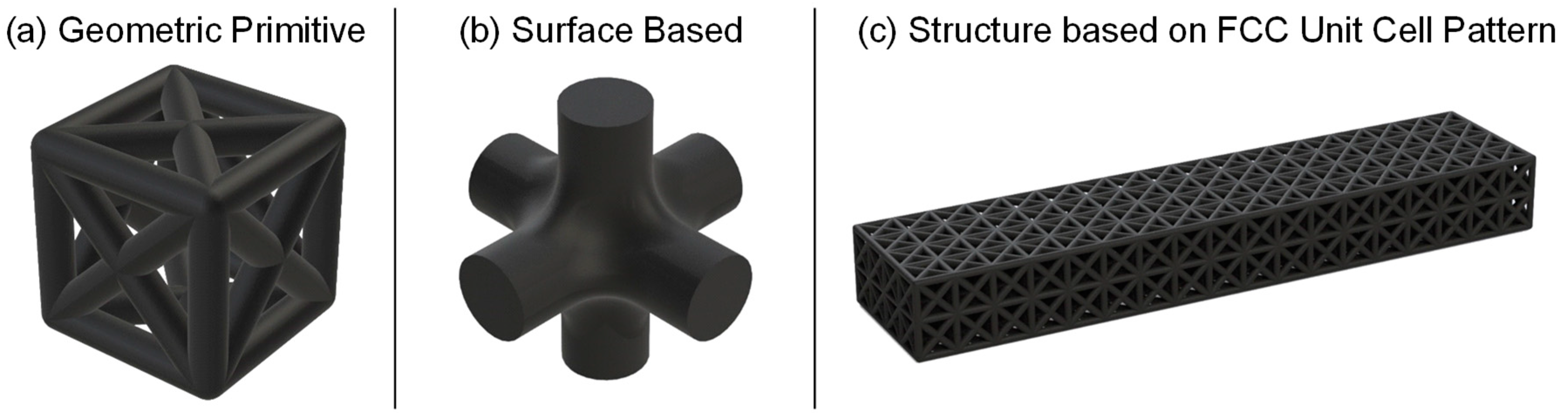
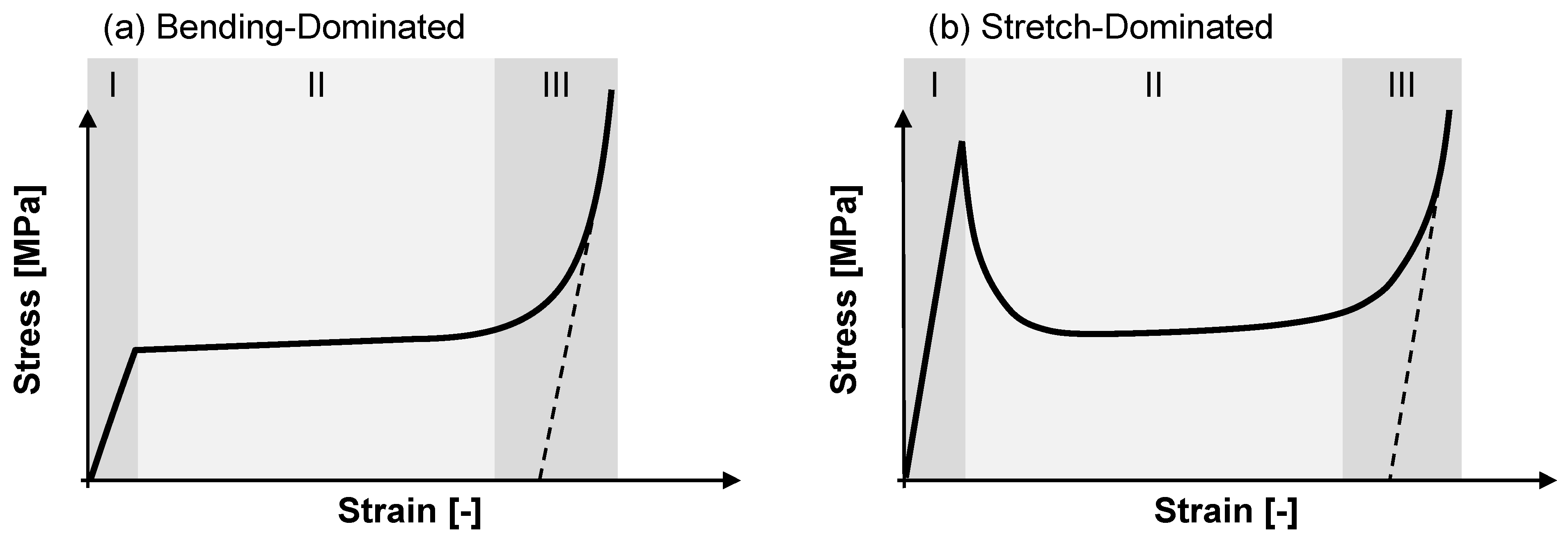
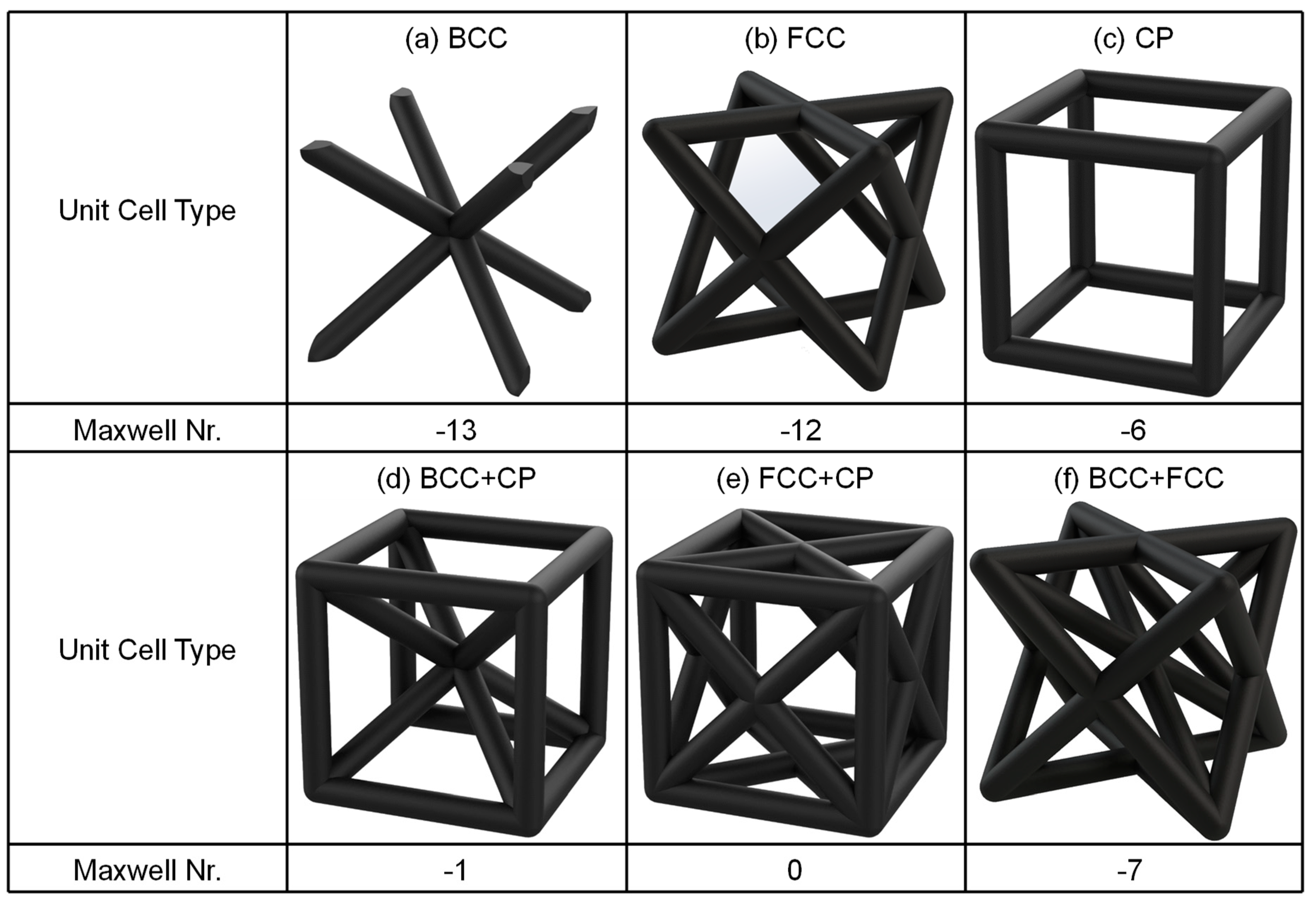
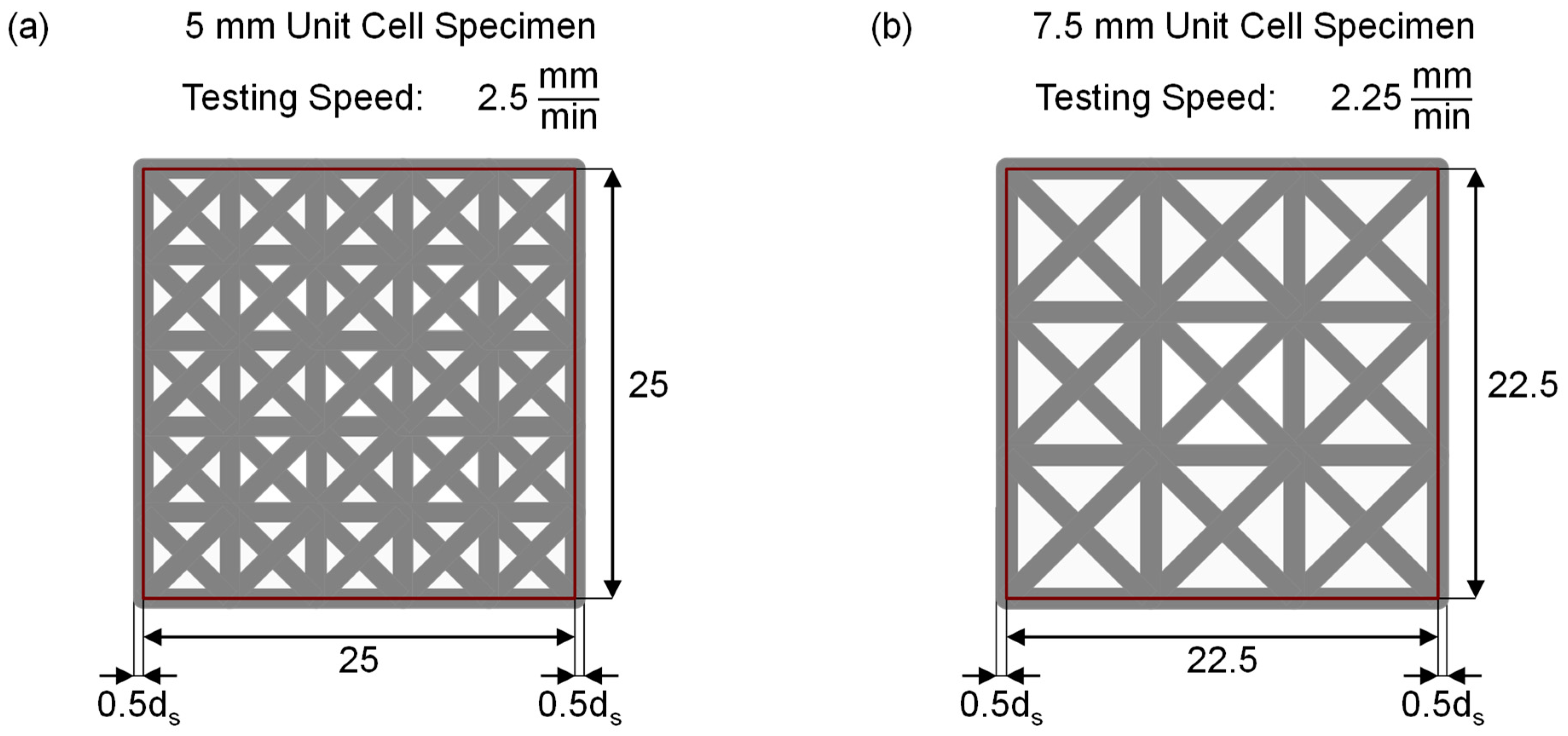
2.2. Lattice Structure Design

A lattice structure was designed to be used as sandwich cores. For simplicity, only unit cell-based lattice structures were considered. The lattice configurations were further reduced by only taking into consideration equilateral, geometric primitive unit cells.
Unit cell geometries meeting these criteria are shown in Figure 3. Figure 3a–c show the base configuration of Body-Centered Cubic (BCC), Face-Centered Cubic (FCC) and Cubic-Primitive (CP) unit cells, respectively. The unit cells shown in Figure 3d,e are combinations of these base configurations.
Sandwich structures with highly rigid mechanical properties were desired. Thus, in order to complement the mechanical properties of the sandwich structures, a stretch-dominated, stiff lattice behavior is required. Consequently, only unit cells with a Maxwell Number M ≥ 0 are suitable. The basic unit cell structures, shown in Figure 3a–c exhibit under-stiff behavior and are excluded. Similarly, the BCC+CP and BCC+FCC unit cells depicted in Figure 3d,f are excluded. Only the FCC+CP unit cell satisfied the above stated condition, as shown in Figure 3e. Therefore, an FCC+CP unit cell structure was chosen for all subsequent experimental investigations.
With the lattice design determined, two types of tests are performed: First, compressive testing of 3D-printed lattice structures without the fiber reinforcement, and second flexural testing of fully 3D-printed lattice sandwich structures and CFRP hybrid lattice sandwich structures.

2.2.1. Compression Testing

Compression testing was conducted to determine the mechanical behavior and characteristics of the 3D-printed lattice structure manufactured using DLS. Both of the investigated parameters, unit cell size and strut diameter, impact the geometry and change the relative density, and thus specific lattice characteristics.
Two cell edge lengths of 5 and 7.5 mm are used for the unit cell size in order to fit the specimen dimension with a whole-numbered amount. The second parameter, strut diameter, uses three parameter levels as shown in Table 2. The strut diameter for each unit cell size is selected based on the ratio of these parameters. Similar ratios result in similar relative densities. The respective values and specimen designations are shown in Table 2. The lattice structures are designed so that the ratios of diameter and unit cell size match for both unit cell sizes, as to guarantee comparability. The ratios used provide a balance between low relative density and supposed structural integrity. An intentional deviation from this pattern is specimen designation 5-0.5. With a strut–unit cell ratio of 0.1, the parameter set is used to estimate whether very low relative density lattice structures are possible.
The mechanical properties of the lattice structures are determined by conducting uniaxial compression tests in accordance to ASTM D1621 [26]. The specimen design stated in the standard was adapted to match the unit cell-based lattice structure. Based on square specimens with a cubic geometry, a design for each unit cell size was derived as depicted in Figure 4. For the 5-mm unit cell-based lattices, a specimen with a cubic side length of 25 mm was used (Figure 4a). In the case of a unit cell size of 7.5 mm, the specimen results in a side length of 22.5 mm, shown in Figure 4b. These lengths refer to the strut middle axis. Furthermore, the respective testing speeds are shown in Figure 4 [26]. As specified by ASTM D1621, the testing speed is equal to 10% of the specimen length. Before testing, a preload of 10 N was applied. Testing was performed using an Instron universal testing system 5930 series with a 30-kN 2580 series static load cell. For each parameter set, five specimens are tested.

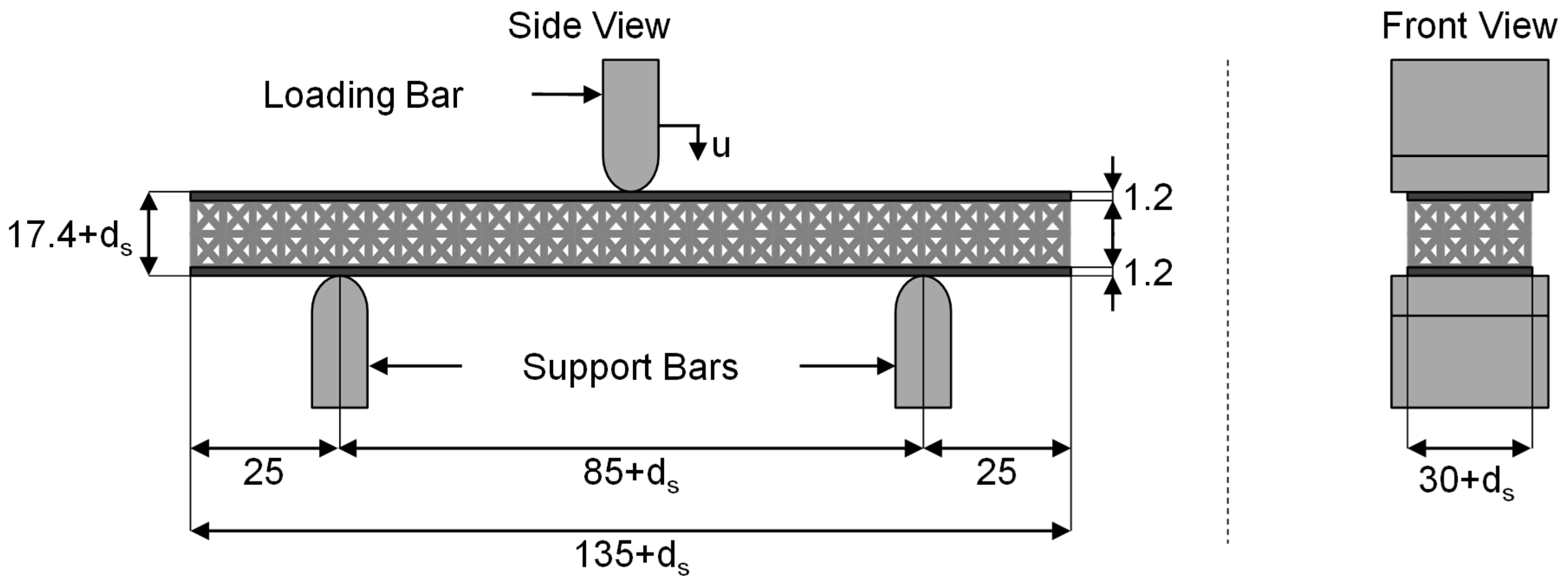
2.2.2. Flexural Beam Testing

An adapted three-point bending method based on ASTM D7249 was used. ASTM D7249 suggests a rectangular specimen with a width of 75 mm and a length of 600 mm. These dimensions are not compatible with the maximum build volume of the M1 printer (141 × 79 × 326 mm), so the specimen was scaled down [27,28]. A depiction of a hybrid lattice sandwich specimen, its measurements, and the testing set up are shown in Figure 5. The figure shows values referring to the strut middle axis. The respective strut diameter has to be added to these fixed values in order to reach the true measurements. Five layers of the CF prepreg reinforcement were used on the top and bottom surfaces to form the facesheets.
Flexural testing was conducted to measure the mechanical properties of hybrid lattice sandwich structures. Furthermore, the bonding quality between the 3D-printed lattice structure and CF prepreg is assessed to determine whether or not it poses a structural weakness. For this, hybrid bending specimens with different strut diameters were manufactured and tested under flexural bending following ASTM D7249.
Using results from the compression experiments, only the strut diameter of the lattice structures was varied. A 7.5-mm unit cell was chosen with strut diameters of 1.5, 1.875, and 2.25 mm. The unit cell size guaranteed a whole-numbered amount of unit cells in the specimen. As a benchmark for the hybrid lattice sandwich structures, the same flexural bending specimen geometry was tested without the CF reinforcement. The resulting design of experiments is shown in Table 3.
In order to improve the bonding between the 3D-printed part and CF prepreg, a surface is added to the top and bottom of the beam’s lattice core. The surface has a thickness of 0.2 mm to minimize its impact on the mechanical properties of the lattice while offering more surface area for bonding. The specimen was loaded with a constant testing speed of 1 mm/min. The same universal testing machine was used as for the compression tests. For each CF-reinforced parameter set, three specimens were tested, whereas four specimens are tested for each non-reinforced parameter set.

2.3. Manufacturing of Hybrid Lattice Sandwich Structures

The first step in the manufacturing process is the DLS printing process. For this, the manufacturer’s recommended EPX81 profile is used, with a sliced layer thickness of 100 µm. Compressive specimens are oriented so that the bottom side is attached to the printers build stage. Flexural specimens are oriented lengthwise with the long side edge being attached to the build stage. Finished parts are removed from the build stage using a razor. Post processing of the printed parts consists of resin removal through iterative part spinning in an immersion of cleaning solution.
The manufacturing of flexural specimen consists of the thermal B-stage co-curing of EPX81 and the CF-Prepreg after the UV printing process. First, five uncured CF prepreg layers were stacked on the top and bottom surface of the DLS-printed lattice core. Next, the finished layup was packed in a vacuum bag and co-cured using the supplier recommended curing temperature profile for the EPX81 as shown in Figure 6 [24].
After the completion of the curing cycle, the specimen was slowly cooled, demolded, and manually cleaned. An overview of finished flexural beam specimens is given in Figure 7.

3. Results

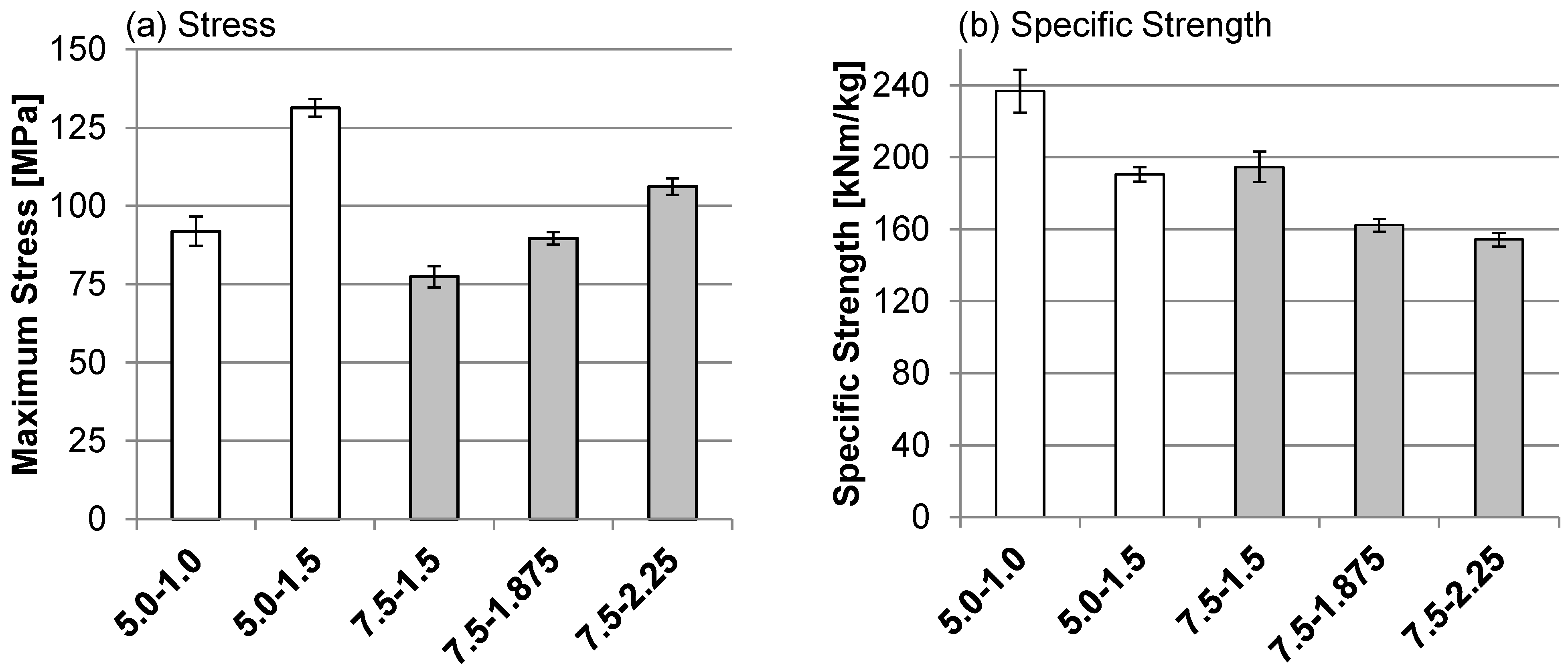
3.1. Mechanical Characterization of DLS Lattice Structures

The average maximum compressive stress of the DLS lattice structures reached before failure and the average specific strength are shown in Figure 8a,b. The results are compared to the respective parameter set. In order to compute the stress from the recorded compressive test data, the minimal area of the specimen cross-section was used. The specific strength is the ratio of maximum strength and lattice density and is used to normalize the strength in regard to the specimen mass. Error bars indicate one standard deviation. No results for parameter set 5-0.5 can be presented, as the specimen were severely damaged due to build plate adhesion forces when removing them from the build plate after printing as shown in Figure 9.
Figure 8a shows that the highest compressive strength of 131 MPa is reached by parameter set 5.0-1.5. The second strongest parameter set, 7.5-2.25, reaches a compressive stress of 106 MPa. As such, smaller unit cell sizes yield higher maximum stresses compared to larger unit cells at the same relative density. This conclusion is further reinforced by the same trend when comparing parameter set 5.0-1.0 and 7.5-1.5.
This behavior can be explained by the higher number of unit cells the specimen consists of due to the smaller unit cell sizes. This in turn leads to higher stress allocation, as more overall struts are available. Furthermore, an increase in strut diameter is followed by an increase in maximum compressive strength. The progression appears to be linear, with an average increase in compressive strength by 17% based on a strut diameter increase of 0.5 mm. Finally, the low standard deviation for each parameter set with regards to the maximum stress indicates high consistency of the mechanical properties of DLS-printed lattice structures.
The specific strength of each parameter set was calculated, and the results are shown in Figure 8b. The highest relative strength is reached by parameter set 5.0-1.0 with a value of 236 kNm/kg. The second highest specific strength is observed for specimen with a unit cell size of 7.5 mm and a strut diameter of 1.5 mm at 194 kNm/kg. We conclude that lattice structures with the lowest strut diameter to unit cell size ratio and thus relative density show the highest specific strength. The findings confirm the lightweight potential of these DLS-printed lattice structures.

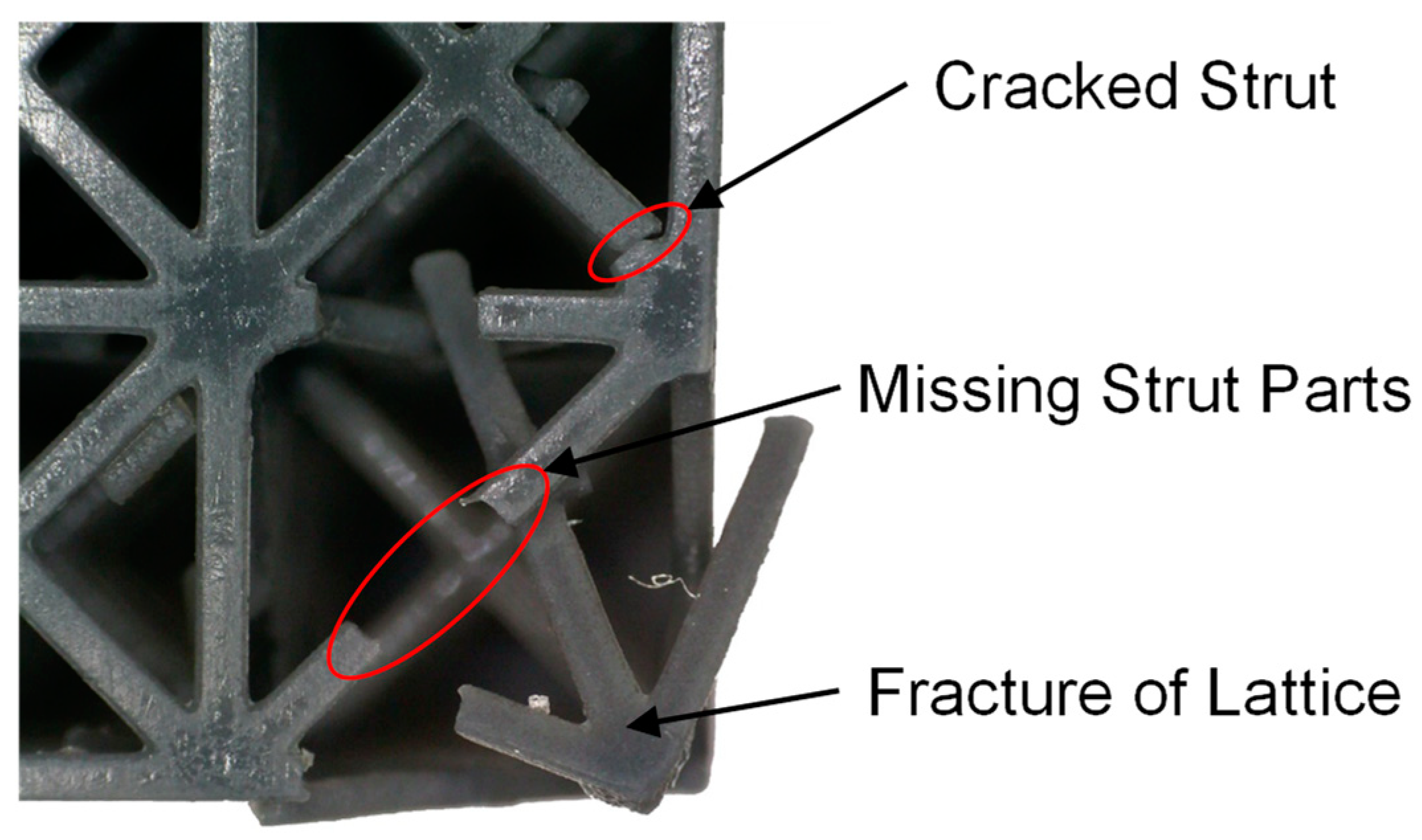
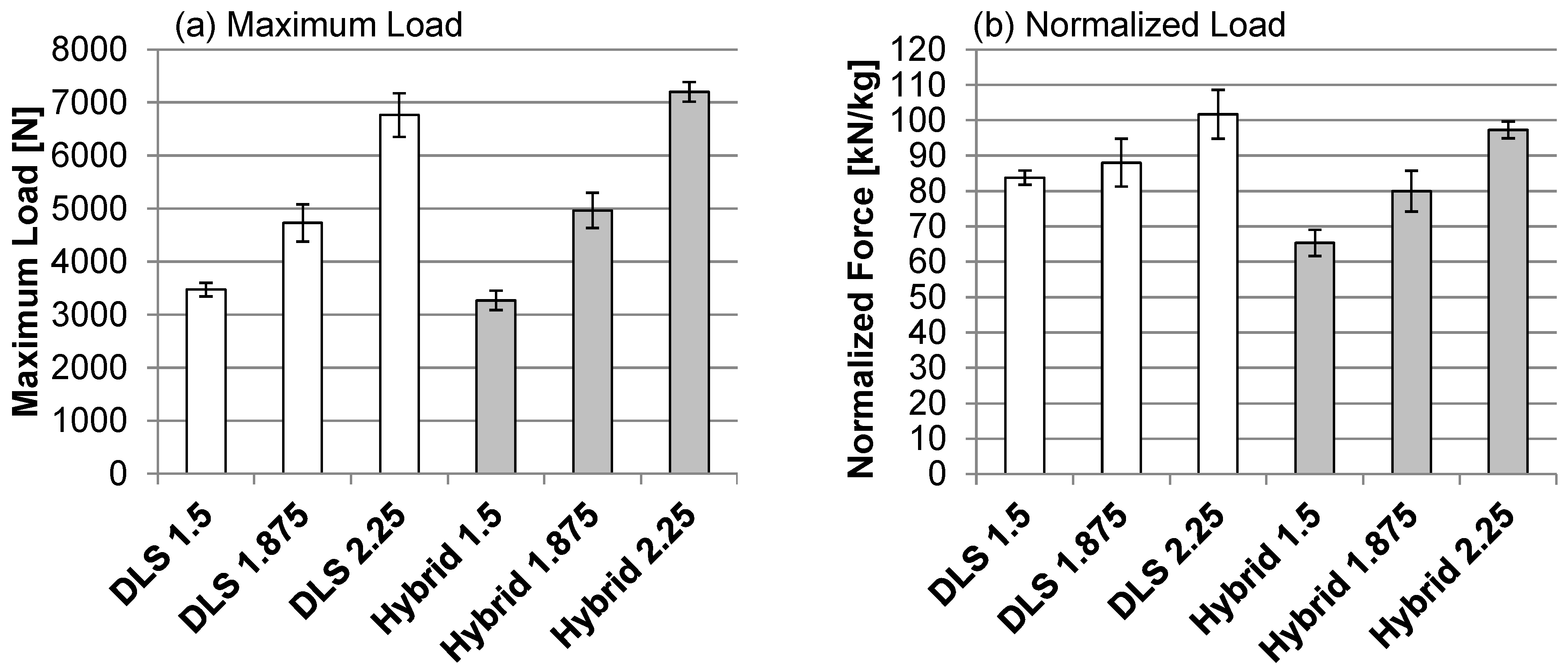
3.2. Flexural Testing of Hybrid Lattice Sandwich Structure

Figure 10a shows the average maximum load at failure for each parameter set for both the DLS lattice structures and hybrid lattice structures, with error bars indicating one standard deviation. The hybrid lattices with the CF reinforcement and the DLS lattice structures without the CF reinforcement fail at approximately the same maximum load. The highest loads are reached by hybrid parts with a strut diameter of 2.25 mm, which fail at 7.2 kN. The DLS parts with a strut diameter of 2.25 mm fail at a load of 6.9 kN, which is a difference within the range of one standard deviation. The failures occur in the epoxy lattice structure, which implies that the strength of both specimen types is dictated by the maximum strength of the epoxy lattice core.
A second observation is the linear relationship between strut diameter, and thus relative density, and maximum load. This applies for both variations of the sandwich structures. The results follow the observations made for the compression tests. Furthermore, both the hybrid lattices and standard DLS lattice structures show brittle behavior and fail instantly upon reaching the maximum load. This behavior confirms that stretch-dominated lattice structures are suitable for use in sandwich structures where stiff and strong material behavior is required.
The results of the flexural beam tests were normalized by dividing them by the respective specimen weight, shown in Figure 10b. Regarding the normalized loads, the values for the standard DLS lattice structures are generally higher compared to the hybrid lattice structures with the CF reinforcement. The highest normalized load is reached by the DLS specimen with a strut diameter of 2.25 mm at a value of 101 kN/kg. This is followed by the hybrid specimen with a strut diameter of 2.25 mm at 97 kN/kg. While these two values do not significantly differ, a higher divergence is observed for lower strut diameters. An explanation for this result is a comparatively higher mass of hybrid specimens due to the higher density of the CF facesheet layers.
The mode of failure for the DLS lattice structures and the hybrid lattice sandwich structures is shown in Figure 11a,b, respectively. For the standard lattices, a change in the angle of the failure can be observed. While the angle of fracture of a strut diameter of 1.5 mm is approximately 30°, at 1.875 mm, the angle is 50° and 90° for 2.25 mm. This indicates a shift in failure mode from shear to flexural tensile failure with an increase in strut diameter. For all hybrid lattice sandwich structures, failure occurs at an angle of 45° in the core region. This indicates core shear failure, as shown in Figure 11b. The observation further reinforces the assessment of the lattice strength being the limiting factor for the maximum load of hybrid lattice sandwich structures. In turn, the results confirm good bonding strength between the DLS epoxy lattice core and CF reinforcement.
The flexural stiffness determined by three-point bending is shown in Figure 12. It is evident that the stiffness of hybrid structures is considerably higher than the stiffness of the standard DLS parts. The maximum stiffness is reached by hybrid parts with a strut diameter of 2.25 mm at 4200 kN/m. The same lattice configuration for the DLS specimen only yields about half the stiffness at 2300 kN/m. The high stiffness further confirms the high potential for structural lightweight parts of hybrid 3D-printed epoxy lattice core and CF-reinforced sandwich structures.

4. Conclusions

An FCC+CP unit cell topology was designed based on the requirements identified for sandwich structures. Facilitating this lattice structure, compression specimens were designed and tested. The topology proves to be stretch dominated and shows mechanical strength and stiffness sufficiently high to be used as sandwich core structures at low relative densities. Higher strut diameters yield better absolute mechanical properties at the cost of a higher relative density and total mass, as reflected by a decrease in specific strength. Moreover, smaller unit cell sizes result in better mechanical properties compared to larger unit cells. However, very low relative density lattice structures could not be removed from the build plate without damage to the struts. Thus, such structures are not consistently manufacturable. In conclusion, the lattice structures used in this study show a high structural efficiency and can be applied to hybrid lattice sandwich structures.
Hybrid lattice sandwich structures are successfully manufactured using an adapted manufacturing process. The mechanical behavior of these structures is evaluated and compared to the corresponding geometries of the DLS-printed parts without CF reinforcement. It is shown that high strength and stiffnesses can be reached by hybrid lattice sandwich structures, while maintaining low weight. This makes such structures suitable for the application as lightweight structural components. The bonding strength between the DLS lattice core and CF prepregs is suitable to sustain high loads in bending. The overall strength of the hybrid parts is limited by the strength of the DLS epoxy lattice structure, demonstrated by the similar load at failure of the hybrid part and the DLS part. An optimization of the lattice topology could further improve the strength of these structures.
The overall conclusion of these experiments is that the co-curing of the 3D-printed epoxy parts using DLS and CF prepreg reinforcement is possible. Furthermore, the manufacturing of hybrid lattice sandwich structures is demonstrated. The resulting sandwich structures yield high mechanical properties and light weight.
Future research can be conducted on improving the properties of the lattice sandwich core. One approach could be the optimization of the sandwich lattice core by using proposed lattice designs found to yield good mechanical properties, for example octet-truss lattices [29,30,31]. Another approach is the optimization of lattice topology based on a given load case. The implementation of additional functions into the lattice core is also possible. Based on the high degree of freedom given by additive manufacturing, this could include fluid channels, cable routing or foam pockets for insulation.

Author Contributions

Conceptualization, T.A.O., J.A. and A.J.R.; Methodology, J.A.; Formal Analysis, J.A.; Investigation, J.A.; Resources, A.L.Q. and S.J.M.; Data Curation, A.J.R. and J.A.; Writing-Original Draft Preparation, J.A.; Writing-Review & Editing, A.J.R., V.D., A.L.Q., S.J.M. and T.A.O.; Visualization, J.A.; Supervision, T.A.O.; Project Administration, A.J.R.

Acknowledgments

This material is based upon work supported by the National Science Foundation Graduate Research Fellowship Program under Grant No. DGE-1747503. Any opinions, findings, and conclusions or recommendations expressed in this material are those of the authors and do not necessarily reflect the views of the National Science Foundation. Additionally, support was also provided by the Graduate School and the Office of the Vice Chancellor for Research and Graduate Education at the University of Wisconsin-Madison with funding from the Wisconsin Alumni Research Foundation. The authors would like to thank Krishnan Suresh at the University of Wisconsin-Madison for generating the lattice designs, as well as Daniel Miller for the material and design advice. Support for the DLS printing at the University of North Carolina was provided through a sponsored research program with Carbon, Inc. of Redwood City, CA.

Conflicts of Interest

The authors declare no conflict of interest.

References

  1. Herrmann, A.T.; Zahlen, P.C.; Zuardy, I. Sandwich Structures Technology in Commercial Aviation; Springer: Dordrecht, The Netherlands, 2005; ISBN 1-4020-3444-X. [Google Scholar]
  2. Eckstein, L.; Schmitt, F.; Hartmann, B. Leichtbau bei Elektrofahrzeugen. ATZ-Automob. Z. 2010, 112, 788–795. [Google Scholar] [CrossRef]
  3. The European Parliament and the Council of the European Union Regulation (EU) No 333/2014 of the European Parliament and of the Council of 11 March 2014 Amending Regulation (EC) No 443/2009 to Define the Modalities for Reaching the 2020 Target to Reduce CO2 Emissions from New Passenger Cars; European Union: Strassburg, France, 2014.
  4. Xiong, J.; Du, Y.; Mousanezhad, D.; Eydani Asl, M.; Norato, J.; Vaziri, A. Sandwich Structures with Prismatic and Foam Cores: A Review. Adv. Eng. Mater. 2019, 21, 1800036. [Google Scholar] [CrossRef]
  5. Allen, H.G. Analysis and Design of Structural Sandwich Panels: The Commonwealth and International Library: Structures and Solid Body Mechanics Division; Pergamon: Oxford, UK, 1969; ISBN 978-0-08-012870-2. [Google Scholar]
  6. SAND.CORe Co-ordination Action on. Best Practice Guide for Sandwich Structures in Marine Applications; Newcastle University: Newcastle upon Tyne, UK, 2013. [Google Scholar]
  7. Türk, D.-A.; Kussmaul, R.; Zogg, M.; Klahn, C.; Spierings, A.; Könen, H.; Ermanni, P.; Meboldt, M. Additive manufacturing with composites for integrated aircraft structures. In Proceedings of the SAMPE, Long Beach, CA, USA, 23–26 May 2016. [Google Scholar]
  8. Osswald, T.A. Understanding Polymer Processing: Processes and Governing Equations, 2nd ed.; Hanser Publishers and Hanser Publications: Munich, Germany; Cincinnati, OH, USA, 2017; ISBN 978-1-56990-647-7. [Google Scholar]
  9. Gebhardt, A.; Hötter, J.-S. Additive Manufacturing: 3D Printing for Prototyping and Manufacturing; Hanser Publishers and Hanser Publications: Munich, Germany; Cincinnati, OH, USA, 2016; ISBN 978-1-56990-582-1. [Google Scholar]
  10. Li, T.; Wang, L. Bending behavior of sandwich composite structures with tunable 3D-printed core materials. Compos. Struct. 2017, 175, 46–57. [Google Scholar] [CrossRef]
  11. Beyer, C.; Figueroa, D. Design and Analysis of Lattice Structures for Additive Manufacturing. J. Manuf. Sci. Eng. 2016, 138, 121014. [Google Scholar] [CrossRef]
  12. Schaedler, T.A.; Carter, W.B. Architected Cellular Materials. Annu. Rev. Mater. Res. 2016, 46, 187–210. [Google Scholar] [CrossRef]
  13. Tao, W.; Leu, M.C. Design of lattice structure for additive manufacturing. In Proceedings of the International Symposium on Flexible Automation: ISFA 2016, Cleveland, OH, USA, 1–3 August 2016. [Google Scholar]
  14. Ashby, M.F. The properties of foams and lattices. Philos. Trans. A Math. Phys. Eng. Sci. 2006, 364, 15–30. [Google Scholar] [CrossRef] [PubMed]
  15. Tang, Y.; Dong, G.; Zhou, Q.; Zhao, Y.F. Lattice Structure Design and Optimization with Additive Manufacturing Constraints. IEEE Trans. Autom. Sci. Eng. 2017, 15, 1546–1562. [Google Scholar] [CrossRef]
  16. Wadley, H.N.G. Multifunctional periodic cellular metals. Philos. Trans. R. Soc. Math. Phys. Eng. Sci. 2006, 364, 31–68. [Google Scholar] [CrossRef] [PubMed]
  17. Rashed, M.G.; Ashraf, M.; Mines, R.A.W.; Hazell, P.J. Metallic microlattice materials: A current state of the art on manufacturing, mechanical properties and applications. Mater. Des. 2016, 95, 518–533. [Google Scholar] [CrossRef]
  18. Mazur, M.; Leary, M.; McMillan, M.; Sun, S.; Shidid, D.; Brandt, M. Mechanical properties of Ti6Al4V and AlSi12Mg lattice structures manufactured by Selective Laser Melting (SLM). In Laser Additive Manufacturing; Woodhead Publishing: Cambridge, UK, 2017; pp. 119–161. [Google Scholar]
  19. Janusziewicz, R.; Tumbleston, J.R.; Quintanilla, A.L.; Mecham, S.J.; DeSimone, J.M. Layerless fabrication with continuous liquid interface production. Proc. Natl. Acad. Sci. USA 2016, 113, 11703–11708. [Google Scholar] [CrossRef] [PubMed]
  20. De Simone, J.M.; Ermoshkin, A.; Samulski, E.T. Method and Apperatus for Three-Dimensional Fabrication. US Patent 9,498,920, 22 November 2016. [Google Scholar]
  21. Tumbleston, J.R.; Shirvanyants, D.; Ermoshkin, N.; Janusziewicz, R.; Johnson, A.R.; Kelly, D.; Chen, K.; Pinschmidt, R.; Rolland, J.P.; Ermoshkin, A.; et al. Additive manufacturing. Continuous liquid interface production of 3D objects. Science 2015, 347, 1349–1352. [Google Scholar] [CrossRef] [PubMed]
  22. Epoxy Technology Inc. B-Stage Epoxy; Epoxy Technology Inc.: Billerica, MA, USA, 2012. [Google Scholar]
  23. Carbon, Inc. CarbonResin EPX 81; Carbon, Inc.: Redwood, CA, USA, 2017. [Google Scholar]
  24. Carbon, Inc. CarbonResin EPX 81 Biocompatibility; Carbon, Inc.: Redwood, CA, USA, 2017. [Google Scholar]
  25. Mitsubishi Chemical Carbon Fiber and Composites, Inc. EP4030 Epoxy Resin System; Mitsubishi Chemical Carbon Fiber and Composites, Inc.: Irvine, CA, USA, 2017. [Google Scholar]
  26. ASTM D1621 Test Method for Compressive Properties of Rigid Cellular Plastics; ASTM International: West Conshohocken, PA, USA, 2016.
  27. ASTM D7249 Test Method for Facing Properties of Sandwich Constructions by Long Beam Flexure; ASTM International: West Conshohocken, PA, USA, 2016.
  28. www18 Carbon Hardware. Available online: https://www.carbon3d.com/hardware (accessed on 18 February 2018).
  29. Deshpande, V.S.; Fleck, N.A.; Ashby, M.F. Effective properties of the octet-truss lattice material. J. Mech. Phys. Solids 2001, 49, 1747–1769. [Google Scholar] [CrossRef]
  30. Dong, L.; Deshpande, V.; Wadley, H. Mechanical response of Ti-6Al-4V octet-truss lattice structures. Int. J. Solids Struct. 2015, 60–61, 107–124. [Google Scholar] [CrossRef]
  31. Saigal, A.; Tumbleston, J.; Vogel, H.; Fox, C.; Mackay, N. Mechanical Response of Octahedral and Octet-Truss Lattice Structures Fabricated Using the CLIP Technology; DEStech Publications, Inc.: Lancaster, PA, USA, 2016. [Google Scholar]
Figure 1. (a) Geometric primitives and (b) surface-based unit cells used in the generation of (c) lattice structures.
Jcs 03 00053 g001
Figure 2. Compression behavior of bending-dominated (a) and stretch-dominated (b) lattice structures
Jcs 03 00053 g002
Figure 3. Unit cell types considered for the lattice generation with the respective Maxwell Number. (a) Body-Centered Cubic (BCC); (b) Face-Centered Cubic (FCC); (c) Cubic-Primitive (CP); (d) Body-Centered Cubic combined with Cubic-Primitive (BCC+CP); (e) Face-Centered Cubic combined with Cubic-Primitive (FCC+CP); (f) Body-Centered Cubic combined with Face-Centered Cubic (BCC+FCC).
Jcs 03 00053 g003
Figure 4. Schematic depiction of the (a) 5-mm unit cell, and (b) 7.5-mm unit cell compression test specimen and the respective loading speeds. The strut diameter is designated as ds.
Jcs 03 00053 g004
Figure 5. Set up of three-point bending and measurements of test specimen in accordance to ASTM D7249. The strut diameter is designated as ds.
Jcs 03 00053 g005
Figure 6. EPX81 curing temperature cycle [24].
Jcs 03 00053 g006
Figure 7. Finished flexural beam specimens for (a) hybrid specimens and (b) Digital Light Synthesis (DLS)-printed specimen.
Jcs 03 00053 g007
Figure 8. Maximum compressive stress (a) and specific strength (b) of tested parameter sets.
Jcs 03 00053 g008
Figure 9. Example of damaged lattice in 5-0.5 DLS specimen.
Jcs 03 00053 g009
Figure 10. Maximum load (a) and mass-normalized load (b) before failure during flexural beam test.
Jcs 03 00053 g010
Figure 11. Mode of failure for the DLS lattice structures (a) and hybrid sandwich structure (b).
Jcs 03 00053 g011
Figure 12. Flexural stiffness of the DLS and hybrid lattice structures with CF reinforcement.
Jcs 03 00053 g012
Table 1. Material properties of EPX81 and EP4030; mechanical properties are given in fiber direction [23,25].
Material PropertyEPX81EP4030
Tensile Strength (MPa)88 ± 32370
Tensile Modulus (GPa)3140 ± 105146
Flexural Strength (MPa)119 ± 211720
Flexural Modulus (MPa)3250 ± 45140
Table 2. Specimen designation based on unit cell size and strut diameter as well as ratio of strut diameter and unit cell size.
Specimen DesignationUnit Cell Size (mm)Strut Diameter (ds) (mm)Ratio of Strut Diameter and Unit Cell Size
5-0.550.5000.10
5-1.01.0000.20
5-1.51.5000.30
7.5-1.57.51.5000.20
7.5-1.8751.8750.25
7.5-2.252.2500.30
Table 3. Specimen designation based on material and strut diameter.
Specimen DesignationFace Sheet MaterialStrut Diameter (ds) (mm)Ratio of Strut Diameter and Unit Cell Size
Hybrid 1.55 layers
CF prepreg
1.5000.20
Hybrid 1.8751.8750.25
Hybrid 2.252.2500.30
DLS 1.5EXP811.5000.20
DLS 1.8751.8750.25
DLS 2.252.2500.30

