
Abrasive Water Jet Milling as An Efficient Manufacturing Method for Superalloy Gas Turbine Components

1
RISE Research Institutes of Sweden AB, 431 53 Mölndal, Sweden
2
GKN Aerospace Engine Systems AB, 461 38 Trollhättan, Sweden
*
Author to whom correspondence should be addressed.
J. Manuf. Mater. Process. 2022, 6(5), 124; https://doi.org/10.3390/jmmp6050124
Submission received: 20 September 2022
/
Revised: 7 October 2022
/
Accepted: 19 October 2022
/
Published: 20 October 2022
(This article belongs to the Special Issue Smart and Advanced Manufacturing)
Abstract
:In order to improve efficiency when manufacturing gas turbine components, alternative machining techniques need to be explored. In this work, abrasive water jet (AWJ) machining by milling has been investigated as an alternative to traditional milling. Various test campaigns have been conducted to show different aspects of using AWJ milling for the machining of superalloys, such as alloy 718. The test campaigns span from studies of individual AWJ-milled tracks, multi-pass tracks, and the machining of larger components and features with complex geometry. In regard to material removal rates, these studies show that AWJ milling is able to compete with traditional semi/finish milling but may not reach as high an MRR as rough milling when machining in alloy 718. However, AWJ milling requires post-processing which decreases the total MRR. It has been shown that a strong advantage with AWJ milling is to manufacture difficult geometries such as narrow radii, holes, or sharp transitions with kept material removal rates and low impact on the surface integrity of the cut surface. Additionally, abrasive water jet machining (AWJM) offers a range of machining possibilities as it can alter between cutting through and milling. The surface integrity of the AWJM surface is also advantageous as it introduces compressive residual stress but may require post-processing to meet similar surface roughness levels as traditional milling and to remove unwanted AWJM particles from the machined surface.
1. Introduction
Many large and complex gas turbine components made from various “difficult-to-machine” alloys, in particular heat-resistant superalloys, are very resource-demanding, not the least in the material removal stages of component manufacturing. Therefore, a strong driving force exists within the manufacturing community for such components, to improve process efficiency for applications comprising these materials and to develop entirely new and dedicated manufacturing concepts. In order to find such concepts, new and less exploited manufacturing alternatives are of interest for further studies such as electrochemical machining, electrical discharge machining, or abrasive water jet machining. The present work focuses on abrasive water jet machining (AWJM). This method is basically a controlled erosion process that utilizes abrasives that become energized when mixed into a jet of highly pressurized water directed toward the workpiece as described by Folkes [1].
The literature shows an increasing interest in AWJM, especially for processing difficult-to-machine materials such as superalloys, Folkes [1] and Korat et al. [2]. The AWJM method has mainly been used to cut through the material (parting), and most published research relates to producing correct geometry with a straight cut and low surface roughness. AWJM for the purpose of milling is less exploited but may offer greater possibilities than traditional milling, particularly in demanding applications, since the penetration depth and effectively the cutting mode could be alternated between milling and cutting through by just simply changing the machining settings. This could become a very efficient alternative for many gas turbine applications. In particular, those where difficult-to-machine materials are to be processed into intricate shapes, which was also identified in the review by Korat et al. [2]. That review also spotted a future trend for the use of AWJM for precision machining in applications such as polishing, drilling, turning, or milling. Such trends were also discussed and exemplified with machining tests by Folkes [1]. Alberdi et al. showed a novel investigation of hole-making using AWJM of CFRP/Ti-6Al-4V stacks [3]. However, the mentioned research indicated further process development.
1.1. The Abrasive Water Jet Technology
Optimizing AWJM cutting through efficiency and the achieved quality of the processed surface was studied by both Öjmetrz [4] and Kovacevic et al. [5] for sheet materials. In these early works, the impact of the main process parameters was studied such as the water jet pressure, water jet flow rate, abrasive size, abrasive mass flow, stand-off distance, and properties of the workpiece material.
In order to further study the fundamentals of the processing parameters, various studies using FE simulation have been conducted. Wang investigated the particle velocity difference in directions across and along the cut [6]. The erosion process was FE-simulated by Klocke et al. to predict the material removal rates [7]. Kumar et al. developed a multi-particle model to study the effect of particle impact angle and velocity [8]. Additionally, the water beam characteristics were further studied by Guha et al. with numerically verified models of the water beam for cleaning, revealing the beam and workpiece interaction [9].
1.2. Abrasive Water Jet Milling
AWJM for milling was investigated in early work by Hashish, who studied the milling of different types of materials such as aluminum, titanium, and alloy 718 [10,11]. Öjmertz also investigated the possibilities and limitations of the AWJM milling method [4]. However, much of this knowledge is dated and the results are not accessible to the current research field.
AWJM for milling in its simplest form will produce trenches, which placed in a predefined pattern may generate pockets in the workpiece material. Such work was shown by Escobar-Palafox et al. who performed pocket milling tests of Inconel 718 with the target to create straight sidewalls [12]. It was found that the undercut effect, sidewall angle to the entrance plane of the beam into the workpiece, could be controlled by the water jet pressure and path-planning strategy, trench step-over, but the nozzle diameter also influenced. On a similar topic, Alberdi et al. investigated the kerf geometry when slot milling in an aluminum alloy in order to develop a predictive model [13].
One suitable application for AWJM milling is the machining of thin-walled components, which are prone to distortion due to internal residual stresses in the starting material of larger castings. Such work was shown by Wanner et al. who investigated a hybrid machining concept, combining AWJM for cutting and milling to manufacture a thin-walled aluminum component [14]. It was shown that distortion was suppressed by using AWJM in the first machining step to reduce the vibrations, which are often a common limitation of traditional milling operations.
However, for more complex geometries, distinct control of the water beam is required, which involves adjustment and the possibility to program the beam motion relative to the trajectory path in the workpiece material. Thus, predictive modeling is required to determine how to control the depth of cut as shown by Aydin et al., who used a Taguchi model for predicting machining in granite [15]. A predictive model for AWJM pocket milling was developed by Deam et al. [16]. This model showed the ability to catch fluctuations from the erosion process that results in unwanted local curvatures, which might not completely be eliminated. As suggested by Kong et al., the seamless milling of pockets could be achieved with the clever design of the water jet tool path [17]. The different developed models showed that the depth of cut increased with increased abrasive mass flow rate and water pressure. Additionally, Escobar-Palaflox et al. realized that the water jet pressure and depth of cut had a non-linear relationship, which therefore requires a deep understanding of the beam interaction with the workpiece in order to control the depth of cut during AWJM [12]. Further, the great impact of the nozzle diameter, feed rate, and abrasive mass on the depth of cut was shown. Therefore, it was suggested by Rabani et al. to use an iterative learning control tool to improve prediction and eventually correction of the AWJM process parameters [18]. The results showed more than double the precision after four iterations of machining, which is paving the way for future machining of free-form surfaces. Rabani et al. also proposed a method to control the jet penetration in AWJM milling by monitoring the erosion in the workpiece by acoustic emission [19]. This was exemplified by the machining of Ti-6Al-4V, where the jet feed velocity was adjusted, enabling the jet penetration to be kept constant. This also enables close-loop control of the process. In order to find the optimal parameters, Yuan et al. developed a Box-Behnken design model for the machining of circular pockets [20]. The verified model showed that the best possible surface quality, in that case, was achieved using a pressure of 195 MPa, a traverse speed of 425 mm/min, a stand-off distance of 3.5 mm, and a mass flow rate of 70 g/min.
The efficiency of AWJM for milling has not been investigated extensively but one example was shown by Hashish who concluded that the stand-off distance was crucial for determining the resulting material removal rates (MRRs) [10]. The optimal distance was similar to the one used in the regular cutting of deep kerfs, and it was also shown that a larger stand-off distance decreases the MRR since the beam interaction must cover a larger part of the workpiece surface, which results in a correspondingly lower erosion effect. However, a higher abrasive flow rate increased the MRR. It was concluded that using a traverse speed of 16 mm/s and a stand-off distance kept close to 12 mm achieved a high MRR. Fowler et al. showed that the material removal rate decreased with higher traverse speed, which also increased the surface roughness but reduced the surface waviness when machining Ti-6Al-4V [21]. The authors also pointed out that the hardness of the AWJM media influenced the material removal rate. The mesh 80 garnet resulted in the highest MRR of 20·10−6 kg/s, relatively independent of the traverse speed.
One of the major drawbacks of AWJM for milling is the roughness and waviness generated by the erosion process. The arithmetic mean height (Ra, Sa) is typically in the range of 4–6 µm which could be further improved if the surface is post-processed [22,23,24]. On this topic, Vasanth et al. reported that the surface topography was mainly determined by the abrasive flow and stand-off distance [25]. However, in that research, it was also shown that the surface waviness is more difficult to resolve and might require a secondary machining operation in the worst case. Another important observation is that the surface waviness could not be completely removed by subsequent passes but on the contrary, will become more pronounced. It has further been concluded by Öjmertz that both surface roughness and waviness are dependent of the milling depth [22]. However, Fowler et al. showed that the waviness could be improved by using a high traverse speed [21]. Alternatively, surface roughness and waviness could be controlled by the selection of a beam side step. The strategy of tool paths and side steps was investigated by Alberdi et al. when AWJM milling an aluminum 7075-T651 alloy [26]. The research focused on the development of a model to predict the tipping point of when the overlap could be observed. It was shown that in order to suppress increased roughness and waviness for subsequent AWJM slot milling, a lateral feed should be used as the shortest distance to a previously machined surface. Further, the research also pointed out the importance of the kinematics of the cutting head.
1.3. Surface Integrity after Abrasive Water Jet Machining
A major drawback with AWJM for milling is the abrasive embedment that occurs in the top layer of the eroded surface, which might be critical depending on how the surface is to be used. This was the main focus of the research by Fowler et al., who studied AWJ milling of Ti-6Al-4V [27]. It was shown that the impact of abrasive embedment is influenced by the traverse speed, jet impingement angle, milling direction, and grit size. It was shown that up to 40% of the AWJM milled surface contained embedded abrasives but it could be minimized by using high traverse speed with low impingement angles or by low traverse speed and jet impingement angles up to 45° in the backward direction [27]. Different abrasives were also investigated by Fowler et al., which showed that higher abrasive hardness resulted in higher material removal rates and increased surface roughness. The surface waviness could also be reduced for increased traverse speed, which is a key parameter for controlling the material removal rate. Boud et al. concluded that the morphology of the original particles has less influence on the erosion process but rather the morphology of the fragments of the fractured particles as they are mixed into the water jet beam and therefore determines the particle embedment and cut quality [28].
The resulting surface integrity after AWJM is typically a rather low surface roughness with a relatively high compressive residual stress on the surface. This has been shown for AWJM through cutting in related works [29,30]. However, contrary to the expected mechanical performance based on residual stresses and topography, several authors have shown low fatigue performance caused by local stress gradients caused by the abrasive particle embedment [31,32,33,34]. This implies that an AWJM surface requires post-processing in order to restore its surface integrity. Two possible concepts could be considered: either restore the surface by an alternative method where the abrasive particles are removed and the surface integrity is improved from local stress concentrations, or finish machining of the surface with conventional milling. Alternative post-processing could include abrasive water jet cleaning, i.e., as shown by Huang et al. [34]. Liao et al. further showed an interesting dual processing technique with AWJM machining followed by a surface modification process by means of peening [35]. This post-processing was conducted by mixing steel balls into the water beam, which peen the surface and introduce compressive residual stresses, and further, remove the striation texture by flattening the surface. However, this is quite a brave suggestion since one needs to consider how to handle the steel balls after the peening as they will spall the surface and fill the AWJM machine box. The other alternative is to restore the surface by a subsequent finish machining operation, which might be the most suitable alternative for an AWJM rough-milled surface.
The work related to AWJM for milling as a rough machining method is not mentioned at all in the existing literature whereas this work aims to investigate it. AWJ cutting is an established method as an alternative to contour cutting of sheet metal, but with the addition of advanced algorithms for material erosion, also has the potential as an alternative method to produce sculpted surfaces.
To summarize, previous investigations have shown that the technology has great potential for creating a surface with desirable properties, as the method has little or no thermal impact on the processed material. In addition, careful examinations of the surfaces have shown that the method generally gives low residual stresses, mainly compressive, but unfortunately also shows some side effects, such as residues of the abrasives sticking to the surface layer. Thus, some finishing (post-processing) of the final surfaces manufactured with this method is required.
1.4. Objective and Outline of the Paper
The efficiency of the traditional machining of alloy 718 has been shown by the authors of this work to be in the range of 6–10 cm3/min for roughing with ceramic milling, and 1–2 cm3/min for semi/finish milling with cemented carbide tools [36]. Additionally, it has been shown that for rough machining, a machining allowance typically in the order of 0.5 mm is needed to make sure that any detrimental effects of high tensile stresses or deformation are not present in the finished surface [37].
The main identified advantage of AWJM for milling is that the different milling operations, from rough to finish, could use the same set-up, allowing for the machining of complex geometries. However, to establish this as a viable process route, a deep knowledge of the impact of the main processing parameters and machining strategy needs to be determined. In this work, two possible manufacturing concepts of AWJM for milling are considered:
- Rough AWJM milling followed by finishing using traditional finish milling.
- Finish AWJM for milling to produce a close-to-final geometry but with a post-processing operation for the removal of abrasive particles.
The literature indicates that AWJ milling is mature but there are only a few reports on more advanced studies involving rough machining or the finishing of complex geometries. Therefore, in this work, the ability and efficiency of AWJM for milling have been evaluated for the manufacturing of gas turbine components of superalloys. This has been realized through three different test campaigns exploring AWJ for milling. The target has been to compare how these results measure against traditional milling.
The research approach in this work is divided into three parts. Part one is devoted to establishing clear relationships between the traverse speed, the nozzle distance, water jet pressure, and its distribution on the workpiece material. This work has been conducted using both single- and multi-pass machining.
The second part is devoted to applying this knowledge to AWJM for milling tests, aiming for future applications of manufacturing superalloy components for gas turbines with two concepts: AWJM rough milling and AWJM semi/finish milling. The former is considered a substitute for ceramic rough milling or turning whereas the latter is considered a substitute for finish milling.
The third part has been performed to verify the derived knowledge of AWJM on a complex geometry using AWJM rough and finish milling.
2. Materials and Methods
2.1. Material
Tests of the AWJM performance were conducted on samples with dimensions of 8 mm thickness and 40 × 300 mm wideness of wrought sheets of alloy 718 in an as-received condition, with the chemical content as seen in Table 1. AWJM tests were also conducted on a large cast alloy 718 ring with a hardness of 381 ± 22 HV. The ring was 25 × 50 mm in a cross-section with a diameter of 900 mm.
2.2. Experimental
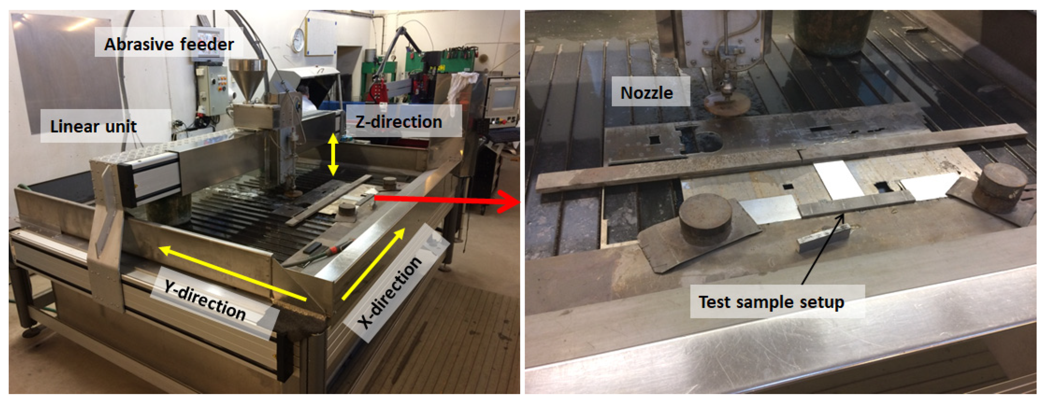
The AWJM machining tests were performed in two similar abrasive water jet cutting machines. Figure 1 and Figure 2 show an overview of the two machines and the experimental setups. Machine 1 is a non-branded machine, built in-house from standard AWJ components, and Machine 2 is an OMAX 60120. The individually used machining settings for the two machines are shown in Table 2. The selection of water jet nozzle diameter and abrasive mesh size was conducted on the basis of the recommended setting from the machine supplier. These parameters will have a direct effect on erosion (see Escobar-Palafox et al.) [12], but in the present work, the effects of other parameters are investigated. The selection of the two different machines was conducted on the basis of building knowledge of the interaction between a water jet beam and workpiece on a laboratory machine and then applying this to a standardized machine available on the market. The AWJ non-branded machine offered greater selection and adjustment of the machining settings whereas the second AWJ machine is a standardized production machine, for which available settings from the machine manufacturer were used. The non-branded machine motivates an investigation of the single erosion track characteristics to see if the effect is as expected.
Both machines are constructed such that the main machining area is partly immersed in deionized water, over which the abrasive water jet nozzle can be positioned in the X/Y-plane of the machine by means of a CNC-controlled gantry. The nozzle can be further adjusted perpendicular to the cutting plane through an additional axis for tilt and rotation. The Z-direction can be adjusted depending on the height of the material to be cut. The workpiece is fixtured to the machine such that the water in the tank below prevents the beam to travel any further.
The abrasive action is achieved by letting a beam of highly pressurized water pass through a jewel orifice, whereafter it enters into a mixing chamber and thereby creates a partial vacuum, as seen in the schematic overview in Figure 3. An abrasive medium feeder dispends the medium into a feed channel from which the abrasive is drawn into the mixing chamber by the vacuum. The abrasives are carried at the periphery of the water beam and exit through a focusing nozzle. The abrasive particles strike the workpiece material and interact by erosion and shearing. The cutting is performed either by moving the focused water beam or by manipulating the workpiece on a movable X/Y table.
2.3. Evaluation Methods
The surface topography and geometry after AWJ milling was measured using confocal fusion and coherence scanning interferometry (CSI) with a Sensofar S Neox instrument. Measurements were conducted over a suitable size to cover the general topography of the surface, including both its roughness and waviness features. The choice of measurement technique and magnifications set the lateral resolution, which has been 1.29 µm for the CSI measurements and 1.29 µm for the confocal fusion measurements. The confocal fusion technique is a combination technique using both focus variation and confocal techniques, which is further described by Flys et al. [38]. The measured data were analyzed with the software MountainsMap from Digital Surf. The general processing consists of form removal using a second-order polynomial followed by a filter using a spatial median noise-reduction algorithm to reduce short wavelengths with a window size with 5 × 5 points.
Statistical evaluation of the results was conducted using principal component analysis (PCA) and orthogonal partial least squares (OPLS) regression analysis with the software SIMCA from Umetrics.
The topography was evaluated according to the ISO 25178-2:2012 standard. Parameters calculated: the arithmetic mean height, Sa; the root mean square height, S10z; the developed interfacial area ratio, Sdr, and the root-mean-square gradient, Sdq [39].
The geometry of the larger rings was analyzed using an optical scanner, GOM ATOS, [11], using a measurement volume of 320 × 240 × 240 mm and a point spacing of 0.104 mm. This method uses the principle of triangulation to measure the part geometry and gradually build a point cloud projection of the part in a CAD environment. The resolution of the measurements is in the range of 5–6 µm.
The surface residual stress was measured using X-ray diffraction with G2R equipment from Stresstech. Manganese X-rays were used to irradiate the sample surface and measure the (311) diffraction planes with the sin2ψ in modified χ mode and tilt angles in the interval ±40°. Stresses were calculated assuming bi-axial stress state with Young’s modulus of 199.9 GPa and Poisson’s ratio of 0.29.
3. Results
3.1. Waterbeam Characteristics—Single Beam Passing Tests
In order to understand the machining process and the impact when performing AWJM for milling, the kinematics and erosion response of a single beam has been investigated and evaluated based on a design of experiments (DOE). The test matrix intended to study the influence of the following process parameters: nozzle distance (distance between nozzle and workpiece surface) and the pressure and the traverse speed (see Table 3). Tests were performed on AWJ machine 1 by traversing the abrasive water jet beam across the sample, producing in total 47 erosion tracks each with a length of 40 mm, as seen in Figure 1. The erosion impact was studied for each of the single tracks according to the definition seen in Figure 4, erosion depth, and width of the track.
A statistical orthogonal partial least squares (OPLS) regression analysis of the results was performed to obtain an understanding of the relationship between the different parameters and resulting erosion. Figure 5A) is the principal component analysis showing how the parameters relate to the response, i.e., the erosion depth. The water jet pressure indicates the closest correlation to erosion depth. Traverse speed (vT) also has an impact on erosion depth, showing that a lower speed increases erosion depth. In Figure 5B), a predictive model was developed showing that the observed and predicted erosion depth correlates well, shown by a high “goodness of fit” score (R2) of 0.81.
The corresponding OPLS analysis of the track width is seen in Figure 6, which shows that the nozzle distance is mainly affecting the erosion track width. The correlation shows that a larger distance results in a wider erosion track. The predicted versus the observed plot, Figure 6B), shows a very high “goodness of fit” score of 0.95, indicating that the model predicts the track width very well.
The AWJ-machined single tracks were also individually analyzed for the different machining parameters as seen in Figure 7. The influence of the water jet pressure for different traverse speeds shows different impacts for different nozzle distances, shown by the different slopes (M). Linear relationships are observed between the erosion depth and water jet pressure for all nozzle distances with R2 values, linear regression, higher than 0.97 for all combinations except the ND 5 mm and 10 mm at 1500 mm/min. The results for the lowest traverse speed, 500 mm/min, show a great influence of the different nozzle distances, where the eroded materials imply an increase of 126% for the nozzle distance of 5 mm compared with the nozzle distance of 30 mm.
The different nozzle distances do not show an increasing trend for shorter nozzle distances, but instead exhibit a slight offset of higher erosion depth for lower nozzle distances, individual to the achieved traverse speed for each nozzle distance. These results are in line with the expected results where higher water jet pressure, shorter nozzle distance, and low traverse speed increase the erosion depth.
The relationship between the nozzle distance and the resulting widths of the eroded tracks are seen in Figure 8, including the slopes (M-values) for traverse speed of 500 and 1500 mm/min. The results show that the erosion track width has a linear correlation to the nozzle distance and a larger nozzle distance will result in a wider erosion track. The water jet pressure and traverse speed have low impact.
3.2. Multi Erosion Tracks for Rough AWJ Milling
For the application of rough machining, different settings were employed to promote high material removal rates. Therefore, a test campaign of single and multi-pass erosion tests was performed with the OMAX machine.
The initial test showed that a high water jet pressure and low traverse speed will result in high erosion. Therefore, tests using such settings for multi-pass AWJ milling were performed on the alloy 718 samples. Figure 9 shows high-pressure multi-passing using different side steps (SSs) of 0.2, 0.4, 0.6, and 0.8 mm. These images show that for larger SSs, more material will be left and for an SS of 0.8 mm a flange-like structure is created. Table 4 shows the numerical values of the amount of removed material and MRR. The calculation of the removed material for SSs of 0.6 and 0.8 mm include the flange material, which overestimates the removal. However, it is important to point out that the AWJ rough milling of all SSs requires post-processing, similar to a traditional rough milling operation, that will decrease the total MRR, which makes a direct comparison to traditional milling difficult. The MRR shows similar values for all SSs, which lie in the interval 1.5–2 cm3/min.
The need for post-processing of these surfaces is evident, and the amounts differ between the different samples. For the case of SSs of 0.2 mm and 0.4 mm, a slight improvement of the topography might be enough, whereas SSs of 0.6 and 0.8 mm require material removal as well. In order to improve the topography, two of the surfaces were AWJM “cleaned”, using low pressure of 137.9 MPa. The results for an SS of 0.4 mm can be seen in Figure 10 and for an SS of 0.6 mm in Figure 11. The resulting topography parameters are summarized in Table 5 showing that the roughness, Sa, of the SS of 0.4 mm surface is only marginally lowered after cleaning, but the peaks and excessive material have been removed. This is mainly seen in the S10z parameter, which is describing a mean value of the max to min distance of the surface. However, for the SS of 0.6 mm surface, both one and two subsequent low-pressure passes have a great impact on the topography, resulting in a reduction in the roughness as seen in the much lower Sa and S10z values.
The surface residual stresses were measured for the AWJM samples process with SS 0.4 and 0.6 mm, with and without subsequent low-pressure processing. The results can be seen in Figure 12. The results show that all surfaces have compressive residual stresses and that the stresses increase with the number of passes. The SS of 0.4 has resulted in twice as high stress compared with the SS of 0.6 mm. Additionally, the low-pressure pass also results in increased compressive stress proportional to the number of passes.
Additionally, the surface was inspected in order to assess the amount of abrasive residue. This is exemplified by SEM images for the SS of 0.4 mm processed with high as well as high and low pressure, as shown in Figure 13. The two surfaces show similar amounts of embedded abrasives, which need to be removed by post-processing.
AWJM for the milling of a large component was investigated by performing milling trials on a cast ring of alloy 718. The intended features of machining on such components are flanges, holes, and slots. The OMAX 60120 machine was assigned to this test campaign using a nozzle distance of 10 mm, water jet pressure of 345.9 MPa, traverse speed of 1280 mm/min, and different side steps of 0.2–0.8 mm. Figure 14 shows the resulting geometry of the different side steps. The results show a great difference between the different SSs, where both SSs 0.6 and 0.8 mm has remaining material, which is protruding as flanges from the surface. Both SSs 0.2 and 0.4 mm have instead resulted in rather high material removal and slightly leaning profiles towards the final part of the machined slot. The resulting profile was measured over a section of the slot close to the edge, where the AWJ beam changes traverse direction to machining in the opposite direction.
The material removals for the different SS sections were derived from 3D scanning and are shown as illustrations with maximal depth in Figure 14. The actual depth of the erosion was however difficult to measure for both SSs of 0.6 and 0.8 mm. The depth was assessed from 3D scanning for the SS of 0.6 mm and measured using calipers for the SS of 0.8 mm.
Additionally, the minimum machined radius was measured on the side wall (red arrow of Figure 14) when the beam changed direction at the end part of each section. This is an assessment of the smallest possible geometry that could be attained for these AWJ process parameters. It is shown that the side wall for the SS of 0.2 mm results in an almost straight cut. The SSs of 0.4 mm and 0.6 mm result in a wavy sidewall with radii of 0.4–0.46 mm and the SS of 0.8 mm shows a resulting turning radius of 0.15 mm, which represents the smallest possible radius to be achieved for this setup.
Optical geometry measurements performed by an ATOS GOM system were used to evaluate the material removal from the rings. The material removal rates, MRR, were calculated using this, the geometry measurements together with the measurements of the actual (engaged) time for machining. As seen in Table 6, the SS of 0.4 mm results in the highest MRR of 2.38 cm3/min, which also generated the surface with the lowest surface roughness, Sa of 57 µm. The surface roughness of the SS of 0.2 mm surface was almost twice as high, with a Sa of 107 µm. The resulting topography further shows a wavy texture from the erosion that is more apparent for the SS of 0.2 mm. Furthermore, the SSs of 0.6 mm and 0.8 mm are difficult to assess since a large part of the material is still left at the surface. However, if the material removal is assessed based on the depth and width, still with residual material, the SS of 0.8 results in a quite high MRR. This MRR is similar to the one attained for the SS of 0.4 mm but requires a lot more material removal from a subsequent finishing operation.
3.3. Multi-Erosion Tracks for Finish AWJ Milling
Finish AWJM milling, with the target to optimize the surface characteristics, was evaluated by performing a multi-pass erosion test campaign, using AWJ machine 1, as seen in Figure 15. For these tests, an elevated water jet pressure of 350 MPa and a nozzle distance of 10 mm were used for traverse speeds (vT) of 1000–4000 mm/min and different side steps (SSs). As visually shown, both the topography and geometry of the resulting surfaces are greatly influenced by the SSs and vT.
The resulting surfaces and eroded profiles are seen in Figure 16 for the different traverse speeds with the same side step of 0.5 mm. It is shown that the erosion depth increases with decreasing traverse speed. The relationship is not linear but rather exponential. The 3D maps illustrate that the pit-shaped erosion becomes gradually smoother as traverse speed increases, which makes the 4000 mm/min surface more isotropic. This is also reflected in the topography parameters as seen in Table 7, which shows a slight decrease in the surface roughness, Sa, and S10z, with higher traverse speed, whereas Sdr and Sdq increase for the 4000 mm/min setting. The latter implies a greater complexity of the surface as the erosion pits becomes vaguer.
In Figure 17 the impact of the side steps is shown for the traverse speed of 4000 mm/min. These results show that a lower SS results in increased erosion as the depth increases from 0.20 mm for 0.75 mm side steps to a depth of 0.75 mm for a SS of 0.25 mm. The impact on surface roughness is not obvious but similar; as for the traverse speed, the complexity increases as the pit-shaped structure becomes vaguer for a larger side step.
The results show that both traverse speed and side step mainly affect the erosion depth and not the topography of the milled surface.
The relation between the erosion depth and traverse speed and side step for multi-pass AWJM milling is shown in Figure 18. The results show that the erosion increase as either the traverse speed or side step decrease. The results were fitted with exponential trend lines which showed very high “goodness of fit”, but it is based on only a few measurement points.
3.4. AWJ Milling of an Example Component Geometry
The lessons learned from the AWJ milling tests in this work have shown that a suitable nozzle distance should be kept as low as possible to improve the machining efficiency and especially if the traverse speed is low. For greater traverse speed, the nozzle distance dependence is less apparent, but the water jet pressure becomes instead a key parameter to control the material removal and the shape of the eroded side surfaces. In regards to AWJ rough milling, it has been shown that 0.4 mm is a suitable side step both for roughing and finishing and that the traverse speed mainly affects the erosion depth and has less impact on the topography of the resulting surface.
Based on these findings, multi-pass erosion tests were transferred for a trial on a complex geometry similar to those that can be found in gas turbines. The test was further divided into AWJ finishing and roughing by using different water jet pressures, 138 MPa versus 345 MPa. The test was performed on the OMAX machine using the CAD geometry of a section of component that is currently manufactured by traditional milling. As part of evaluating the water jet pressure to control the finished surface topography and geometry, this test basically was an evaluation of CAM programming to understand the importance to program a suitable AWJ track motion.
The machining strategy for the AWJM milling trial was contouring. This was conducted in a spiral shape of the erosive track, using a 0.4 mm side step and a traverse speed of 1284 mm/min. The CAM programming was designed to follow the geometry of the outer contour and side step until the final geometry was reached. The resulting geometry of the finishing is seen to the left in Figure 19 and the roughing using higher water jet pressure is seen to the right.
These trials clearly identified the importance of carefully handling any delays or speed variations related to path irregularities and adjusting the machining parameters accordingly. In this case, increased erosion occurred at locations where a short delay occurred in the programmed path. Examples can be seen in the figures below. The deep pits in the middle of the “low pressure surface” and the comparably deeper erosion in the middle of the “high pressure surface” are both anomalies that are emanating from unattended variations in the abrasive water jet beam trajectory and motion behavior.
The resulting geometries and removed material are summarized in Table 8, which shows that AWJM could reach an MRR of 2.15 cm3/min and achieve reasonably high accuracy of the outer contour. However, the benefit of a high MRR is achieved at the cost of reduced geometrical precision. This is observed as unsharp edges and exaggerated erosion where the water jet beam has changed direction.
The low-pressure setting is resulting in sharp side walls and a smoother surface. However, the volume of removed material is only a seventh of the volume achieved with the high-pressure settings. It is further seen that by using low water jet pressure, greater control of the erosion is attained, resulting in a much flatter and smoother surface, but with a much lower MRR.
4. Analysis and Discussion
This work has shown that the ability of AWJ milling can be especially suitable if the part geometry is complex and the tool access to the workpiece is limited. AWJ could also be used to mill or cut through the material, which may offer improvements in the material removal rate that do not require tool exchange or re-fixturing between different operations. Specifically, AWJ may solve many difficult machining tasks, such as the machining of narrow radii and small holes, which are examples of demanding tasks for traditional machining. Limited tool access and difficulty to supply coolant mean a high risk for unwanted tool vibrations and possibly detrimental impacts on part integrity that is avoided with AWJ machining. For traditional milling, this may be handled by lowering the cutting speed in order to suppress deformation and tensile stresses on the surface. For AWJ milling this may be achieved through clever CNC programming where the AWJ beam changes direction whereas the pressure is adjusted to control the erosion during the dwell time.
Initially, the detailed investigation of the water jet beam showed, as expected, that a short nozzle distance increases the erosion depth but makes the track smaller, which is in line with other research, i.e., Escobar-Palafox et al. and Yuan et al. [12,20]. Escobar-Palafox et al. did, however, report on the non-linear relationship between the depth of cut and water jet pressure, whereas in this work the relationship in the evaluated water jet pressure range of 50–300 MPa was linear. The width of the track increased, as expected, with nozzle distance but it did not show any significant influence of the water jet pressure. Instead, when performing multi-pass erosion tests, the relationship was non-linear, both for the traverse speed and side step. This relationship predicted the resulting erosion well, which showed an exponential relationship to both traverse speed and the side step. These tests also showed that if the water jet track does not overlap, a flange-like structure is created. However, the MRR for such a large side-step strategy was not motivated as the results were in the interval of 1.5–2 mm/cm3.
The main strength of the AWJM milling technique, shown in this work, is that it offers the ability to machine complex geometries in the same setup throughout the processing from rough to finish machining, which may have a great impact on the total MRR of the final component. To prove these concepts, tests were performed to generate an oval pocket based on the geometry of a gas turbine component in production. The results showed high material removal rates, up to 2.15 cm3/min, using a contour machining strategy, which created sharp side walls. However, the resulting bottom surface was uneven, which may be improved by selecting another machining strategy. Additionally, pits in the bottom surface were created due to dwell times when changing directions or changing between different tracks in the contour spiral. It is therefore suggested for future development of the machining strategy to use “look-ahead” functions that automatically adjust the traverse speed to account for drastic changes in the beam track motion by CNC programming. It is also possible to optimize the beam track design to suppress beam dwell time and utilize deeper features and holes in the geometry to locate any beam dwell time.
Another important advantageous feature of AWJM for milling is the ability to change direction and generate very small radii. This work was exemplified by a detailed study of the side wall for the section milling of the large ring at the position where the beam motion changes 180° (Figure 14). Those measurements showed that for the beam settings used, a small radius of 0.15 mm could easily be generated. Such small radii would be very challenging for a milling operation and would require a change of cutting tool into a small tool and the operation would be quite time-consuming and may induce unfavorable tensile residual stresses due to the limited accessibility of coolant into the cutting zone. However, further investigation of the smallest possible radii and how to handle the dwell time when changing direction is required.
Improvement of the MRR for rough machining by using different side steps showed low impact for both the simple test slots and the larger ring segments. The resulting MRR for the ring component was in the range of 1.95–2.38 cm3/min for the different side steps, which instead implies that it might be more important to optimize the machining based on the resulting shape of the cut. In this case, a side step of 0.4 mm resulted in a high MRR and completely removed the material in the slot, whereas 0.6 mm generated sharp side walls but left a flange-like structure in the slot that needs to be removed by a finish milling operation. This test also demonstrated the ability to machine large components.
The MRR comparison between traditional machining and AWJ milling is challenging and difficult to compare directly—back-to-back—since other aspects need to be considered, such as fixturing, tool changes, and overall productivity aspects. As well as the fact that the final component geometry basically determines if AWJM for rough milling can be an alternative or not. The AWJM for rough milling has in this work shown to be able to reach a relatively high MRR combined with the ability to machine complex geometries. The main advantage of AWJM for milling is that various geometries can be achieved in the same setup. For example, the milling of narrow radii would require a tool change and a time-consuming milling operation. Additionally, milling narrow radii might also introduce tensile stresses which can compromise part integrity and in the worst case requires an additional shot peening operation in order to restore the surface integrity. However, AWJM for milling is known to induce compressive residual stresses instead but simultaneously introduce unwanted abrasives to the surface, which might need to be post-processed depending on the application for the surface.
Another important aspect to compare to traditional machining is the difference in the machining allowance. In prior research it is shown that traditional rough milling may require allowance in the range of millimeters, whereas AWJM only affects the surface integrity very superficially [29,30]. Prior work has shown that the abrasives basically cut through individual grains with a plastic deformed zone less than 10 µm. The abrasive erosion process also induces compressive stress to the surface on a global level. The magnitude of the compressive stress increases with the number of processing steps and selection of side steps that is enacted on the surface, shown when comparing an SS of 0.4 mm to an SS of 0.6 mm. However, one of the major issues involved in AWJ machining is the residual abrasives that are stuck to the surface, which is the major part to be handled by the allowance. Apart from introducing compressive stresses on a global scale, the individual abrasives may result in tensile stresses on a local scale, which affects the fatigue of such a surface, as shown by Rivero et al. [31].
In summary, the comparison between AWJ milling and traditional milling shows that AWJM for rough milling could not reach the high MRR, as for example ceramic rough milling. AWJ milling could be a competitive alternative for traditional semi/finish milling operations performed using cemented carbide tools. However, then post-processing of AWJ needs to be taken in to account which decreases the total MRR. In order to compare the pros and cons of AWJM for milling to today’s rough and finish milling operations, machining data from other referenced investigations and previous work by the authors are summarized in Table 9 [36,37].
To conclude, AWJM milling may be considered for both finish and roughing operations and can be competitive with traditional milling depending on the application. However, it must be clearly recognized that the functional demands of the final surface need to be considered when selecting the appropriate machining strategy.
The main advantage of AWJM for milling is the machining of small and complex geometries but also the ability to change between cut-through, milling, or post-processing by means of altering the water jet media (abrasives, pure water, or shot peening media). Consequently, achieved productivity should be considered for the total time spent in the machine instead of just considering the MRR for individual operations. Additionally, 5-axis AWJ machines available on the market further improve the accessibility and ability to process the workpiece material with different attack angles. For future work, additional improvement of the MRR for rough AWJ milling could be realized by using different abrasive garnet sizes or by using a different size of the water jet nozzle, which may have a great impact on the size and depth of the individual erosion tracks.
5. Conclusions
This work summarizes experiments performed to investigate the possibility of using abrasive water jet machining for the manufacturing of gas turbine components in the following conclusions:
- The results show that water jet pressure and nozzle distance have the strongest impact, linearly and directly proportional respective inverse proportional, to the erosion depth.
- The nozzle distance and water jet pressure have a significant influence on the erosion depth only if the traverse speed is low, 500 mm/min. The highest erosion depth is the shortest nozzle distance and the highest water jet pressure.
- The width of the erosion track increases linearly with the nozzle distance for water jet pressure in the range of 50–300 MPa.
- For multi-pass side-stepping with the water jet beam, results in increasing erosion depth as traverse speed and side-step decrease but with increased surface roughness.
- AWJM for milling shows the potential of machining complex geometries with high “in plane geometry” complexity resulting in material removal rates of up to 2.15 cm3/min but requiring subsequent finishing.
- AWJM for rough milling subsequently followed by a traditional finish milling is a viable concept for further exploration of the manufacturing of gas turbine components.
Author Contributions
Conceptualization, J.H. and A.W.; methodology, J.H.; validation, J.H. and A.W.; formal analysis, J.H.; investigation, J.H. and A.W.; resources, A.W.; data curation, J.H.; writing—original draft preparation, J.H.; writing—review and editing, J.H., A.W. and J.B.; visualization, J.H.; supervision, J.B.; project administration, J.H. and A.W.; funding acquisition, J.H. All authors have read and agreed to the published version of the manuscript.
Funding
This research was funded by Vinnova, the Swedish government agency within Ministry of Enterprise, grant number grant number [2015-06047] and grant number [2017-05589].
Institutional Review Board Statement
Not applicable.
Informed Consent Statement
Not applicable.
Data Availability Statement
The data presented in this study are available on request from the corresponding author.
Acknowledgments
The authors acknowledge GKN Aerospace Sweden AB for supplying test materials, information, and expertise in the involved processes and Ottossons Mekaniska AB and DN vattenskärning AB for their help of manufacturing the test sample and expertise of the abrasive water jet technology.
Conflicts of Interest
The authors declare no conflict of interest.
References
- Folkes, J. Waterjet-An innovative tool for manufacturing. J. Mater. Process. Technol. 2009, 209, 6181–6189. [Google Scholar] [CrossRef]
- Korat, M.M.; Acharya, G.D. A Review on Current Research and Development in Abrasive Waterjet Machining. Int. J. Eng. Res. Appl. 2014, 4, 423–432. [Google Scholar]
- Alberdi, A.; Artaza, T.; Suárez, A.; Rivero, A.; Girot, F. An experimental study on abrasive waterjet cutting of CFRP/Ti6Al4V stacks for drilling operations. Int. J. Adv. Manuf. Technol. 2016, 86, 691–704. [Google Scholar] [CrossRef] [Green Version]
- Öjmertz, K.M.C. A Study on Abrasive Waterjet Milling. Ph.D. Thesis, Chalmers University of Technology, Gothenburg, Sweden, 1997. [Google Scholar]
- Kovacevic, R.; Hashish, M.; Mohan, R.; Ramulu, M.; Kim, T.J.; Geskin, E.S. State of the Art of Research and Development in Abrasive Waterjet Machining. J. Manuf. Sci. Eng. 1997, 119, 776–785. [Google Scholar] [CrossRef]
- Wang, J. Particle velocity models for ultra-high pressure abrasive waterjets. J. Mater. Process. Technol. 2009, 209, 4573–4577. [Google Scholar] [CrossRef]
- Klocke, F.; Schreiner, T.; Schüler, M.; Zeis, M. Material Removal Simulation for Abrasive Water Jet Milling. Procedia CIRP 2018, 68, 541–546. [Google Scholar] [CrossRef]
- Kumar, N.; Shukla, M. Finite element analysis of multi-particle impact on erosion in abrasive water jet machining of titanium alloy. J. Comput. Appl. Math. 2012, 236, 4600–4610. [Google Scholar] [CrossRef] [Green Version]
- Guha, A.; Barron, R.M.; Balachandar, R. An experimental and numerical study of water jet cleaning process. J. Mater. Process. Technol. 2011, 211, 610–618. [Google Scholar] [CrossRef] [Green Version]
- Hashish, M. Milling with abrasive waterjets: A preliminary investigation. In Proceedings of the Fourth US Waterjet Conference, Oakland, CA, USA, 26–28 August 1987. [Google Scholar]
- Hashish, M. An Investigation of Milling With Abrasive-Waterjets. J. Eng. Ind. 1989, 111, 158–166. [Google Scholar] [CrossRef]
- Escobar-Palafox, G.A.; Gault, R.S.; Ridgway, K. Characterisation of Abrasive Water-jet Process for Pocket Milling in Inconel 718. Procedia CIRP 2012, 1, 404–408. [Google Scholar] [CrossRef] [Green Version]
- Alberdi, A.; Rivero, A.; López de Lacalle, L.N.; Etxeberria, I.; Suárez, A. Effect of process parameter on the kerf geometry in abrasive water jet milling. Int. J. Adv. Manuf. Technol. 2010, 51, 467–480. [Google Scholar] [CrossRef]
- Wanner, B.; Archenti, A.; Nicolescu, C.M. Hybrid machining: Abrasive waterjet technologies used in combination with conventional metal cutting. J. Mach. Eng. 2017, 3, 85–89. [Google Scholar]
- Aydin, G.; Karakurt, I.; Aydiner, K. Prediction of the Cut Depth of Granitic Rocks Machined by Abrasive Waterjet (AWJ). Rock Mech. Rock Eng. 2013, 46, 1223–1235. [Google Scholar] [CrossRef]
- Deam, R.T.; Lemma, E.; Ahmed, D.H. Modelling of the abrasive water jet cutting process. Wear 2004, 257, 877–891. [Google Scholar] [CrossRef]
- Kong, M.C.; Axinte, D.; Voice, W. An innovative method to perform maskless plain waterjet milling for pocket generation: A case study in Ti-based superalloys. Int. J. Mach. Tools Manuf. 2011, 51, 642–648. [Google Scholar] [CrossRef]
- Rabani, A.; Madariaga, J.; Bouvier, C.; Axinte, D. An approach for using iterative learning for controlling the jet penetration depth in abrasive waterjet milling. J. Manuf. Process. 2016, 22, 99–107. [Google Scholar] [CrossRef]
- Rabani, A.; Marinescu, I.; Axinte, D. Acoustic emission energy transfer rate: A method for monitoring abrasive waterjet milling. Int. J. Mach. Tools Manuf. 2012, 61, 80–89. [Google Scholar] [CrossRef]
- Yuan, Y.; Chen, J.; Gao, H.; Wang, X. An investigation into the abrasive waterjet milling circular pocket on titanium alloy. Int. J. Adv. Manuf. Technol. 2020, 107, 4503–4515. [Google Scholar] [CrossRef]
- Fowler, G.; Shipway, P.H.; Pashby, I.R. Abrasive water-jet controlled depth milling of Ti6Al4V alloy–an investigation of the role of jet–workpiece traverse speed and abrasive grit size on the characteristics of the milled material. J. Mater. Processing Technol. 2005, 161, 407–414. [Google Scholar] [CrossRef]
- Öjmertz, K.M.C. Abrasive Waterjet Milling: An Experimental Investigation. In Proceedings of the 7th American Water Jet Conference, Seattle, WA, USA, 28–31 August 1993; Water Jet Technology Association: St. Louis, MO, USA, 1993; pp. 777–792. [Google Scholar]
- Fowler, G.; Pashby, I.R.; Shipway, P.H. The effect of particle hardness and shape when abrasive water jet milling titanium alloy Ti6Al4V. Wear 2009, 266, 613–620. [Google Scholar] [CrossRef]
- Li, F.; Geskin, E.S.; Tismenetskiy, L. Feasibility study of abrasive water jet polishing. In Proceedings of the 13th International Conference on Jetting Technology, Jeju Island, Korea, 14–15 November 1996; pp. 709–723. [Google Scholar]
- Vasanth, S.; Muthuramalingam, T.; Vinothkumar, P.; Geethapriyan, T.; Murali, G. Performance Analysis of Process Parameters on Machining Titanium (Ti-6Al-4V) Alloy Using Abrasive Water Jet Machining Process. Procedia CIRP 2016, 46, 139–142. [Google Scholar] [CrossRef] [Green Version]
- Alberdi, A.; Rivero, A.; de Lacalle, L.N.L. Experimental Study of the Slot Overlapping and Tool Path Variation Effect in Abrasive Waterjet Milling. J. Manuf. Sci. Eng. 2011, 133, 034502. [Google Scholar] [CrossRef]
- Fowler, G.; Shipway, P.H.; Pashby, I.R. A technical note on grit embedment following abrasive water-jet milling of a titanium alloy. J. Mater. Process. Technol. 2005, 159, 356–368. [Google Scholar] [CrossRef]
- Boud, F.; Carpenter, C.; Folkes, J.; Shipway, P.H. Abrasive waterjet cutting of a titanium alloy: The influence of abrasive morphology and mechanical properties on workpiece grit embedment and cut quality. J. Mater. Process. Technol. 2010, 210, 2197–2205. [Google Scholar] [CrossRef]
- Holmberg, J.; Berglund, J.; Wretland, A.; Beno, T. Evaluation of surface integrity after high energy machining with EDM, laser beam machining and abrasive water jet machining of alloy 718. Int. J. Adv. Manuf. Technol. 2018, 100, 1575–1591. [Google Scholar] [CrossRef] [Green Version]
- Suárez, A.; Veiga, F.; Polvorosa, R.; Artaza, T.; Holmberg, J.; de Lacalle, L.N.L. Surface integrity and fatigue of non-conventional machined Alloy 718. J. Manuf. Process. 2019, 48, 44–50. [Google Scholar] [CrossRef]
- Rivero, A.; Alberdi, A.; Artaza, T.; Mendia, L.; Lamikiz, A. Surface properties and fatigue failure analysis of alloy 718 surfaces milled by abrasive and plain waterjet. Int. J. Adv. Manuf. Technol. 2018, 94, 2929–2938. [Google Scholar] [CrossRef]
- Kong, M.C.; Axinte, D.; Voice, W. Aspects of material removal mechanism in plain waterjet milling on gamma titanium aluminide. J. Mater. Process. Technol. 2010, 210, 573–584. [Google Scholar] [CrossRef]
- Kong, M.C.; Axinte, D.; Voice, W. Challenges in using waterjet machining of NiTi shape memory alloys: An analysis of controlled-depth milling. J. Mater. Process. Technol. 2011, 211, 959–971. [Google Scholar] [CrossRef]
- Huang, L.; Kinnell, P.; Shipway, P.H. Parametric Effects on Grit Embedment and Surface Morphology in an Innovative Hybrid Waterjet Cleaning Process for Alpha Case Removal from Titanium Alloys. Procedia CIRP 2013, 6, 594–599. [Google Scholar] [CrossRef] [Green Version]
- Liao, Z.; Sanchez, I.; Xu, D.; Axinte, D.; Augustinavicius, G.; Wretland, A. Dual-processing by abrasive waterjet machining—A method for machining and surface modification of nickel-based superalloy. J. Mater. Process. Technol. 2020, 285, 116768. [Google Scholar] [CrossRef]
- Holmberg, J.; Wretland, A.; Berglund, J.; Beno, T. Selection of milling strategy based on surface integrity investigations of highly deformed Alloy 718 after ceramic and cemented carbide milling. J. Manuf. Process. 2020, 58, 193–207. [Google Scholar] [CrossRef]
- Holmberg, J.; Wretland, A.; Berglund, J.; Beno, T.; Milesic Karlsson, A. Surface Integrity Investigation to Determine Rough Milling Effects for Assessment of Machining Allowance for Subsequent Finish Milling of Alloy 718. J. Manuf. Mater. Process. 2021, 5, 48. [Google Scholar] [CrossRef]
- Flys, O.; Berglund, J.; Rosen, B.-G. Using confocal fusion for measurement of metal AM surface texture. Surf. Topogr. Metrol. Prop. 2020, 8, 024003. [Google Scholar] [CrossRef]
- ISO 25178-2:2012; Geometrical Product Specifications (GPS)-Surface Texture: Areal-Part 2: Terms, Definitions and Surface Texture Parameters. International Organisation for Standarization: Geneva, Switzerland, 2012.
Figure 1.
Overview of AWJ machine 1 (non-branded) used for evaluation of the abrasive water beam.

Figure 2.
Overview of AWJ machine 2 (OMAX 60120) used for rough and finish AWJ milling tests.

Figure 3.
Schematic overview of the AWJ components.

Figure 4.
Overview of the evaluated AWJ eroded single beam passes and illustration of the definition of the profile evaluations of the erosion track.
Figure 4.
Overview of the evaluated AWJ eroded single beam passes and illustration of the definition of the profile evaluations of the erosion track.

Figure 5.
Statistical OPLS analysis of the erosion depth where (A) is principal component analysis plot and (B) is the predictive analysis plot.
Figure 5.
Statistical OPLS analysis of the erosion depth where (A) is principal component analysis plot and (B) is the predictive analysis plot.

Figure 6.
Statistical OPLS analysis of the erosion depth where (A) principal component analysis plot and (B) the predictive analysis plot.
Figure 6.
Statistical OPLS analysis of the erosion depth where (A) principal component analysis plot and (B) the predictive analysis plot.

Figure 7.
Maximum erosion depth versus water jet pressure for different nozzle distances including the minimal and maximal slope, M.
Figure 7.
Maximum erosion depth versus water jet pressure for different nozzle distances including the minimal and maximal slope, M.

Figure 8.
Width of erosion track versus the nozzle distances for different traverse speeds including the minimal and maximal slope (M).
Figure 8.
Width of erosion track versus the nozzle distances for different traverse speeds including the minimal and maximal slope (M).

Figure 9.
Multi-pass of AWJ milling for the OMAX machine using different side steps (SS) and water jet high pressure (345.6 MPa), note that the scale of the profiles differs between the samples.
Figure 9.
Multi-pass of AWJ milling for the OMAX machine using different side steps (SS) and water jet high pressure (345.6 MPa), note that the scale of the profiles differs between the samples.

Figure 10.
Multi-pass AWJ (OMAX 60120) using a side step of 0.4 mm, (A) high pressure, and (B) high-pressure machining followed by a single low-pressure machining.
Figure 10.
Multi-pass AWJ (OMAX 60120) using a side step of 0.4 mm, (A) high pressure, and (B) high-pressure machining followed by a single low-pressure machining.

Figure 11.
Multi-pass AWJ (OMAX 60120) using a side step of 0.6 mm, (A) high pressure, (B) high-pressure machining followed by a single low-pressure machining, and (C) high-pressure machining followed by two times of low-pressure machining.
Figure 11.
Multi-pass AWJ (OMAX 60120) using a side step of 0.6 mm, (A) high pressure, (B) high-pressure machining followed by a single low-pressure machining, and (C) high-pressure machining followed by two times of low-pressure machining.

Figure 12.
Surface residual stresses for the SSs 0.4 mm and 0.6 mm samples in direction along and across the feed (error bars show the deviation from the linear curve fitting of the diffraction data).
Figure 12.
Surface residual stresses for the SSs 0.4 mm and 0.6 mm samples in direction along and across the feed (error bars show the deviation from the linear curve fitting of the diffraction data).

Figure 13.
SEM, secondary electron, images of surface residue of surface processed with SS 0.4 mm with (A) high pressure and (B) both high and low pressure.
Figure 13.
SEM, secondary electron, images of surface residue of surface processed with SS 0.4 mm with (A) high pressure and (B) both high and low pressure.

Figure 14.
AWJM slot milling of large sections of a forged alloy 718 component using different side steps (SSs) showing the resulting erosion from GOM measurements.
Figure 14.
AWJM slot milling of large sections of a forged alloy 718 component using different side steps (SSs) showing the resulting erosion from GOM measurements.

Figure 15.
Overview of the multi-pass test using different side steps (SSs) and traverse speed (vT).
Figure 15.
Overview of the multi-pass test using different side steps (SSs) and traverse speed (vT).

Figure 16.
Results for multi-pass test with side step (SS) of 0.5 mm for different traverse speeds (vT).
Figure 16.
Results for multi-pass test with side step (SS) of 0.5 mm for different traverse speeds (vT).

Figure 17.
Results for multi-pass for traverse speed 4000 mm/min using different side steps (SSs).

Figure 18.
Relationship between erosion depth and (A) traverse speed and (B) side step where R2 represent the “goodness of fit” using an exponential trend line.
Figure 18.
Relationship between erosion depth and (A) traverse speed and (B) side step where R2 represent the “goodness of fit” using an exponential trend line.

Figure 19.
Machining test using low and high pressure showing the erosion profiles.


Table 1.
Chemical composition, in weight–%, of the wrought plate samples used in the tests.
| Ni | Cr | Fe | Nb | Mo | Ti | Al | Co | C | Mn | S | P | Si | W | Cu | B |
|---|---|---|---|---|---|---|---|---|---|---|---|---|---|---|---|
| [%] | [%] | [%] | [%] | [%] | [%] | [%] | [%] | [%] | [%] | [%] | [%] | [%] | [%] | [%] | [%] |
| 53.9 | 18.5 | 17.8 | 5.02 | 2.87 | 0.98 | 0.47 | 0.16 | 0.04 | 0.08 | <0.001 | 0.011 | 0.08 | 0.03 | 0.06 | 0.003 |
Table 2.
Machining settings for AWJ machine 1 (non-branded) and 2 (OMAX 60120).
| Parameter | Setting Machine 1 | Setting Machine 2 | Unit |
|---|---|---|---|
| Pressure (low/high) | 50–300 | 137.9/345 | MPa |
| Mixing tube diameter | 0.75 | 0.7620 | mm |
| Jewel diameter | 0.25 | 0.3556 | mm |
| Nozzle distance | 5–30 | 5, 10 | mm |
| Traverse speed | 500–1500 | 1000 | mm/min |
| Abrasive flow rate | - | 0.2750 | kg/min |
| Abrasive garnet size | 80 | 80 | Mesh |
Table 3.
Evaluated process settings for the single beam passing test.
| Machining Parameter | Setting | Unit |
|---|---|---|
| Nozzle distance | 5, 10, 20, 30 | mm |
| Pressure | 50, 100, 200, 300 | MPa |
| Traverse speed | 500, 1000, 1500 | mm/min |
Table 4.
Resulting geometry of eroded multi-pass areas including the material removal rates (MRRs).
| SS [mm] | vT [mm/min] | Pressure [MPa] | Time [min] | Slot Depth [mm] | Slot Width [mm] | Removed Volume [cm3] | MRR [cm3/min] |
|---|---|---|---|---|---|---|---|
| 0.2 | 1812.2 | 345.6 | 1.178 | 5.67 | 8.6 | 1.94 | 1.65 |
| 0.4 | 1164.2 | 345.6 | 1.62 | 4.22 | 15 | 2.53 | 1.56 |
| 0.6 | 1164.2 | 345.6 | 0.699 | 2.95 | 9.7 | 1.15 | 1.64 |
| 0.8 | 1164.2 | 345.6 | 0.568 | 2.62 | 10.5 | 1.10 | 1.94 |
Table 5.
Topography parameters after high- and low-pressure AWJM multi-pass processing.
| SS [mm] | Processing Pressure [MPa] | Sa [µm] | S10z [µm] |
|---|---|---|---|
| 0.4 | High (345.6) | 37.1 | 270.6 |
| 0.4 | High (345.6) + Low (137.9) | 35.0 | 168.1 |
| 0.6 | High (345.6) | 177.2 | 1230 |
| 0.6 | High (345.6) + Low (137.9) | 139.1 | 639.7 |
| 0.6 | High (345.6) + 2 × Low (137.9) | 68.8 | 369.7 |
Table 6.
Resulting material removal calculations from GOM measurements.
| SS [mm] | Length [mm] | No. of Tracks | Time [min] | Removed Material | MRR [cm3/min] | |
|---|---|---|---|---|---|---|
| Cross Section *1 [mm2] | Volume [cm3] | |||||
| 0.2 | 547.5 | 41 | 16.32 | 62.24 | 34.07 | 2.09 |
| 0.4 | 547.5 | 21 | 8.37 | 36.45 | 19.96 | 2.38 |
| 0.6 | 547.5 | 14 | 5.61 | 19.91 | 10.90 | 1.94 |
| 0.8 | 547.5 | 8 | 4.42 | 10.51 | 5.34 | 2.38 |
*1 Average cross section area measured with GOM at three different sections.
Table 7.
Resulting step height and selected ISO topography parameters.
| SS [mm] | vT [mm/min] | Step Height [mm] | Sa [µm] | (±) [µm] | Sdq [−] | (±) [−] | Sdr [%] | (±) [%] | S10z [µm] | (±) [µm] |
|---|---|---|---|---|---|---|---|---|---|---|
| 0.5 | 1000 | 1.73 | 24.04 | 2.34 | 1.58 | 0.05 | 27.27 | 1.27 | 156.45 | 13.32 |
| 0.5 | 2000 | 0.77 | 18.16 | 1.52 | 1.45 | 0.04 | 23.68 | 0.97 | 121.39 | 5.47 |
| 0.5 | 3000 | 0.46 | 17.01 | 0.95 | 1.76 | 0.1 | 27.41 | 0.26 | 119.49 | 6.56 |
| 0.5 | 4000 | 0.34 | 17.15 | 1.13 | 2.41 | 0.22 | 39.35 | 2.18 | 131.13 | 6.42 |
| 0.25 | 4000 | 0.75 | 18.44 | 3.58 | 1.55 | 0.12 | 22.52 | 1.58 | 150.46 | 7.12 |
| 0.75 | 4000 | 0.20 | 22.88 | 0.88 | 3.0 | 0.50 | 46.95 | 4.94 | 162.81 | 0.64 |
Table 8.
Material removal and topography for high and low pressure AWJM of a gas turbine part.
| Method | Pressure [MPa] | Time [min] | Removed Volume [cm3] | MRR [cm3/min] | Sa [µm] | S10z [µm] |
|---|---|---|---|---|---|---|
| Etching | 137.9 | 1.335 | 0.425 | 0.318 | 11.71 | 91.86 |
| AWJM | 345.6 | 2.221 | 4.784 | 2.154 | 85.86 | 606.9 |
| Parameter/ Machining Method | AWJ Milling | Rough Milling Ceramic/Cemented Carbide | Finish Milling Cemented Carbide |
|---|---|---|---|
| Ability | Cut-through, mill or post-process | Removes a certain volume in subsequent steps Often requires different setups | |
| Traverse/cutting speed [mm/min] | 10–15 | 150–700 | 20–40 |
| Depth of cut, rough machining [mm] | Depending on traverse speed, pressure and nozzle distance | 0.7–1 | 0.1–0.8 |
| MRR [cm3/min] | 1.9–2.4 | 6–10 | 1–2 |
| Tool requirements | No tool change | Requires tool change after 15–20 cm3 | Requires tool change after 2–4 cm3 |
| Others | Residue in the cut surface | Handling of chips May occur surface damages from unpredicted tool breakage | |
| Machining geometry | Small radii, down to 0.15 mm, could be machined with same setup | Machining of small radius difficult and time consuming Could introduce detrimental stresses and deformation due to lack of cooling | |
Publisher’s Note: MDPI stays neutral with regard to jurisdictional claims in published maps and institutional affiliations. |
© 2022 by the authors. Licensee MDPI, Basel, Switzerland. This article is an open access article distributed under the terms and conditions of the Creative Commons Attribution (CC BY) license (https://creativecommons.org/licenses/by/4.0/).
Share and Cite
MDPI and ACS Style
Holmberg, J.; Wretland, A.; Berglund, J. Abrasive Water Jet Milling as An Efficient Manufacturing Method for Superalloy Gas Turbine Components. J. Manuf. Mater. Process. 2022, 6, 124. https://doi.org/10.3390/jmmp6050124
AMA Style
Holmberg J, Wretland A, Berglund J. Abrasive Water Jet Milling as An Efficient Manufacturing Method for Superalloy Gas Turbine Components. Journal of Manufacturing and Materials Processing. 2022; 6(5):124. https://doi.org/10.3390/jmmp6050124
Chicago/Turabian StyleHolmberg, Jonas, Anders Wretland, and Johan Berglund. 2022. "Abrasive Water Jet Milling as An Efficient Manufacturing Method for Superalloy Gas Turbine Components" Journal of Manufacturing and Materials Processing 6, no. 5: 124. https://doi.org/10.3390/jmmp6050124