
2D FEM Investigation of Residual Stress in Diamond Burnishing

Institute of Manufacturing Science, University of Miskolc, H-3515 Miskolc, Hungary
*
Author to whom correspondence should be addressed.
J. Manuf. Mater. Process. 2022, 6(5), 123; https://doi.org/10.3390/jmmp6050123
Submission received: 8 September 2022
/
Revised: 14 October 2022
/
Accepted: 17 October 2022
/
Published: 19 October 2022
(This article belongs to the Special Issue Surface Integrity in Metals Machining)
Abstract
:Sliding friction diamond burnishing is a finishing machining operation whose purpose is to improve the surface integrity of previously machined surfaces and increase their surface hardness. When analyzing a complex process involving plastic deformation, friction, and the interaction between solids, finite element models (FEMs) involve a significant amount of simplification. The aim of this study is to investigate a 2D FEM of the residual stress occurring during diamond burnishing. Before burnishing, the samples were processed by fine turning. Based on the simulations and laboratory experiments performed, it can be concluded that the diamond burnishing process can be modeled with relatively good approximation using two-dimensional modeling. It was also concluded that it is important to consider the initial surface topography in two-dimensional tests. The results indicate that the diamond burnishing process improved the residual stress properties of EN 1.4301 austenitic stainless steel by creating relatively high compressive stress, whose magnitude was between 629 and 1138 MPa depending on the applied force. However, the stress distribution is not uniform; it is mostly concentrated under the roughness peaks.
1. Introduction
Nowadays, at the time of the Fourth Industrial Revolution [1], guaranteeing the best possible surface quality and residual stresses of precisely dimensioned, manufactured machine parts [2] has become a priority. Residual stresses play an important role in the operational performance of materials, components, and structural elements. Their effect on material properties such as fatigue and fracture, corrosion resistance, and dimensional stability can be significant. Therefore, residual stresses must be considered during the design and production of components and structural elements [3]. Various destructive and non-destructive techniques can be effectively used to measure residual stresses in laboratory and industrial conditions, in many fields of application, in a wide range of materials. Residual stress can be measured indirectly by various types of methods: non-destructive, semi-destructive, and destructive. However, all residual stress measurement methods have one thing in common. They are calculated or derived from a measured quantity such as elastic strain or displacement [4]. Residual stress analysis has been successfully applied to component reliability and service life in many cases. Residual stress can significantly affect the engineering properties of materials and structural elements, namely fatigue life, dimensional stability, corrosion resistance, and brittle fracture [5]. Ensuring that these properties are maintained at appropriate levels involves significant costs in terms of the repair and restoration of parts, equipment, and structures. For this reason, residual stress analysis is a mandatory stage in the design of components and structural elements, as well as in the estimation of their reliability under real operating conditions. This is also important due to the adaptation to the needs of Industry 4.0 [6], since the monitoring of residual stresses after individual operations (or even with in-process measurements, as in [7]) helps to supervise these machining processes. The sign of the residual stress generated after metal cutting is positive, meaning that tensile residual stress is generated in the machined workpieces, which is not beneficial, for example, in the case of dynamic stresses. However, there are finishing machining processes—such as shot blasting, impact surface hardening, and burnishing—after which beneficial negative residual stress is induced on the surface of the workpiece and in the layers near the surface.
Burnishing is a cold plastic machining process that causes the outer surface of the workpiece to harden, while its surface roughness improves. Hardening is most often used to improve surface integrity in the automotive and aerospace industries because of its ability to create deep compressive residual stress and hard machined layers while still providing a relatively smooth finish [8]. The word “burnishing” here is a comprehensive term, including ball burnishing, roller burnishing, sliding friction diamond burnishing, vibration burnishing, cryogenic burnishing, etc. After this process, various residual stresses are formed in the machined workpieces, which researchers continue to investigate by experimentation, theoretically, and through finite element analysis. Modification of the surface is used to improve the service life of various components. Modification and treatment of the surface include the application of thermal, mechanical, and chemical treatments and coatings. Ball burnishing is a plastic deformation process. In their study, Loh and Tam [9] review and summarize the various burnishing types (normal, vibration, and ultrasonic) and the technological parameters used in their implementation, such as burnishing force, speed, feed, lubrication, ball material and diameter, workpiece material, workpiece roughness before burnishing, and surface roughness achieved after burnishing.
Alshareef [10] investigated the ball hardening of AISI 8620 steel. The subject of his research was the analysis of factors influencing residual stress. Another study by Alshareef et al. [4] presented a linear regression model that can be used to determine how the technological parameters affect the roughness and axial residual stress in the case of ball burnishing AISI 8620 steel. It was found that the surface roughness of the workpiece after turning was improved by more than 60% by ball burnishing. The authors revealed a significant improvement in both surface and near-surface integrity. It was confirmed that compressive residual stress occurs after shot peening, which is most significantly influenced by the pressing force and feed speed, while changes in speed had little effect.
Rodriguez et al. [11] used ball burnishing as a mechanical surface treatment technique after traditional turning, and the result is simple and cost-effective, requiring no special machine tools. During their tests, they measured surface roughness, subsurface microhardness, and residual stress.
Jerez-Mesa et al. [12] investigated the ultrasonic vibration-assisted ball burnishing process and how to develop a vibration-free version of it, as well as the consequences for the topology and subsurface microstructure of the concrete workpiece. Fernández-Osete et al. [13] studied the acoustic emission and vibration measurements of an ultrasonic vibration-assisted ball burnishing tool mounted on a lathe. The authors focus on a resonating system that includes both low-amplitude motion and an ultrasonic component to complete the ball burnishing process on a lathe. The complete vibrational characterization of this process was carried out with the aim of demonstrating that the mechanical system consisting of tool and machine does not exhibit any resonance phenomena during the execution of the operation, which could lead to a possible failure. The dynamic analysis they performed confirmed that the tool would function properly even after being connected to an NC lathe.
To improve the surface roughness, López de Lacalle et al. [14] applied ball burnishing on sculptured surfaces. Two parts were previously machined in a five-axis machining center, one of which was an AISI 1045 material quality steel with a simple hemispherical geometry, while the other was a DIN 1.2379 steel part (64 HRC) with more complex geometric features. After ball burnishing both parts, the surface quality was evaluated, revealing a significant improvement in terms of surface roughness and hardness. According to their findings, ball burnishing reduces roughness and surface integrity without significantly increasing production time.
In their report [15], Sánchez Egea et al. examine the effect of the ball burnishing process on the mechanical properties of a 2050 aluminum alloy previously treated with friction stir welding. In their research, they examine residual stress, material hardening, and microstructural changes in order to improve fatigue strength and wear resistance. The results show that ball burnishing improves the surface properties of the workpiece, and that, depending on the applied technological parameters, compressive residual stresses between −315 MPa and −700 MPa are generated in the material. After the friction stir welding process, ball burnishing is used to improve the mechanical properties, which results in good surface quality and high compressive residual stress and increases the hardness of the surface layer. These characteristics are very important for increasing the fatigue life of the part. The work of Rodríguez et al. [16] presents a complete analysis of surface and subsurface hardness values for aluminum alloy 2050. The results show that shot peening is an economical and feasible mechanical treatment to improve the surface quality of parts.
The purpose of the research by Plaza et al. [17] was to validate the operation of hydrostatic ball burnishing as a strategy for improving the surface quality of aerospace components. The surface quality of the Inconel 718 component, made of nickel–chromium alloy and incrementally formed, was studied and then burnished with a hydrostatically supported ball. With the strategy they recommend, depending on the treated area, the roughness can be reduced by up to 30%.
Avilés et al. [18] investigated the effect of low-plasticity ball burnishing of AISI 1045 steel with a medium carbon content on the high-cycle fatigue strength. Their work also provides experimental data and analyses of surface roughness, deep residual stresses, and cyclic relaxation effects. In their later work, Avilés A et al. [19] investigated the effect of shot peening and burnishing on the high-cycle fatigue strength of hardened and tempered DIN 34CrNiMo6 alloy steel. Compared to the initial specimens, the fatigue limit of the shot-peened specimens increased by 39%, while that of the steel burnished specimens increased by 52%. In their study, they also presented the results of measuring the residual stress field at the surface and depth, as well as their model for predicting the evolution of the residual stress.
In the work of Sartkulvanich et al. [20], a ceramic ball was rolled on the surface to be machined to smooth the roughness peaks. The ball was in a special tool holder, which was held by a hydrostatic fluid. During the process, the surface quality was improved, and a favorable compressive residual stress was exerted on the surfaces to be machined, which can lead to an increase in fatigue life. Most previous research often focused on experimental studies. In their article, Sartkulvanich et al. present finite element models for cylindrical surface burnishing. With their two-dimensional model, they investigated how the change in the burnishing pressure and feed rate affects the surface quality and residual stress. Their results showed that the finite element model predicted the residual stress values quite well. It was found that high burnishing pressure results in lower surface roughness and higher compressive residual stress on the surface.
Today, brake disc manufacturers are looking for new finishing techniques to offer their customers economical solutions and thus be more competitive. Eliminating the surface spiral pattern (drift) is a challenge but will avoid braking problems in the early life of the part. Rodríguez et al. [21] present a practical solution for eliminating the spiral pattern (drift) of the surface after the turning operation by ironing.
Zhang et al. [22] investigated the burnishing hardening process experimentally and numerically. The digital image correlation technique was used to determine the deformation under the surface of the workpiece because of roller burnishing. A 3D finite element model was created to simulate the burnishing process with which the residual stress was created in the workpiece. The determined residual stress was compared with the experimental measurements. From the results of the FEM simulation, it was seen that the surface residual stress changed to tensile stress as the burnishing forces increased. Xu et al. [23] burnished workpieces even after shot peening to further improve the surface roughness. Mader and Klocke [8] studied deep rolling burnishing, which is used to improve surface integrity in the automotive and aerospace industries because it can create deep compressive residual stress and hard machined layers while maintaining a relatively fine surface compared to the shot peening process. El-Khabeery and El-Axir confirmed that normal burnishing force and feed play an important role in the development of residual stress [24]. Yuan et al.’s studies showed that the surface integrity can be improved when using more burnishing passes, but there is an upper limit due to the delamination of the surface layer [25,26]. By increasing the number of burnishing passes, grain refinement can also be achieved [27].
Zhang et al. [28] developed analytical and finite element models to investigate the relationship between burnishing technology parameters and residual stress. Empirical models were developed based on experimental data to investigate how burnishing force, speed, and feed affect surface roughness and residual stress. Based on the work of Hua et al. [29], they proposed an analytical residual stress analysis model for the rolling reinforcement process that considers the change from the initial stress. The Hertz contact theory and the elastoplastic theory were used in their model. A 2D FEM was also used to predict the residual stress [20], while a 3D FEM was used to analyze the process with multiple burnishing passes [30]. Compared with the experimental measurements, they found that the predicted results on the surface differ from the measurements, while the results match well at a deeper depth. The FEM prediction results agreed well with the measurements.
In their article, Rodriguez et al. [31] present a surface hardening technique that can be used to achieve an isotropic surface topography on cylindrical parts made of austempered nodular graphite cast iron. The aim of their research was to eliminate the spiral roughness pattern (drift) created during turning. Results after using the roll burnishing technique show that the technique greatly improves surface roughness and eliminates the kinematically driven roughness pattern of turning, resulting in a more isotropic finish. The article also includes a comparison of roller burnishing and ball burnishing.
Sachin et al. [32] investigated the effect of cryogenic diamond burnishing on the residual stress and microhardness of 17-4 PH stainless steel. The aim of their work was to investigate the surface integrity of diamond burnishing under different cooling lubrication conditions such as cryogenic cooling, minimum quantity lubrication, and dry environments. The modification of the surface was carried out using liquid nitrogen during diamond burnishing. The technological parameters considered were speed, feed, burnishing depth, and number of burnishing passes. The main surface integrity characteristics, microhardness, and residual stress were investigated after diamond burnishing in cryogenic, minimum quantity lubrication, and dry environments. It was found that the surface integrity characteristics of 17-4 PH stainless steel were significantly improved during cryogenic diamond burnishing compared to minimum quantity lubrication and dry environments. In another paper [33], the main goal of Sachin et al. was to investigate the effect of diamond burnishing on the surface topography of the machined specimen, the subsurface microhardness, and the residual stress. An improvement in performance characteristics was observed in a cryogenic environment.
A study by Zielecki et al. [34] presents the results of studies dealing with the sliding friction burnishing of the shoulder part of the shaft, examining the effect of its technological parameters on the fatigue strength of machine elements. After an electroslag remelting process, fatigue tests were performed on the shafts made of X19NiCrMo4 steel. Burnishing of the shoulder part of the shafts was performed with burnishing tools with different tip radii and locations. Burnishing improved the fatigue strength by 28.5% compared to unburnished specimens. Compared to turning, the surface roughness of the specimens subjected to sliding friction burnishing decreased by more than 20%. The measurement of the microhardness of the surface layer showed that the surface layer can be made 32% harder compared to the core hardness up to a depth of 0.018 mm with sliding friction burnishing. The surface compressive residual stress and its penetration depth are important characteristics of the ultrasonic burnishing process. In a study, Teimouri [35] used an optimization approach to maximize the value of the surface compressive residual stress subject to a specified penetration depth. A previously developed residual stress analytical model was used to determine how ultrasound-assisted burnishing factors—static force, vibration amplitude, ball diameter, and material quality—affect the distribution of the residual stress field. The results showed that it is not possible to maximize the surface compressive residual stress and its penetration depth at the same time.
Korzynski et al. [36] investigated the fatigue strength of chromium-coated elements and the possibility of improvement after sliding friction diamond burnishing. The 42CrMo4 and 41Cr4 steel samples were coated with 25 and 50 μm chromium, which was machined by sliding friction diamond burnishing and treated by polishing. The parameters of surface topography, surface microhardness, and residual stresses in the surface layer were checked, and fatigue strength was also tested. Chromium electroplating has been found to cause detrimental tensile stresses in the surface layer and degrade the fatigue strength limit. Sliding friction burnishing of chrome coatings is advantageous, as it creates compressive stress in the surface layer. In their study, Hamadache et al. [37] examined the effect of sliding friction diamond burnishing on the surface hardening of a part made of 36NiCrMo6 steel. Empirical relations were developed to evaluate the work-hardening coefficient of the burnished surface. It was found that the burnished surface is strengthened and the strain-hardening coefficient can increase by more than 10% compared to the turned surface.
The research topic of Okada et al. [38] was the finishing surface machining of a Ni-based alloy with sliding friction burnishing, which was carried out with an active rotary tool. Two types of Ni-based alloy workpieces were used and subjected to heat treatment. The quality of the burnished surface was evaluated according to parameters such as surface roughness and profile, hardness, subsurface microstructure, residual stress, and bending properties of the specimen. The sliding burnishing process carried out with a diamond-like carbon-coated carbide tool produced a high-quality surface with low roughness, high hardness, and high compressive stress.
In their study, Varga and Ferencsik [39] dealt with the investigation of the change in residual stress caused by burnishing with diamond tip tools. Diamond burnishing on the outer cylindrical surfaces resulted in high precision and fine surface texture. The purpose of their study was to determine how the burnishing speed, feed, and burnishing force affect the residual stress in the case of diamond burnishing of low-alloy aluminum shafts. They built their experiments based on the full factorial experimental design. The residual stresses were measured using the X-ray diffraction method. The measurement results were evaluated with a special improvement factor, and the parameter variant that results in the best residual stress values in the examined range of technological parameters was determined.
Maximov published several papers with fellow researchers. Four of them are highlighted here. Maximov et al. [40] analyzed the effect of technological parameters on the surface roughness, microhardness, and residual stress obtained during sliding friction burnishing of D16T aircraft aluminum alloy. Using the established combination of optimal technological parameters, the roughness, microhardness, and residual stress of the burnished surface were examined as a function of the number of burnishing passes and the coolants and lubricants. FEM analysis of the sliding friction burnishing process was performed to determine the residual stress–depth profiles depending on the radius of the burnishing tool and the burnishing force. In their review, Maximov et al. [41] deal with sliding friction burnishing of metal parts. Due to the plastic deformation of the surface layers, the surface integrity of the burnished part is greatly improved, and minimal roughness, microhardness, and significant residual compressive stresses are generated. As a result, fatigue crack resistance, crack corrosion resistance, wear resistance, and corrosion resistance are significantly increased. The main characteristic of sliding burnishing is the sliding frictional contact between the deforming element and the surface to be machined. An extensible morphological matrix for existing burnishing methods has been prepared, and new burnishing methods and tools can be synthesized with it. Maximov et al. [42] used sliding friction diamond burnishing to improve the fatigue strength of 41Cr4 steel and conducted thermal stress finite element simulations. Sliding friction burnishing is a static mechanical surface treatment based on strong plastic deformation of the surface, in which sliding friction burnishing occurs at the contact between the deforming element and the surface to be machined. The sample examined in the study was hourglass-shaped and the iron tool was a spherical diamond. The adequacy of the finite element results of the residual stresses was verified by comparison with X-ray diffraction measurements. According to their results, the residual stress is most affected by the diamond radius of the burnishing tool tip and the burnishing force. A regression analysis of the experimental results was performed, and a model was created to predict the fatigue limit. Based on the obtained model, a one-purpose optimization was performed using a genetic algorithm. According to their results, the fatigue limit of the specimens was increased from 440 to 540 MPa.
This paper investigates the extent to which it is possible to give estimates of the expected values of the residual stresses in diamond burnishing using a two-dimensional finite element modeling method.
2. Materials and Methods
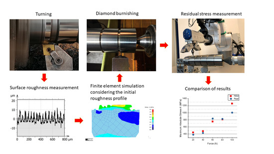
The investigations performed can be divided into two groups: real cutting and burnishing tests and finite element simulations. However, the two were not sharply separated from each other: during the theoretical simulations, the roughness profile measured on the surfaces turned in the workshop was used. In addition, the purpose of the experiments in the workshop was to partially validate the data obtained by simulation.
During the finite element modeling, the real machining processes were approximated as closely as possible within the given boundary conditions. Based on the literature review, it was found that most of the time researchers do not deal with the effect of initial surface roughness during the modeling of burnishing processes, even though plastic deformation of the surface formed in the previous operation takes place during the process. Therefore, the consideration of the real roughness profile was of particular importance during the present investigations. To do this, roughness measurements were performed on the surface obtained during pre-machining (turning) before burnishing, from which a small section (0.4 mm long) was cut out and its points were imported into the finite element software. During the simulation tests, care was taken to leave enough thickness of material under the measured surface profile to be able to examine the impact depth of the compressive force. Figure 1 shows the modeling procedure. This is similar to the three-step iteration procedure introduced by Röttger in [43] and used by many others, e.g., Stöckmann and Putz [44] and Sartkulvanich et al. [20]. This process consists of the following main steps:
- With the given burnishing force, the tool (which was defined as a rigid body during the tests) is pressed into the workpiece for a short period of time (which was appropriately chosen based on the burnishing speed value).
- In the next step, removing the pressure force, the tool is raised above the surface of the workpiece.
- This is followed by moving the tool to the next position with a distance that corresponds to the feed per revolution value.
Although Röttger originally recommended at least four ball impressions for the simulation, recent research [11,20,44] has shown that it is more appropriate to simulate more steps, at least eight. Therefore, eight steps were used in the present research.
The finite element tests were performed in the Deform software from Scientific Forming Technologies Corporation (Columbus, OH, USA). This software is particularly suitable for modeling processes involving plastic deformation, such as diamond burnishing. During the tests, the effect of the burnishing force on the residual stress was primarily examined, and therefore the varied parameter was the burnishing force. The applied technological and simulation parameters are summarized in Table 1. The special parameters required for finite element simulations, such as the number of elements and step time, were determined based on the experience gained from preliminary tests.
The material used during the physical experiments and simulations was EN 1.4301 austenitic stainless steel. Its chemical composition is the following [45]: C ≤ 0.08%; Mn ≤ 2%; 18% ≤ Cr ≤ 20%; Si ≤ 1%; p ≤ 0.045%; S ≤ 0.03%; 8% ≤ Ni ≤ 11%. The mechanical properties of this material grade are the following [46]: yield strength 205–310 MPa; tensile strength 510–620 MPa; Young’s modulus 190–203 GPa; hardness 170–210 HV (75–85 HRB). This material is widely used in industry; its primary uses are architectural applications, pipelines, pressure vessels, valves, heat exchanger tubes and support, food- and dairy-processing equipment, and surgical instruments. Generally, this material can be relatively easily machined and cold formed; additionally, it does not corrode, so it is a good material for conducting burnishing experiments [47]. Furthermore—especially in the previously listed application areas—special requirements on the surface quality and residual stresses are often expected, so the use of burnishing after cutting may be justified there.
The cutting experiments (both the turning and later the burnishing operations) were conducted on an EU 400-01 (Hungary) universal lathe machine. The workpiece was a bar on which five 20 mm shoulders were formed for each force value setting. The applied material grade was identical to the simulation parameters (see Table 1). During the workshop experiments, the surfaces to be tested were first pre-turned. This operation was performed by a CNGA insert with nose radius of 0.8 mm The parameters for the turning process were the following:
- Roughing:
- ○
- cutting speed: vc = 90 m/min;
- ○
- feed: f = 0.1 mm/rev.;
- ○
- depth of cut: ap = 0.25 mm.
- Finishing:
- ○
- cutting speed: vc = 150 m/min;
- ○
- feed: f = 0.05 mm/rev.;
- ○
- depth of cut: ap = 0.05 mm.
The roughness of the turned surfaces was measured using an Altimet (Thonon-les-Bains, France) AltiSurf 520 surface roughness measuring device. During this, a CL2-type confocal chromatic measuring head was used, with an MG140 magnifier. The measurement range of this setup is 300 µm, while the theoretical resolution is up to 0.5 nm. The Altimap (re-branded version of MountainsMap, Besançon, France) software was applied to display the roughness profile and to extract its points for the FEM simulation. In the Deform software, the points can be inserted directly from the text file containing the coordinates of the profile points. In addition to the roughness tests, residual stress measurements were also performed on the turned surfaces to determine the initial stress state.
After the FEM simulations were finished, the real burnishing tests were conducted. The applied burnishing tool diamond tip has a radius of 3.5 mm (identical to the FEM simulations). This burnishing tool was attached to a self-made burnishing device. A mechanical spring with an adjustment screw in this burnishing device ensured the correct preload, according to the force values in Table 1. The characteristics of the spring were recorded in advance with the help of a Kistler force measuring device, so the applied force values can be considered within a standard deviation of about 10% compared to the setup data. The other burnishing parameters were also identical to the simulation values (see Table 1). SAE 10W40 oil was used for lubrication.
Figure 2 shows a snapshot of the burnishing process. Here the working part of the used tool can be seen, as can the workpiece, which was held in a chuck on one side and supported by a rotating center on the other side.
Residual stress of machined and burnished surfaces was measured using a Stresstech Xstress 3000 G3R (Jyväskylä, Finland) diffractometer (see Figure 3), with an MnKα X-ray tube; the tilting angle was +/− 45°, while the number of tilts was 5/5.
3. Results
Among the evaluations, the first thing to mention is the significant improvement in surface roughness as a result of burnishing. After turning, the average values of the most common surface roughness parameters were Ra ≈ 3 µm and Rz ≈ 16 µm. Since all surfaces were turned with the same parameters, the reported values represent the measurement average of all surfaces, while the individual values are shown in Table 2. As a result of the diamond burnishing, a significant improvement occurred in these parameters, as shown by the measured values in Table 2.
Figure 4 depicts the comparison of the roughness profiles measured on the turned and burnished surfaces for Surface 2 (burnishing force of 40 N). The figure clearly shows how the burnishing tool suppresses the roughness peaks and leaves the roughness valleys almost unchanged.
Figure 5 shows a diagrammatic representation of the roughness values of the turned and burnished surfaces. It can be seen that in the case of the smallest burnishing force (20 N), the improvement is not very significant; the best results were achieved for 80 N, and after that, stagnation or a small increase was experienced. This suggests that, in order to improve the roughness, it is not worth applying any burnishing force greater than 80–100 N in the case of this material quality.
During the evaluation of the simulation results, the configuration shown in Figure 6 was used. Here the position of the workpiece and the tool (rigid body) can be seen at the end of the process; the figure also shows the “region of interest” (ROI) area marked in red, where the development of the stresses was investigated. The intention was to designate an area that characterizes the residual stresses in the burnished surface as an ROI. Due to the limitations of two-dimensional modeling, only axial stresses can be examined, which are denoted by Stress-X in the following.
Figure 7 shows the depth distribution of the residual stress for each burnishing value. Here only the previously defined ROI zones are displayed. It can be seen that as the force increases, both the absolute value of the compressive stress and the impact depth also increase. The burnishing tool will obviously smooth out the roughness peaks; this is where the greatest deformation and the greatest stress occur. This is also why it is worth considering the topography of the initial surface when modeling.
In the next step, the residual stress changes caused by diamond burnishing are compared in the case of the FEM simulation and the real cutting experiments. As mentioned earlier, the residual stress measurements were performed on both the turned and burnished surfaces. Table 3 shows the average of these measured values. The examination of the stress states after the turning operation was carried out during a previous study [48]. During the comparison with simulation results, the absolute difference values are taken as a basis.
A numerical comparison of the absolute mean values of the residual stress obtained by FEM simulation and experimentally measured can be found in Table 4. The absolute values of the measured residual stresses were lower by 50–257 MPa in the cases of 20, 40, and 100 N force values. Furthermore, it can also be noticed that at certain force values, a higher stress was measured compared to the FEM data (namely when 60 and 80 N burnishing forces were applied).
As can be seen in Figure 7 and in Figure 8 as well, the distribution of stresses is not uniform: tensile stress is generated on the surface, which at a certain depth passes into compressive stress (at a depth of about 2 μm), which reaches its maximum absolute value on average at a depth of about 10 μm, and then decreases again. The stress curves shown in Figure 8 were recorded in a specific y-direction line on each ROI diagram shown in Figure 7, where the maximum absolute compressive force is not displayed. This is the reason for the numerical differences between the diagram and the tables, but the course of the stress curves is completely characteristic of the burnishing process; this is demonstrated by the fact that other researchers have obtained these hook-shaped curves in their previous research as well [22].
From the average values of the FEM simulations shown in Figure 7, the maximum compressive residual stress was between −440 MPa (when F = 20 N) and −1260 MPa (when F = 100 N). Since there was no initial stress-relieving heat treatment in the workpiece, according to Zhang et al. [22], the value of the residual stress in the initial workpiece can be between −40 and −60 MPa. This may explain why the measured residual stresses are lower than the values obtained in the case of simulations.
The comparison of the residual stress data obtained by FEM simulation and experimentally measured is shown in Figure 9. This figure shows the maximum absolute values. For 20 N, 40 N, and 100 N burnishing forces, the measured residual stress values are approximately 60–257 MPa lower than the values obtained in the case of simulation, although the situation is reversed (i.e., the measured values are higher) in the cases of 60 N and 80 N, where the stress differences are 83 MPa and 17 MPa, respectively.
In some cases, the FEM modeling gives results very close to the real values, but for example, in the case of a force of 100 N, the difference is more than 200 MPa (this is about a 25% difference). However, in general, the accuracy of 2D modeling is acceptable; the average difference was only 13%.
4. Discussion
In the article, the FEM modeling of diamond burnishing based on the measurement of the roughness of previously turned surfaces is presented. The roughness measurements were performed on both turned and burnished surfaces. It was shown that the diamond burnishing clearly improved the surface roughness: at higher applied burnishing force values (80–100 N), an almost 10-fold improvement was observed in the case of the Ra parameter (it changed from ~16 µm to ~3.5 µm). The Rz parameter improved from ~16 µm to ~3.5 µm, which is about a 5-fold improvement.
The finite element investigations were performed using the roughness profiles measured on the turned surfaces. Based on the results of the simulations, it was established that the residual stress is tensile in the immediate vicinity of the surface and changes to compressive stress at a depth of about 2 µm, reaching its maximum absolute value at about 10 µm (the actual value depends on the applied burnishing force). The values of the maximum compressive stress reached were between 442 and 1260 MPa. These results were compared with the residual stress data measured on diamond burnished surfaces during the experiments. On the basis of the investigations, it can be established that with two-dimensional modeling it is possible to model the diamond burnishing process with a relatively good approximation; the difference between the measured and FEM results for Stress-X was between 2 and 25%, while the average difference was 13%. It should be mentioned that the sliding friction between the tool and the workpiece was ignored during the simulations due to the characteristics of the procedure applied. However, it should be highlighted that there is strong lubrication during the real burnishing process as well: in the actual experiments, SAE 10W40 oil was used to reduce the friction between the tool and the workpiece. Another disadvantage of two-dimensional modeling is that it cannot evaluate tangential stresses. On the other hand, a clear advantage compared to three-dimensional modeling is that the calculation is much faster, and the structure and management of the FEM model are simpler. Based on the results of the tests carried out, it can be concluded that even in two-dimensional simulations it is extremely important to consider the initial surface topography: during the burnishing process, the profile obtained during the previous operation is plastically formed, so the actual forming is concentrated on the roughness peaks. Since the burnishing force is concentrated on a smaller surface area on the rough surface, the surface pressure will actually be higher. The presented figures also show that the residual stress is not of the same magnitude under the roughness peaks and valleys. Since the experiments also proved that increasing the burnishing force has a clear positive effect on the residual stresses in this process, two factors should be considered in order to achieve the required stress state of the surfaces: the right value of the burnishing force and the appropriate choice of the preceding operation resulting in the desired roughness profile. If the previous operation creates a surface that is too rough, then the distribution of stresses remaining in the material after burnishing will be less uniform, which may be unfavorable in terms of service life. The determination of this critical value of roughness is beyond the scope of this study and can be a topic of future research.
Author Contributions
Conceptualization, C.F. and G.V.; methodology, C.F. and G.V.; validation, C.F. and G.V.; investigation, C.F. and G.V.; resources, G.V.; data curation, C.F. and G.V.; writing—original draft preparation, C.F.; writing—review and editing, C.F. and G.V.; visualization, C.F.; supervision, C.F. and G.V.; project administration, G.V.; funding acquisition, G.V. All authors have read and agreed to the published version of the manuscript.
Funding
This research was funded by the National Research, Development and Innovation Fund of Hungary, grant number NKFI-125117.
Data Availability Statement
Data available on request due to restrictions.
Acknowledgments
Project No. NKFI-125117 has been implemented with the support provided by the National Research, Development and Innovation Fund of Hungary, financed under the K_17 funding scheme.
Conflicts of Interest
The authors declare no conflict of interest.
References
- Zubrzycki, J.; Świć, A.; Sobaszek, Ł.; Kovac, J.; Kralikova, R.; Jencik, R.; Smidova, N.; Arapi, S. Improvement of shafts by the deep ball-burnishing technique; Cyber-Physical Systems Technologies as a Kes Factor in the Process of Industry 4.0 and Smart Manufacturing Development. Appl. Comput. Sci. 2021, 17, 84–99. [Google Scholar] [CrossRef]
- Kovács, G. Combination of Lean Value-Oriented Conception and Facility Layout Design for Even More Significant Efficiency Improvement and Cost Reduction. Int. J. Prod. Res. 2020, 58, 2916–2936. [Google Scholar] [CrossRef]
- Kudryavtsev, Y.F. Residual Stress. In Springer Handbook of Experimental Solid Mechanics; Sharpe, W.N., Ed.; Springer Handbooks; Springer US: Boston, MA, USA, 2008; pp. 371–388. ISBN 978-0-387-30877-7. [Google Scholar]
- Alshareef, A.J.; Marinescu, I.D.; Basudan, I.M.; Alqahtani, B.M.; Tharwan, M.Y. Ball-Burnishing Factors Affecting Residual Stress of AISI 8620 Steel. Int. J. Adv. Manuf. Technol. 2020, 107, 1387–1397. [Google Scholar] [CrossRef]
- Lu, J. A Global Design Approach to the Residual Stress Problem. In Handbook of Residual Stress and Deformation of Steel; Totten, G.E., Ed.; ASM International: Materials Park, OH, USA, 2002; pp. 11–26. ISBN 978-1-61503-227-3. [Google Scholar]
- Gubán, M.; Kovács, G. Industry 4.0 Conception. Acta Tech. Corveniensis-Bull. Eng. 2017, 10, 111–114. [Google Scholar]
- Li, F.; Li, X.; Wang, T.; Rong, Y.; Liang, S.Y. In-Process Residual Stresses Regulation during Grinding through Induction Heating with Magnetic Flux Concentrator. Int. J. Mech. Sci. 2020, 172, 105393. [Google Scholar] [CrossRef]
- Mader, S.; Klocke, F. Fundamentals of the Deep Rolling of Compressor Blades for Turbo Aircraft Engines. Steel Res. Int. 2005, 76, 229–235. [Google Scholar] [CrossRef]
- Loh, N.H.; Tam, S.C. Effects of Ball Burnishing Parameters on Surface Finish—A Literature Survey and Discussion. Precis. Eng. 1988, 10, 215–220. [Google Scholar] [CrossRef]
- Alshareef, A.M. Investigation and Modeling of Ball-Burnishing Factors Affecting Residual Stress of AISI 8620 Steel; University of Toledo: Toledo, OH, USA, 2020. [Google Scholar]
- Rodríguez, A.; López de Lacalle, L.N.; Celaya, A.; Lamikiz, A.; Albizuri, J. Surface Improvement of Shafts by the Deep Ball-Burnishing Technique. Surf. Coat. Technol. 2012, 206, 2817–2824. [Google Scholar] [CrossRef]
- Jerez-Mesa, R.; Fargas, G.; Roa, J.J.; Llumà, J.; Travieso-Rodriguez, J.A. Superficial Effects of Ball Burnishing on TRIP Steel AISI 301LN Sheets. Metals 2021, 11, 82. [Google Scholar] [CrossRef]
- Fernández-Osete, I.; Estevez-Urra, A.; Velázquez-Corral, E.; Valentin, D.; Llumà, J.; Jerez-Mesa, R.; Travieso-Rodriguez, J.A. Ultrasonic Vibration-Assisted Ball Burnishing Tool for a Lathe Characterized by Acoustic Emission and Vibratory Measurements. Materials 2021, 14, 5746. [Google Scholar] [CrossRef]
- López de Lacalle, L.N.; Rodríguez, A.; Lamikiz, A.; Celaya, A.; Alberdi, R. Five-Axis Machining and Burnishing of Complex Parts for the Improvement of Surface Roughness. Mater. Manuf. Process. 2011, 26, 997–1003. [Google Scholar] [CrossRef]
- Sánchez Egea, A.J.; Rodríguez, A.; Celentano, D.; Calleja, A.; López de Lacalle, L.N. Joining Metrics Enhancement when Combining FSW and Ball-Burnishing in a 2050 Aluminium Alloy. Surf. Coat. Technol. 2019, 367, 327–335. [Google Scholar] [CrossRef] [Green Version]
- Rodríguez, A.; Calleja, A.; López de Lacalle, L.; Pereira, O.; González, H.; Urbikain, G.; Laye, J. Burnishing of FSW Aluminum Al–Cu–Li Components. Metals 2019, 9, 260. [Google Scholar] [CrossRef] [Green Version]
- Plaza, E.I.; Marcaide, L.N.L.D.L.C.; Ezquerro, A.R.; Oscoz, M.P.; Gil, A.; Edesa, M.O. Improvement of the Surface Quality of Incrementally Formed Parts by Means of Hydrostatic Ball Burnishing. DYNA 2018, 93, 650–655. [Google Scholar] [CrossRef]
- Avilés, R.; Albizuri, J.; Rodríguez, A.; López de Lacalle, L.N. Influence of Low-Plasticity Ball Burnishing on the High-Cycle Fatigue Strength of Medium Carbon AISI 1045 Steel. Int. J. Fatigue 2013, 55, 230–244. [Google Scholar] [CrossRef]
- Avilés, A.; Avilés, R.; Albizuri, J.; Pallarés-Santasmartas, L.; Rodríguez, A. Effect of Shot-Peening and Low-Plasticity Burnishing on the High-Cycle Fatigue Strength of DIN 34CrNiMo6 Alloy Steel. Int. J. Fatigue 2019, 119, 338–354. [Google Scholar] [CrossRef]
- Sartkulvanich, P.; Altan, T.; Jasso, F.; Rodriguez, C. Finite Element Modeling of Hard Roller Burnishing: An Analysis on the Effects of Process Parameters Upon Surface Finish and Residual Stresses. J. Manuf. Sci. Eng. 2007, 129, 705–716. [Google Scholar] [CrossRef]
- Rodríguez, A.; López de Lacalle, L.N.; Fernández, A.; Braun, S. Elimination of Surface Spiral Pattern on Brake Discs. J. Zhejiang Univ. Sci. A 2014, 15, 53–60. [Google Scholar] [CrossRef] [Green Version]
- Zhang, D.; Zhang, X.-M.; Ding, H. Experimental and Numerical Study of the Subsurface Deformation and Residual Stress during the Roller Burnishing Process. Procedia CIRP 2020, 87, 491–496. [Google Scholar] [CrossRef]
- Xu, X.; Liu, D.; Zhang, X.; Liu, C.; Liu, D.; Zhang, W. Influence of Ultrasonic Rolling on Surface Integrity and Corrosion Fatigue Behavior of 7B50-T7751 Aluminum Alloy. Int. J. Fatigue 2019, 125, 237–248. [Google Scholar] [CrossRef]
- El-Khabeery, M.M.; El-Axir, M.H. Experimental Techniques for Studying the Effects of Milling Roller-Burnishing Parameters on Surface Integrity. Int. J. Mach. Tools Manuf. 2001, 41, 1705–1719. [Google Scholar] [CrossRef]
- Yuan, X.L.; Sun, Y.W.; Gao, L.S.; Jiang, S.L. Effect of Roller Burnishing Process Parameters on the Surface Roughness and Microhardness for TA2 Alloy. Int. J. Adv. Manuf. Technol. 2016, 85, 1373–1383. [Google Scholar] [CrossRef]
- Yuan, X.; Sun, Y.; Li, C.; Liu, W. Experimental Investigation into the Effect of Low Plasticity Burnishing Parameters on the Surface Integrity of TA2. Int. J. Adv. Manuf. Technol. 2017, 88, 1089–1099. [Google Scholar] [CrossRef]
- Wang, Y.; Li, Y.; Sun, K. Effect of Process Duration on the Microstructures of Fast Multiple Rotation Rolling-Induced Nanocrystalline Layer and Its Wear Properties. J. Mater. Process. Technol. 2018, 252, 159–166. [Google Scholar] [CrossRef]
- Zhang, T.; Bugtai, N.; Marinescu, I.D. Burnishing of Aerospace Alloy: A Theoretical–Experimental Approach. J. Manuf. Syst. 2015, 37, 472–478. [Google Scholar] [CrossRef]
- Hua, Y.; Liu, Z.; Wang, B.; Jiang, J. Residual Stress Regenerated on Low Plasticity Burnished Inconel 718 Surface after Initial Turning Process. J. Manuf. Sci. Eng. 2019, 141, 121004. [Google Scholar] [CrossRef]
- Yen, Y.C.; Sartkulvanich, P.; Altan, T. Finite Element Modeling of Roller Burnishing Process. CIRP Ann. 2005, 54, 237–240. [Google Scholar] [CrossRef]
- Rodriguez, A.; de Lacalle, L.N.L.; Pereira, O.; Fernandez, A.; Ayesta, I. Isotropic Finishing of Austempered Iron Casting Cylindrical Parts by Roller Burnishing. Int. J. Adv. Manuf. Technol. 2020, 110, 753–761. [Google Scholar] [CrossRef]
- Sachin, B.; Narendranath, S.; Chakradhar, D. Effect of Cryogenic Diamond Burnishing on Residual Stress and Microhardness of 17-4 PH Stainless Steel. Mater. Today Proc. 2018, 5, 18393–18399. [Google Scholar] [CrossRef]
- Sachin, B.; Rao, C.M.; Naik, G.M.; Durga Prasad, C.; Hebbale, A.M.; Vijeesh, V.; Rao, M. Minimum Quantity Lubrication and Cryogenic for Burnishing of Difficult to Cut Material as a Sustainable Alternative. In Sustainable Machining Strategies for Better Performance; Srinivasa Pai, P., Krishnaraj, V., Eds.; Lecture Notes in Mechanical Engineering; Springer: Singapore, 2022; pp. 61–69. ISBN 9789811622786. [Google Scholar]
- Zielecki, W.; Bucior, M.; Trzepiecinski, T.; Ochał, K. Effect of Slide Burnishing of Shoulder Fillets on the Fatigue Strength of X19NiCrMo4 Steel Shafts. Int. J. Adv. Manuf. Technol. 2020, 106, 2583–2593. [Google Scholar] [CrossRef]
- Teimouri, R. Optimization of Residual Stress Field in Ultrasonic Assisted Burnishing Process. Int. J. Lightweight Mater. Manuf. 2019, 2, 346–354. [Google Scholar] [CrossRef]
- Korzynski, M.; Pacana, A.; Cwanek, J. Fatigue Strength of Chromium Coated Elements and Possibility of Its Improvement with Slide Diamond Burnishing. Surf. Coat. Technol. 2009, 203, 1670–1676. [Google Scholar] [CrossRef]
- Hamadache, H.; Bourebia, M.; Taamallah, O.; Laouar, L. Surface Hardening of 36 NiCrMo 6 Steel by Ball Burnishing Process. Mater. Res. Express 2019, 6, 106538. [Google Scholar] [CrossRef]
- Okada, M.; Terada, S.; Shinya, M.; Sasaki, T.; Kataoka, Y.; Kihara, T.; Miura, T.; Otsu, M. Surface Finishing and Enhancement of Ni-Based Alloy Using Sliding Burnishing with Active Rotary Tool. Int. J. Adv. Manuf. Technol. 2020, 107, 4661–4676. [Google Scholar] [CrossRef]
- Varga, G.; Ferencsik, V. Examination of Residual Stresses on Diamond Burnished Cylindrical Surfaces. Rezan. Instrum. V Tehnol. Sist. 2017, 87, 18–27. [Google Scholar]
- Maximov, J.T.; Anchev, A.P.; Duncheva, G.V.; Ganev, N.; Selimov, K.F. Influence of the Process Parameters on the Surface Roughness, Micro-Hardness, and Residual Stresses in Slide Burnishing of High-Strength Aluminum Alloys. J. Braz. Soc. Mech. Sci. Eng. 2017, 39, 3067–3078. [Google Scholar] [CrossRef]
- Maximov, J.T.; Duncheva, G.V.; Anchev, A.P.; Ichkova, M.D. Slide Burnishing—Review and Prospects. Int. J. Adv. Manuf. Technol. 2019, 104, 785–801. [Google Scholar] [CrossRef]
- Maximov, J.T.; Duncheva, G.V.; Anchev, A.P.; Dunchev, V.P.; Ichkova, M.D. Improvement in Fatigue Strength of 41Cr4 Steel through Slide Diamond Burnishing. J. Braz. Soc. Mech. Sci. Eng. 2020, 42, 197. [Google Scholar] [CrossRef]
- Röttger, K. Walzen Hartgedrehter Oberflächen; Berichte aus der Produktionstechnik; Shaker: Aachen, Germany, 2003; ISBN 978-3-8322-1177-6. [Google Scholar]
- Stöckmann, R.; Putz, M. Modelling of Surface Formation Mechanism during Burnishing of Aluminium. Procedia CIRP 2019, 82, 450–454. [Google Scholar] [CrossRef]
- Ahmed, Y.S.; Fox-Rabinovich, G.; Paiva, J.M.; Wagg, T.; Veldhuis, S.C. Effect of Built-up Edge Formation during Stable State of Wear in AISI 304 Stainless Steel on Machining Performance and Surface Integrity of the Machined Part. Materials 2017, 10, 1230. [Google Scholar] [CrossRef]
- Strzelecki, P.; Mazurkiewicz, A.; Musiał, J.; Tomaszewski, T.; Słomion, M. Fatigue Life for Different Stress Concentration Factors for Stainless Steel 1.4301. Materials 2019, 12, 3677. [Google Scholar] [CrossRef] [PubMed] [Green Version]
- Ahmed, Y.S.; Youssef, H.; El-Hofy, H.; Ahmed, M. Prediction and Optimization of Drilling Parameters in Drilling of AISI 304 and AISI 2205 Steels with PVD Monolayer and Multilayer Coated Drills. J. Manuf. Mater. Process. 2018, 2, 16. [Google Scholar] [CrossRef]
- Zaghal, J.; Mertinger, V.; Filep, A.; Varga, G.; Benke, M. Characterization of Residual Stresses Induced into Bearing Rings by Means of Turning in Soft State Using Different Turning Parameters. J. Mach. Eng. 2021, 21, 49–56. [Google Scholar] [CrossRef]
Figure 1.
Three steps from the applied modeling method.

Figure 2.
Burnishing experiment.

Figure 3.
Residual stress measurement using a Stresstech Xstress 3000 G3R diffractometer.

Figure 4.
Roughness profiles after turning and after burnishing for Surface 2 (F = 40 N).

Figure 5.
Comparison of the common roughness parameters for the turned and burnished surfaces.

Figure 6.
The position of the tool at the end of the process and the ROI for investigations.

Figure 7.
ROI areas with Stress-X coloring for the different applied burnishing force values.

Figure 8.
Depth distribution of the axial stress value (Stress-X).

Figure 9.
Comparison of the maximum absolute compressive stress values obtained by finite element modeling and measurements.
Figure 9.
Comparison of the maximum absolute compressive stress values obtained by finite element modeling and measurements.


Table 1.
The burnishing parameters applied in FEM simulations.
| Parameter Type | Parameter | Value(s) |
|---|---|---|
| Technological parameters | Burnishing force | 20, 40, 60, 80, 100 N |
| Feed | 0.0125 mm/rev. | |
| Spindle speed | 375 RPM | |
| Simulation parameters | Workpiece mesh | 6844 elements, 7149 nodes |
| Material | EN 1.4301 austenitic stainless steel (DINX5CrNi1810) | |
| Tool | Rigid body, R = 3.5 mm | |
| Friction coefficient | 0.08 | |
| Step time | 0.01 s | |
| No. of steps | 8 |
Table 2.
Measured roughness parameters after turning and after burnishing.
| Surface | Burnishing Force (N) | Ra (µm) | Rz (µm) | ||
|---|---|---|---|---|---|
| after Turning | after Burnishing | after Turning | after Burnishing | ||
| 1 | 20 | 2.63 | 2.51 | 16 | 12.6 |
| 2 | 40 | 3.34 | 0.997 | 18.7 | 9.34 |
| 3 | 60 | 2.88 | 0.407 | 15.8 | 3.8 |
| 4 | 80 | 3.01 | 0.338 | 15.6 | 3.35 |
| 5 | 100 | 3.1 | 0.34 | 15.5 | 3.73 |
Table 3.
Measured residual stress values after turning and burnishing.
| Force (N) | Stress-X (MPa) | ||
|---|---|---|---|
| after Turning | after Burnishing | Absolute Difference | |
| 20 | −247.2 | −628.9 | 381.7 |
| 40 | −318.45 | −748.5 | 430.05 |
| 60 | −274.57 | −1110.53 | 835.97 |
| 80 | −287.6 | −1113.9 | 826.3 |
| 100 | −135.45 | −1138.35 | 1002.9 |
Table 4.
Simulated and measured residual stress change due to burnishing.
| Force (N) | Maximum Absolute Stress-X (MPa) | |
|---|---|---|
| FEM | Measured (Approx.) | |
| 20 | 442 | 382 |
| 40 | 480 | 430 |
| 60 | 753 | 836 |
| 80 | 809 | 826 |
| 100 | 1260 | 1003 |
Publisher’s Note: MDPI stays neutral with regard to jurisdictional claims in published maps and institutional affiliations. |
© 2022 by the authors. Licensee MDPI, Basel, Switzerland. This article is an open access article distributed under the terms and conditions of the Creative Commons Attribution (CC BY) license (https://creativecommons.org/licenses/by/4.0/).
Share and Cite
MDPI and ACS Style
Felhő, C.; Varga, G. 2D FEM Investigation of Residual Stress in Diamond Burnishing. J. Manuf. Mater. Process. 2022, 6, 123. https://doi.org/10.3390/jmmp6050123
AMA Style
Felhő C, Varga G. 2D FEM Investigation of Residual Stress in Diamond Burnishing. Journal of Manufacturing and Materials Processing. 2022; 6(5):123. https://doi.org/10.3390/jmmp6050123
Chicago/Turabian StyleFelhő, Csaba, and Gyula Varga. 2022. "2D FEM Investigation of Residual Stress in Diamond Burnishing" Journal of Manufacturing and Materials Processing 6, no. 5: 123. https://doi.org/10.3390/jmmp6050123