


Abstract
Poly-crystalline diamond (PCD) is an extremely tough, synthetically produced cutting tool material, which offers outstanding capabilities concerning wear behavior in abrasive cutting environments. Currently, the primary application of PCD cutting tools is the machining of non-ferrous materials, as the diamond’s carbon high affinity towards iron causes diffusion effects while cutting steel with rising temperature. This effect significantly reduces tool life. To lower the occurring temperature of the cutting process, and therefore avoid the reaction of carbon and iron, a thermal functionalization of the cutting inserts has been investigated. The results give insight into making PCD cutting tools economically usable for the machining of iron-carbon materials.
1. Introduction
Diamond is the material with the highest known hardness, and has outstanding characteristics concerning its thermal conductivity, young’s modulus and compressive strength [1]. Poly-crystalline diamond is produced by sintering of selected diamond particles under high pressure and at a high temperature, and is almost exclusively used for economic cutting of non-ferrous materials in the field of production engineering. According to the literature, it is not recommended to apply PCD for the machining of iron-carbon alloys due to its high chemical affinity to ferrous materials and its thermal instability beyond approx. 700 °C, with graphitization and critical tool wear as a drastic consequence [2]. For the cutting of light metals, the process temperatures are below this critical temperature threshold, so these materials can be machined with PCD cutting tools in a sustainable way. As the cutting tool’s temperature may be decreased by proper process cooling, economically viable machining of iron-carbon alloys with PCD cutting inserts could be achieved; this may be similarly shown while machining cast iron using cryogenic cooling in References [3,4,5]. In the present work, PCD cutting inserts are modified with an internal cooling channel in the tungsten carbide substrate below the PCD-blank, to lower the occurring temperatures during cutting and assure the efficient machining of cast iron.
2. Internal Cooling
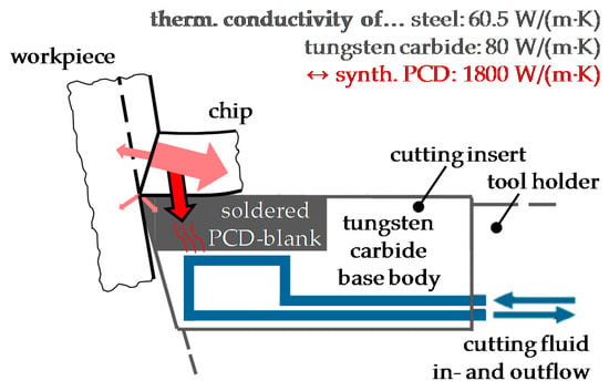
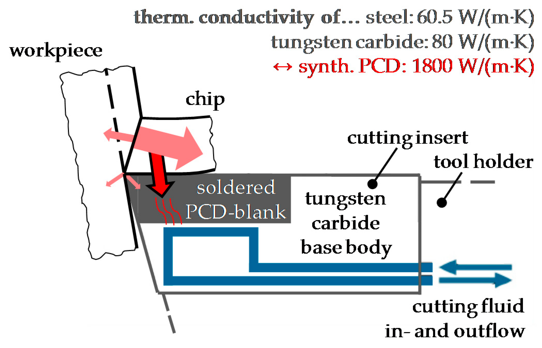
As previous investigations on the additional internal cooling of cutting inserts showed promising results [6,7], similar modification was chosen to be applied for PCD inserts (insert code: TCMW 16T312; cemented tungsten carbide base body with PCD-blank—thickness of 480 µm—alongside one cutting edge, edge radius of approx. 12 µm). A flow optimized cooling channel was processed by electric-discharge machining (EDM) into the cutting insert’s base body at an adequate distance beneath the PCD-blank to avoid damage of the joint interface between tungsten carbide and PCD (see schematic illustration in Figure 1). The geometry of the internal cooling channel has been designed considering the results of Finite Elements Method (FEM) simulations, which were used to optimize the size and position of the channel and to carry out comprehensive calculations concerning stiffness and stress due to the force load (cf. [6,7]).
Figure 1.
Schematic illustration of cutting process with internally cooled PCD cutting insert and indicated transmission of resulting process heat (red arrows).
3. Model-Based Analysis
3.1. Analytical Calculation of the Thermal Energy
For calculating the cutting force, the Kienzle-equation (with correction factors) can be applied as a standard (Equation (1)):
With the chosen parameters b = 1.262 mm, h = 0.067 mm, κ = 72° (tool cutting edge angle), mc (cast iron) = 0.170, kc1.1 (cast iron) = 1480 MPa, Kv (vc > 100) = 0.959, Kγ (γ0 = 2°) = 1.02, Ksch (ceramics/CBN) = 0.9, Kver (sharp) = 1 (see also Table 1), the cutting force for the used nodular cast iron EN-GJS-600-3 (EN-JS1060) is calculated with 173.6 N. By the use of this result, the average thermal energy for the chip section can be calculated by Equation (2) with 104.1 W. This result can be achieved by the assumption, that due to the excellent thermal conductivity of diamond an average value of 20% was chosen for the resulting heat absorbed by the tool (compared to 18% for the machining of steel with a carbide cutting tool [1]; see also material properties in Table 2):
Table 1.
Process parameters for cutting tests.
Table 2.
Simulation parameters.
3.2. FEM-Simulations
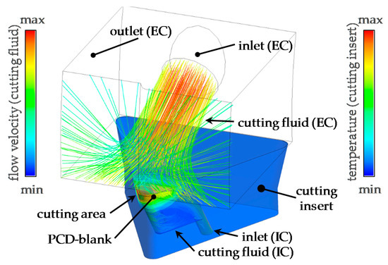
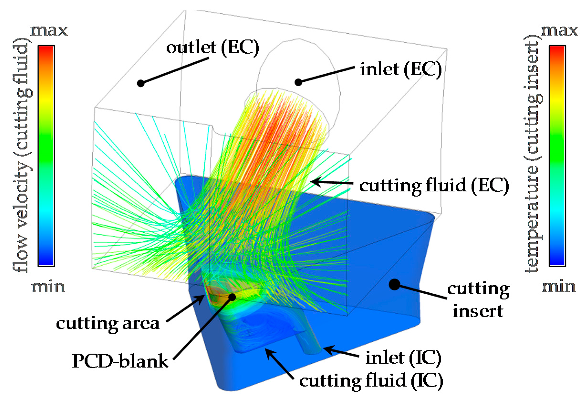
With the result for the average thermal energy and the CAD-model of the cutting insert with an ED-machined cooling channel, a two-way-coupled fluid-structure analysis (FSI) was investigated using the software ANSYS WB. In this simulation, ANSYS CFX-transient and thermic-transient were linked numerically. For the cross section of the cutting edge, the calculated 104.1 W for the average thermal energy and 1.5 W/m2 for the air convection around the cutting insert were applied. The further thermic parameters arise out of the FSI-simulation with water as the inserted default cutting fluid (initial cutting fluid temperature 20 °C). The applied simulation setup is depicted in Figure 2; Table 2 shows the parameters applied for the FSI-simulation.
Figure 2.
Simulation setup for various cooling strategies.
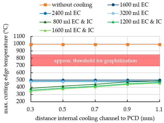
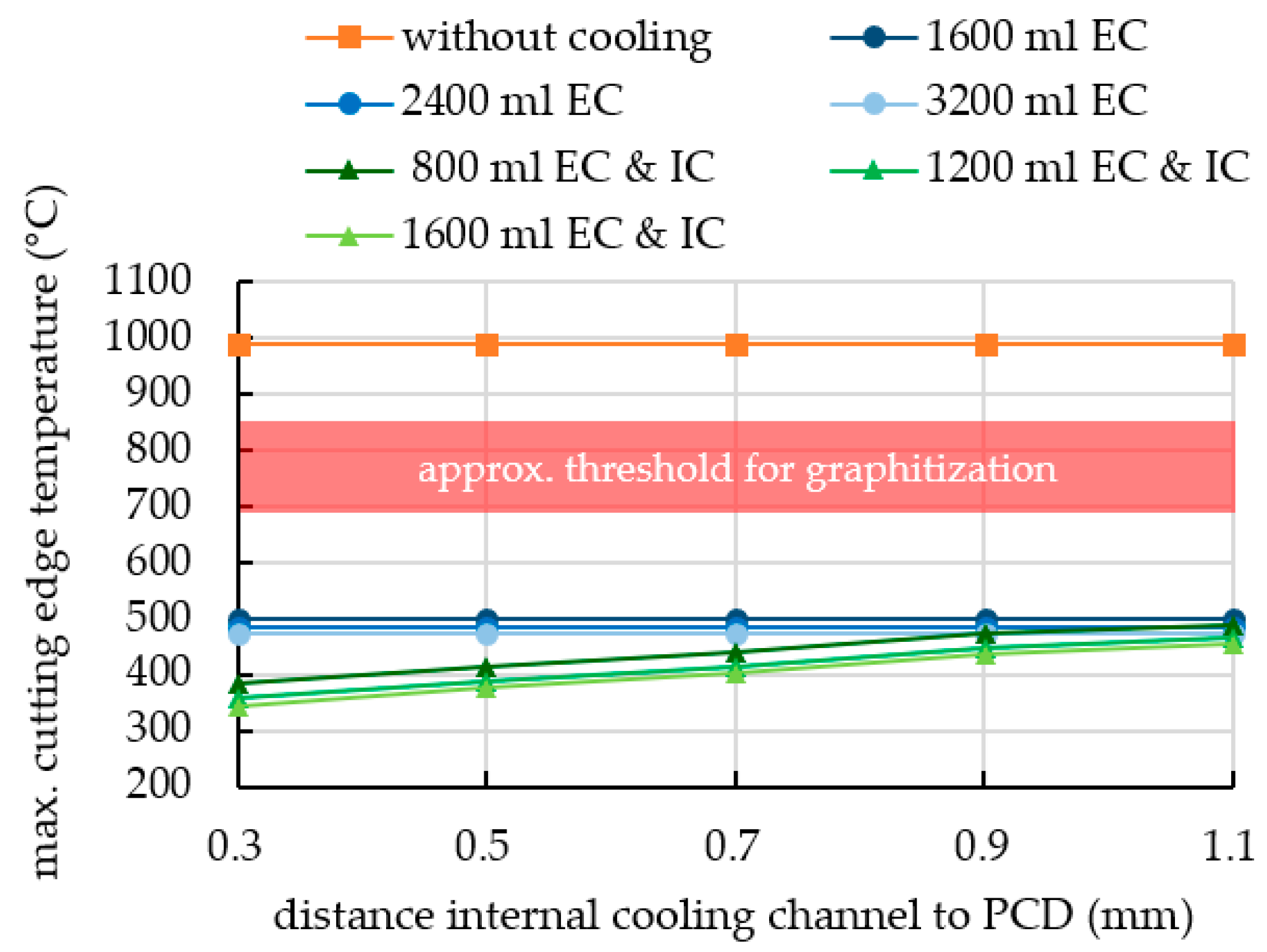
The chart in Figure 3 represents the FSI-simulation results for the maximum cutting-edge temperature as a function of the distance from the internal cooling (IC) channel to the PCD-blank. Without any type of cooling, the temperature in the cutting area rises up to 980 °C (regarding a machining time interval of 1 s). With solely external high-pressure cooling (EC), the temperature can already be reduced below 500 °C for a flow rate of 800 mL/min, and further to a minimum of 473 °C by increasing the flow rate to 1600 mL/min. Simultaneous internal and external cooling reduces the maximum temperature on the cutting edge considerably to values below 500 °C.
Figure 3.
FSI-Simulation results.
A decreasing distance of the cooling channel to the PCD-blank (and therefore to the cutting edge/area) reduces the occurring temperatures in an adequate way and prevents, in combination with external high-pressure cooling, temperatures higher than the critical value. This effect may be useful for further investigations, e.g., minimum quantity lubrication as external cooling in particular with respect to lower distances of the internal cooling channel to the PCD-blank. This could reduce the amount of cutting fluid as well as wear on the rake and flank face due to the tribochemical characteristics of the applied lubricant.
4. Experimental Cutting Tests
4.1. Initial Cutting Tests
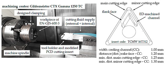
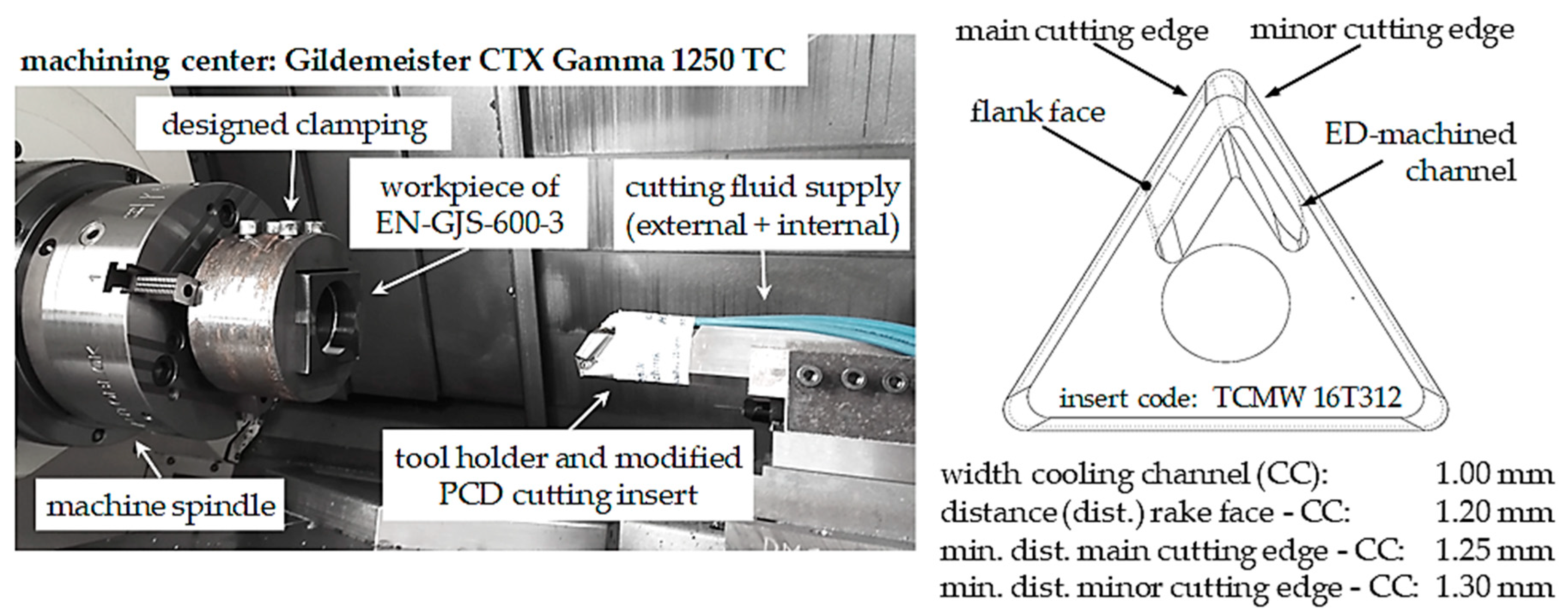
As the theoretical investigations showed promising results to achieve proper process cooling of the PCD cutting tool, initial tests on a turning lathe were carried out. A specifically designed tool holder was adapted with additional holes for inlet and outlet to enable an internal cooling of the cutting insert. Another outlet channel was used for supplying additional fluid for the external cooling of the cutting process. After mounting the adapted cutting insert on the tool holder, the contact surfaces were sealed with a two-component adhesive to avoid leakage (comparable to former investigations in Reference [7]). The herein shown proof of concept cutting tests were performed with a cooling channel that lies at the closest area 1.2 mm beneath the rake face surface (0.7 mm beneath the PCD-blank), resulting in a minimum distance of 1.25 mm between the cooling channel and the main cutting edge. The applied process parameters for the initial cutting tests are shown in Table 1. The internal cooling flow rate of 1600 mL/min was chosen based on the maximum possible value of the used machining center and cutting tool configuration. Precision boring (or in this specific case precision turning) was examined from a diameter of 60 mm up to 67.2 mm in three steps. The experimental tests were performed on a Gildemeister CTX Gamma 1250 TC with an already existing workpiece configuration of preceding research works [8], shown in Figure 4. The workpieces are made of EN-GJS-600-3 as already applied for the theoretical calculations.
Figure 4.
Experimental setup for initial cutting tests (left) and bottom view of CAD-model of applied, internally cooled cutting insert with characteristic measurements (right).
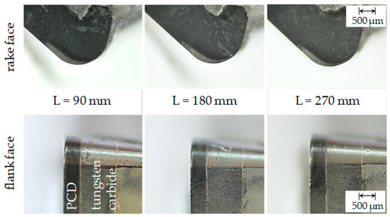
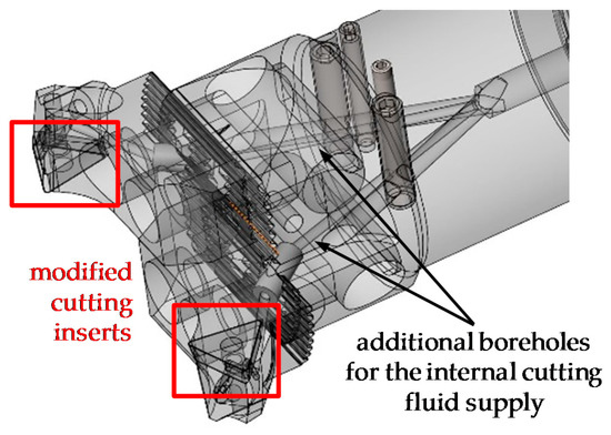
After each cutting length of 90 mm, the tool was dismantled and the tool wear was documented. The wear pattern on the rake and flank face were evaluated qualitatively, as shown in Figure 5. Subsequently, the tool was reinstalled in the machining center and machining was continued. The combination of external and internal cooling was used for the adequate cooling of the tool while machining. As a result, this type of cooling of the PCD cutting insert allowed an economical way of machining iron-carbon alloys. However, this type of modified cutting tool showed no abnormal or exceptional wear patterns.
Figure 5.
Results of wear pattern at the PCD cutting insert’s rake (top) and flank face (bottom) after each 90 mm machining length.
4.2. Series-Production Related Cutting Tests
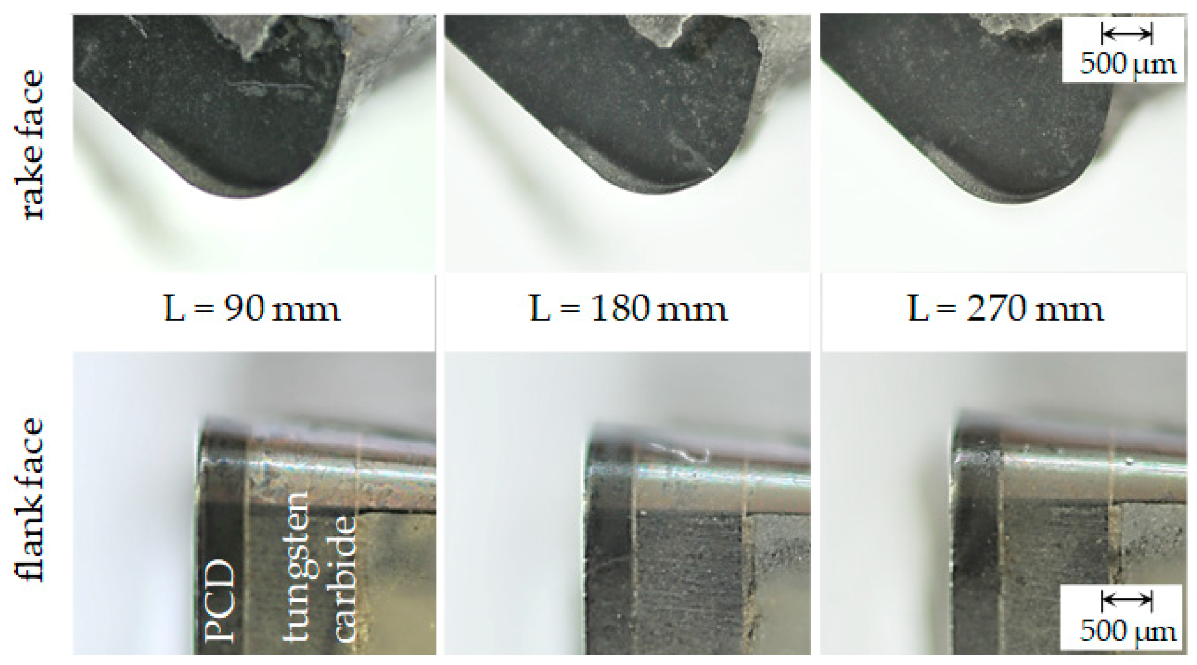
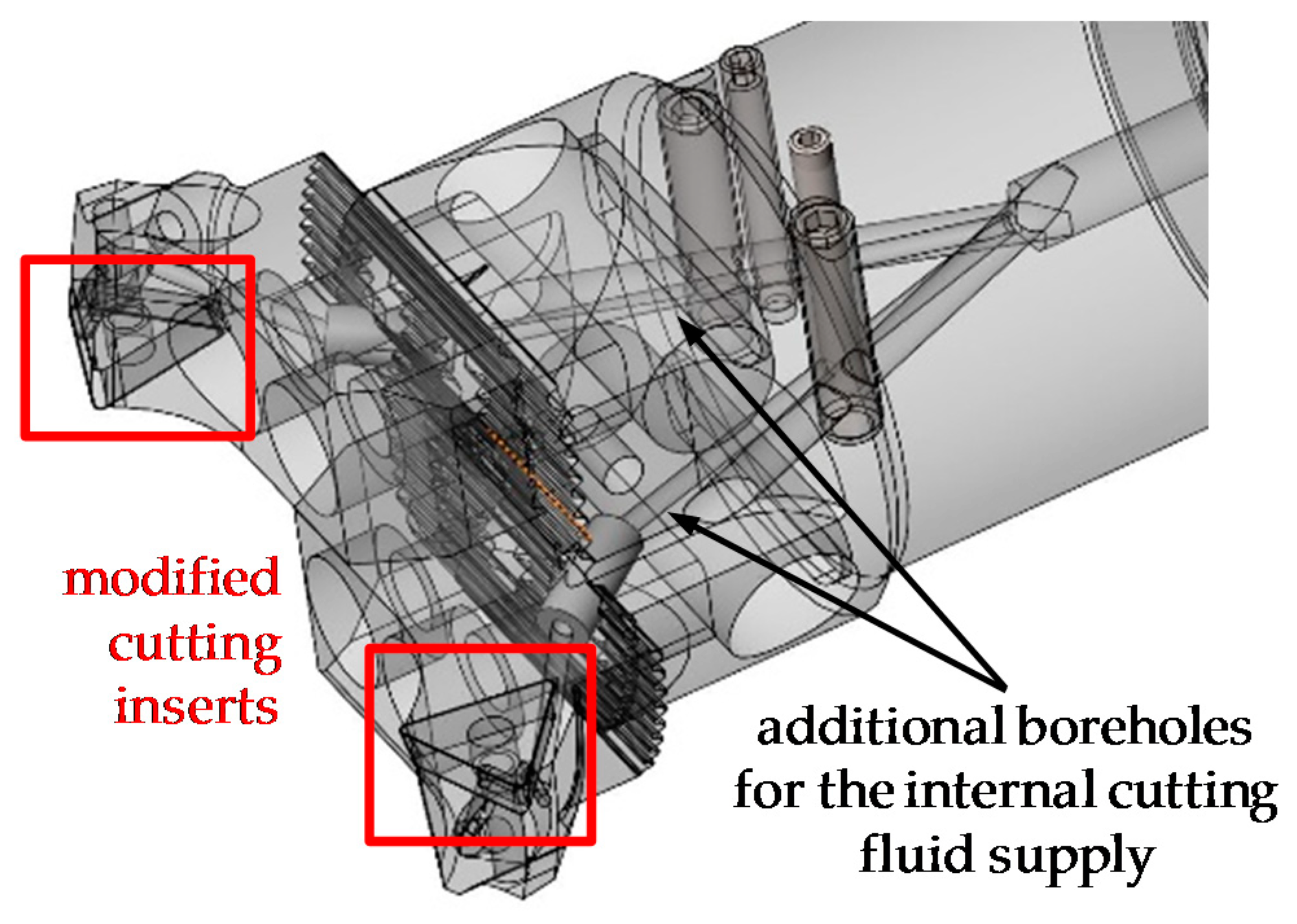
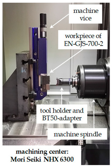
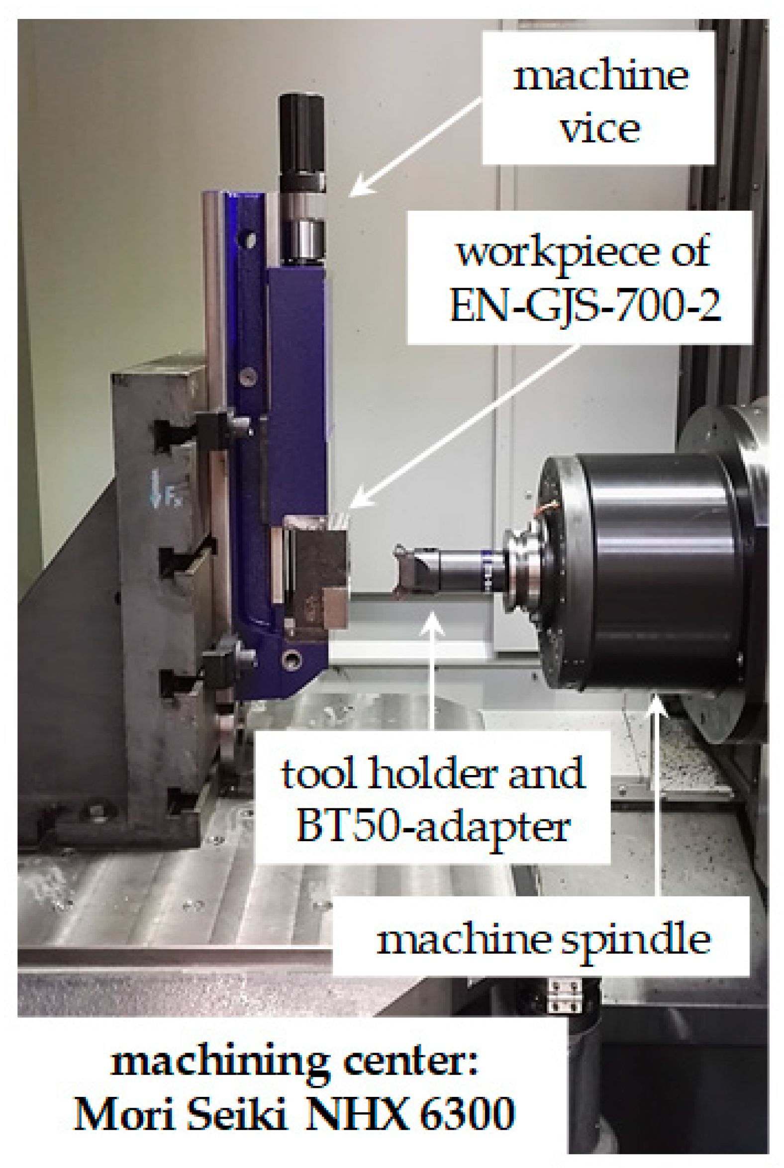
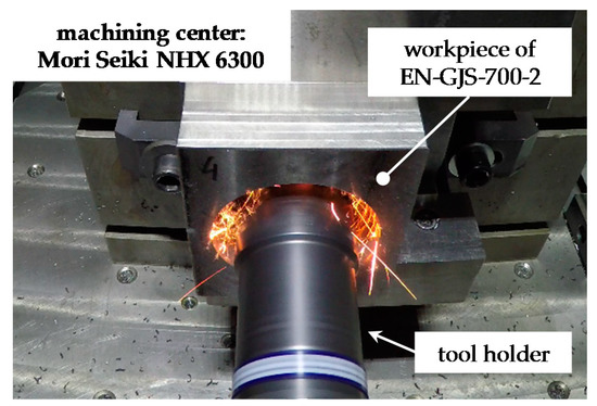
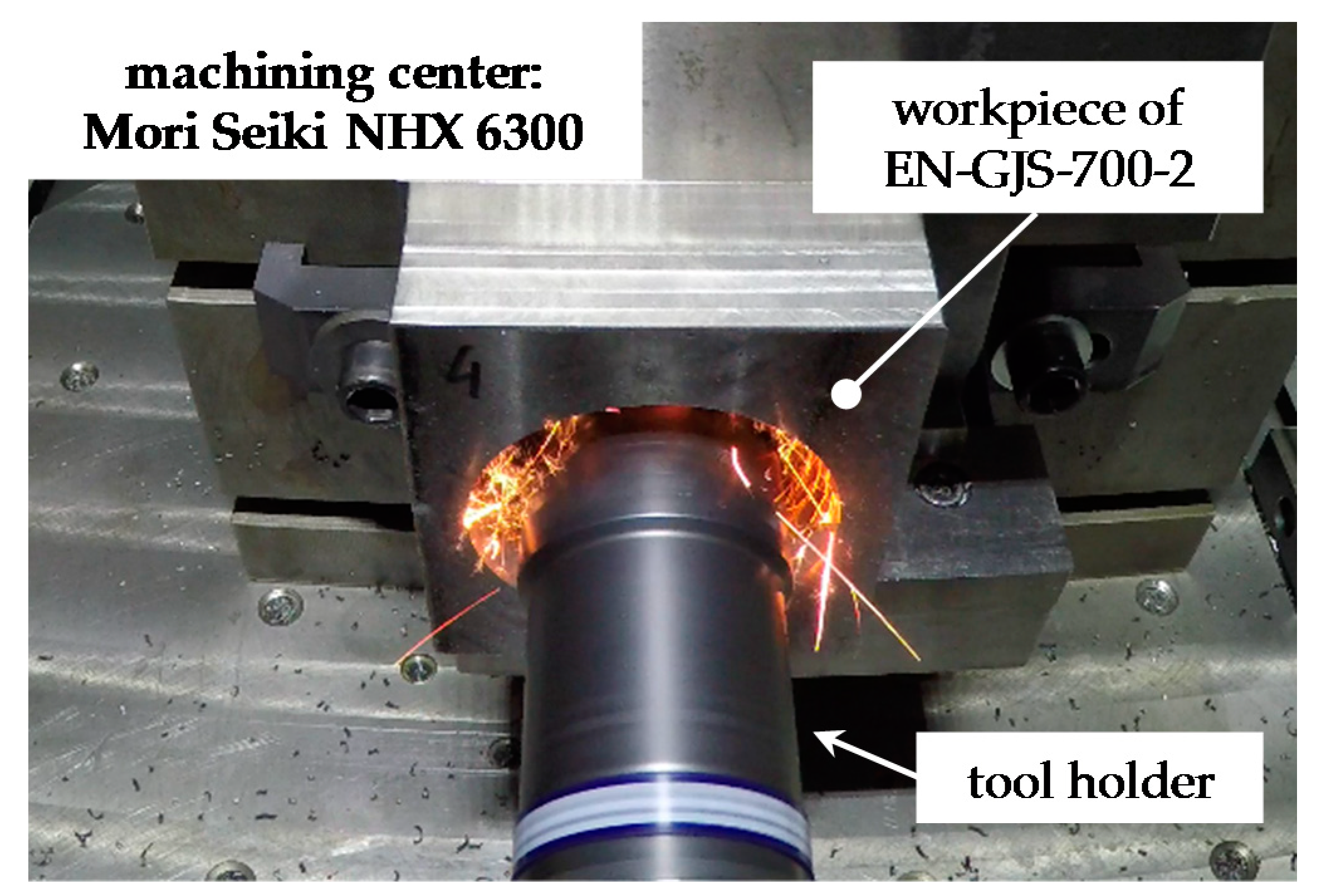
In order to extend the cutting experiments, a conventional boring tool holder was adapted with additional holes for internal cooling of the cutting insert (see Figure 6). The cooling channel geometry and the distance to the rake face were chosen similarly as for the initial tests. Again, the contact surfaces between modified cutting insert and tool holder were sealed with a two-component adhesive to avoid leakage. By the use of this tool holder, a series production-related arrangement in the Mori Seiki NHX 6300 machining center was assembled, as depicted in Figure 7. Although the tool holder can be equipped with two cutting inserts, only one of them was used for the cutting tests out of financial/economic reasons. The applied process parameters for the cutting tests are again listed in Table 1. Moreover, the workpieces for the extension of the cutting tests were made of EN-GJS-700-2 (EN-JS1070).
Figure 6.
Adaption of tool holder for internal cooling.
Figure 7.
Setup for series-production related cutting tests.
For comparison reasons, a dry machining using a conventional, cemented tungsten carbide cutting insert with TiAlN-coating (insert code: TCMW 16T308) was performed—representing the standard process for the cutting of cast iron material. The compared PCD cutting insert represented as-delivered condition. After a few seconds of machining, the diamond material of this cutting insert reacted with the machined cast iron and massive tool wear by graphitization took place initially. The PCD cutting insert’s cutting edge was damaged (see Figure 8), whereas the dry cutting process with the conventional coated tungsten carbide insert did not cause any severe tool wear problems. Following, three different cooling strategies for the (modified) PCD cutting inserts were performed: First, solely external flood cooling was applied (cutting fluid flow rate of 22 L/min). Second, internal cooling was examined almost exclusively, as the marginal external volume flow of cutting fluid derived from the outlet of the internal cooling channel that guides the fluid out of the tool holder towards feed direction. Internal cutting fluid flow rate was 1200 mL/min, as the coolant pump pressure had to be lowered due to leak resistance. Third, the combination of external and internal cooling has been tested for the sake of completeness (with an internal cutting fluid flow rate of 2200 mL/min).
Figure 8.
Drastic wear effects due to dry machining with a PCD cutting insert.
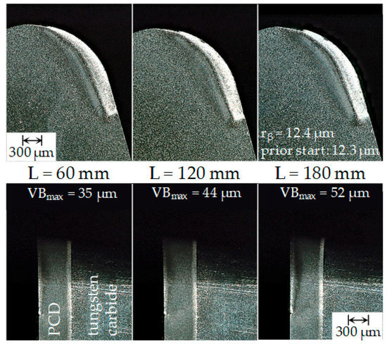
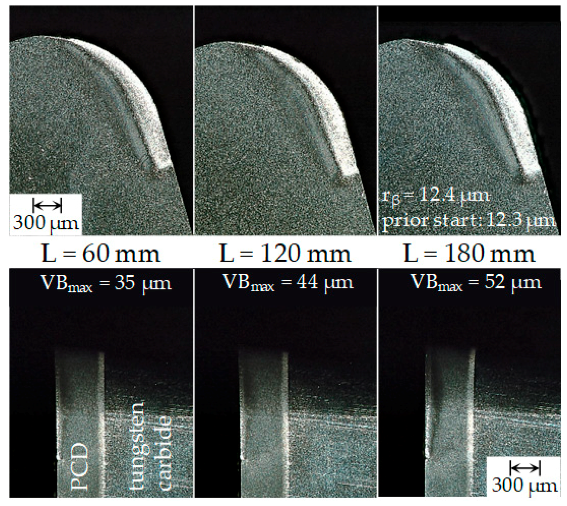
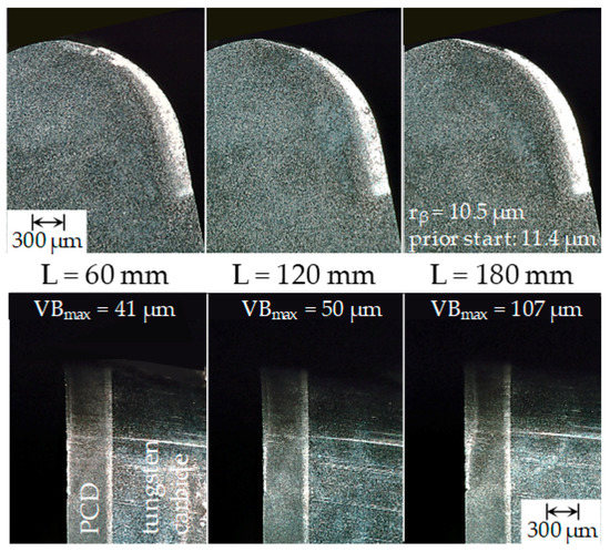
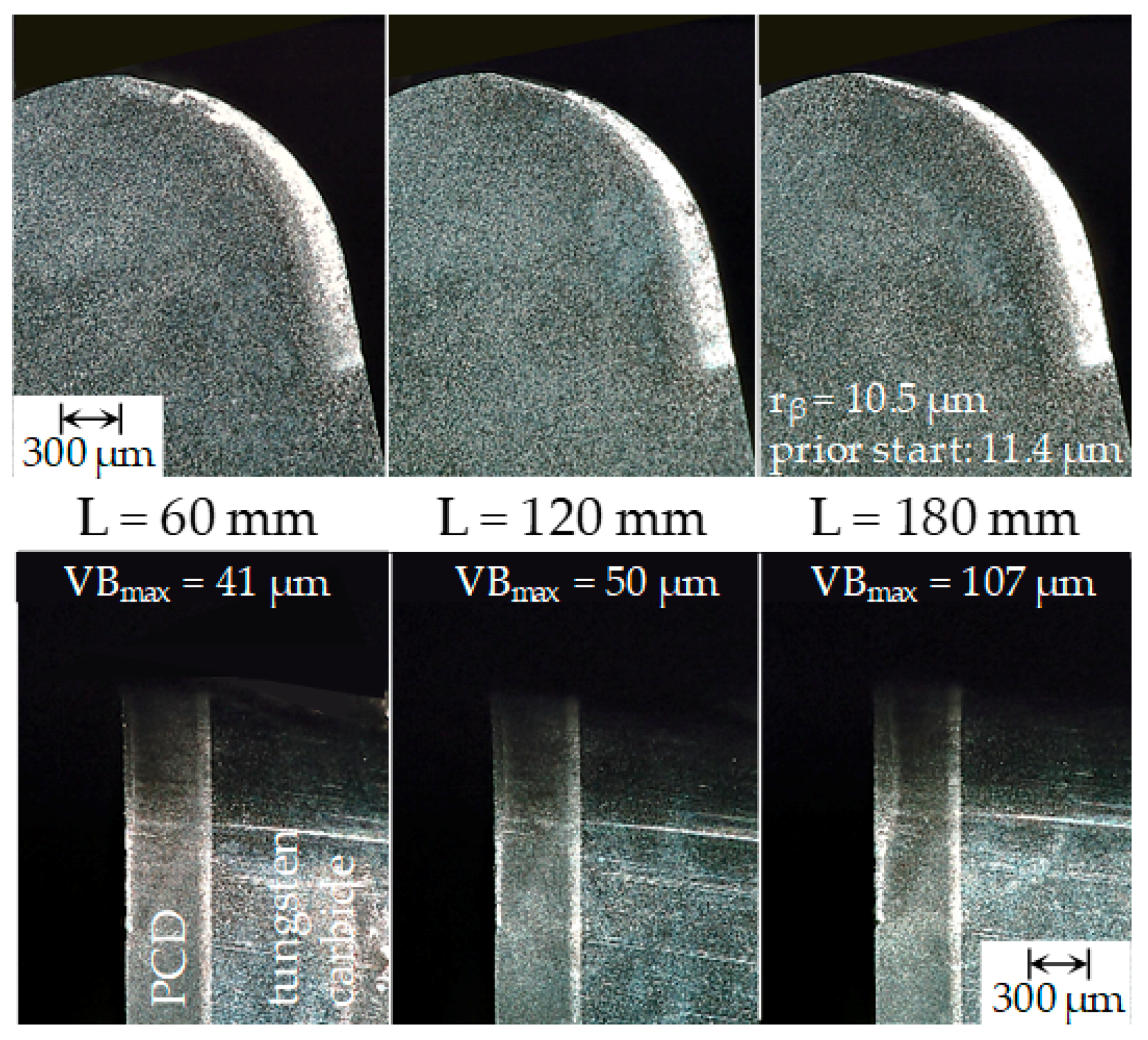
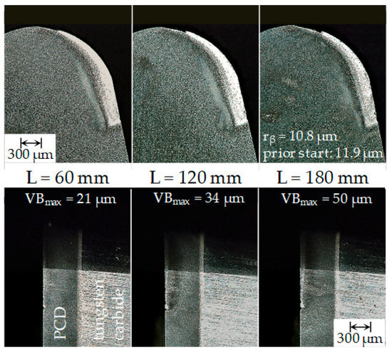
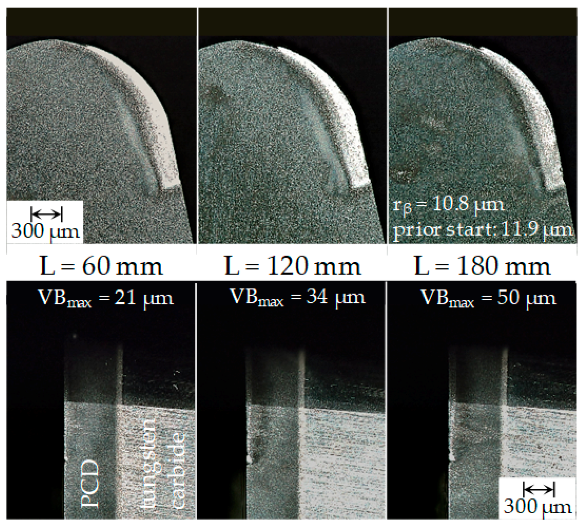
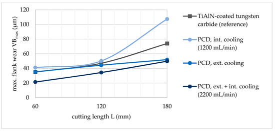
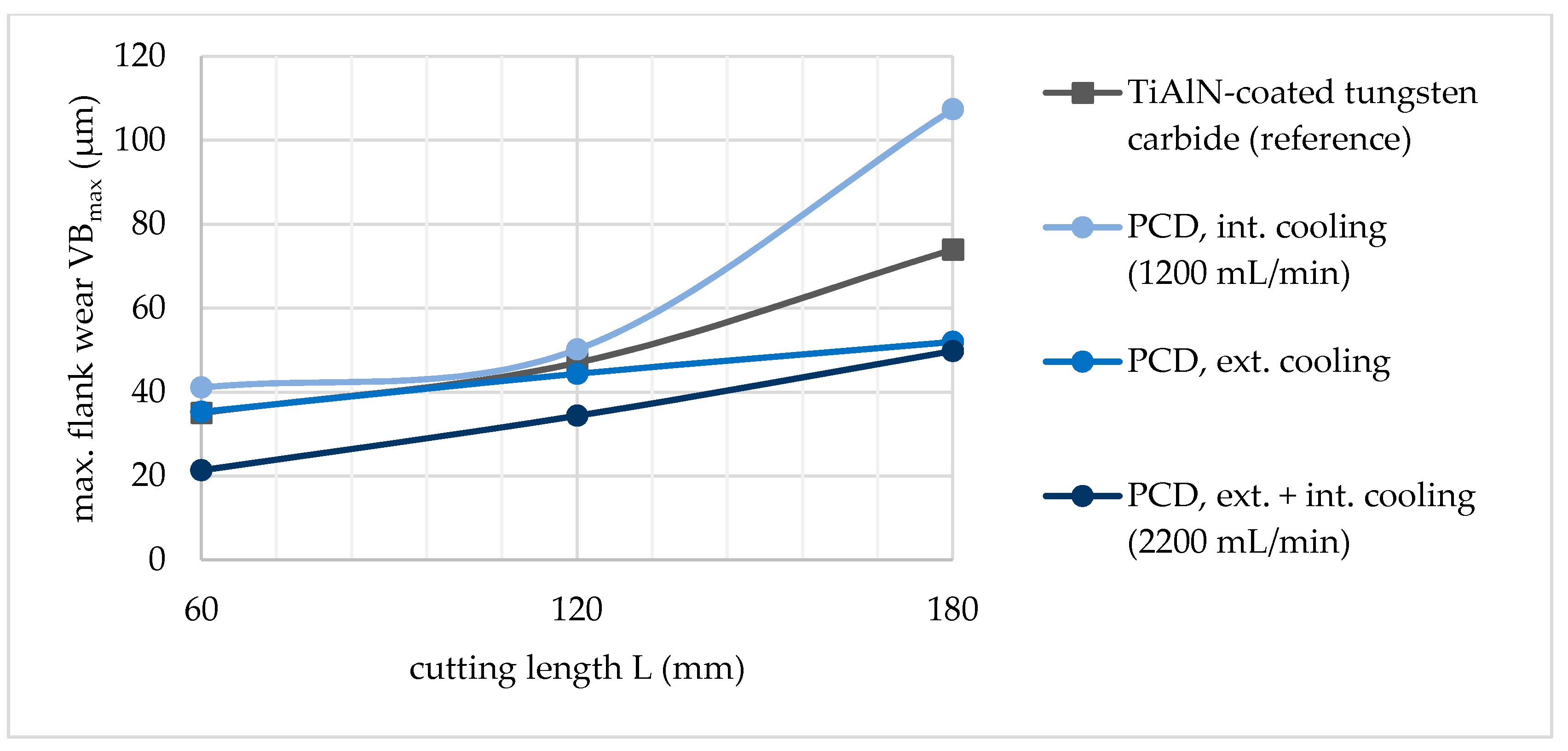
After each cutting length of 60 mm, the tool was dismantled and the tool wear was documented. The wear pattern on the rake and flank face were evaluated qualitatively, as shown in Figure 9, Figure 10 and Figure 11 (top—rake face, bottom—flank face). Subsequently, the tool was assembled to the machining center again and machining tests were continued. Corresponding to the initial tests, which were conducted with the combination of external and internal cooling, the extended tests showed a successful application of either external or internal cooling. Both versions ran in an adequate way compared to the reference process. In summary, the occurring measured maximum flank wear marks are illustrated in Figure 12.
Figure 9.
PCD cutting insert (external flood cooling, flow rate 22 L/min).
Figure 10.
PCD cutting insert (mainly internal cooling, flow rate internal cooling of 1200 mL/min).
Figure 11.
PCD cutting insert (external + internal cooling, flow rate internal cooling of 2200 mL/min).
Figure 12.
Progress of the maximum flank wear marks for various applied cooling strategies.
As depicted in Figure 12, the PCD cutting insert with solely external flood cooling already shows good wear behavior, especially in comparison to the versions with internal cooling and the expectable trend for a continuation of the cutting tests. The reason for this is the higher cooling performance due to increased coolant pump pressure and therefore, significantly higher cutting fluid flow rates for the external version. As such, as the cutting fluid flow rate is the lowest for the solely internally cooled PCD cutting insert (as the coolant pump pressure had to be lowered for leakage prevention), this ought to pose the reason why this alternative shows the highest occurring wear characteristics.
5. Conclusions and Outlook
Adequate cooling strategies with a PCD cutting insert, in which an internal cooling channel has been machined by EDM in the tungsten carbide substructure, enabled the machining of iron-carbon alloys with diamond cutting tools. By the investigated cooling strategies, the temperature in the cutting area at the cutting edge was decreased considerably below the critical temperature level of approximately 700 °C. The research work shows the significant potential of internally cooled diamond cutting inserts, which will be combined with minimum quantity lubrication in further investigations. This combination should have the benefits of effective process cooling arising from the internal cooling of the cutting insert on the one hand, and on the other hand a lubrication effect on the tool faces to reduce the occurring wear effects. When research work verifies the proof of concept shown here, the outstanding characteristics of diamond material could be used to gain increased quality and economic efficiency in the field of manufacturing engineering.
Author Contributions
Conceptualization, M.R. and F.B.; Formal analysis, J.B.; Funding acquisition, F.B.; Investigation, M.R.; Project administration, M.R.; Supervision, F.B.; Validation, M.R.; Visualization, M.R.; Writing—original draft, M.R.; Writing—review & editing, M.R. and F.B.
Funding
This research received no external funding.
Acknowledgments
The TU Wien as well as the authors want to express great appreciation and gratitude to the Machine Tool Technologies Research Foundation (MTTRF) for supporting the research work in the field of production engineering.
Conflicts of Interest
The authors declare no conflict of interest.
References
- Klocke, F.; König, W. Fertigungsverfahren 1, 8th ed.; Springer: Aachen, Germany, 2008. [Google Scholar] [CrossRef] [Scilit]
- Shimada, S.; Tanaka, H.; Higuchi, M.; Yamaguchi, T.; Honda, S.; Obata, K. Thermo-chemical wear mechanism of diamond tool in machining of ferrous metals. CIRP Ann. Manuf. Technol. 2004, 53, 57–60. [Google Scholar] [CrossRef] [Scilit]
- Abele, E.; Kulok, M.; Anton, P. Bearbeitung von Gusswerkstoffen mit Polykristallinen Schneidstoffen. ZWF Technol. Entwickl. 2007, 102, 540–545. [Google Scholar] [CrossRef] [Scilit]
- Heep, T.; Siebers, M. Einsatz kryogener Kühlstrategien bei der Schlichtbearbeitung von Vermicularguss mit polykristallinen Diamantschneidstoffen. Diam. Bus. 2015, 3, 7–10. [Google Scholar]
- Abele, E.; Schramm, B. Using PCD for machining CGI with a CO2 coolant system. Prod. Eng. 2008, 2, 165–169. [Google Scholar] [CrossRef] [Scilit]
- Bleicher, F.; Brier, J.; Siller, A. Simultaneous Machining of a Material Combination with an Internally and Externally Cooled Cutting Insert. Procedia CIRP 2016, 46, 15–18. [Google Scholar] [CrossRef] [Scilit]
- Bleicher, F.; Reiter, M. Wear reduction on cutting inserts by additional internal cooling of the cutting edge. Procedia Manuf. 2018, 21, 518–524. [Google Scholar] [CrossRef] [Scilit]
- Bleicher, F.; Pollak, C.; Brier, J.; Siller, A. Reduction of built-up edge formation in machining Al- and cast iron hybrid components by internal cooling of cutting inserts. CIRP Ann. Manuf. Technol. 2016, 65, 97–100. [Google Scholar] [CrossRef] [Scilit]

© 2018 by the authors. Licensee MDPI, Basel, Switzerland. This article is an open access article distributed under the terms and conditions of the Creative Commons Attribution (CC BY) license (http://creativecommons.org/licenses/by/4.0/).