1. Introduction
Silicone is widely used in variety of industries such as food, medical, and automotive, because of its good bio-compatibility, thermal insulation, stretchability, and chemical stability. One of the most common processes of manufacturing silicone parts is molding. However, it is difficult to use molding to manufacture parts with a complicated geometry or undercut features. There is an increasing demand for freeform silicone parts for applications including prototyping of fixtures, soft robotics [
1], wearable sensors [
2], drug delivery systems [
3], and personalized assistive devices [
4], etc. It is not cost effective to use molding to manufacture low-volume or personalized products. Therefore, additive manufacturing (AM) of silicone has drawn attention to overcome the limitations of traditional manufacturing processes for silicone.
Silicones can be categorized into one-part and two-part silicones. One-part silicones can be cured by external factors such as ultra-violet (UV) light, heat, or moisture. In two-part silicones, the materials do not cure until the two parts are mixed with a specific ratio. Extrusion-based processes are the most commonly used method for AM of silicone due to its simplicity and relatively low cost [
5,
6,
7,
8,
9,
10,
11,
12]. For one-part silicone, Vlasea et al. [
5] developed a pressure-flow model for extrusion-based 3D printing of silicone. Mannor et al. [
6] used extrusion-based silicone printing to produce a bionic model of the human ear. For two-part silicones, automated and precise mixing of the material is needed, such as using a progressive dual-cavity pump, which makes the process more complicated. WACKER CHEMIE AG (Munich, Germany) developed a process wherein part A silicone is extruded through a nozzle into a vat of part B silicone and becomes cured [
13]. McCoul et al. utilized a piezoelectric inkjet printing system for fabrication of silicone parts [
14].
Additive manufacturing of a part with overhang structures requires extra handling. Overhang structures are the areas of a part that are not supported by underlying layers and are defined by overhang angle and height. The overhang angle is defined as the angle between the part and the print bed. This angle can change when the printing orientation changes. The overhang height is the overall height of the overhang part. When an overhang structure is present and cannot be eliminated by changing the printing orientation, the use of support material is typically required. This problem also exists with printing soft materials, as well as parts with porous structures [
15]. A major limitation of the existing extrusion-based processes for AM of silicone is lack of a proper support material to produce parts that have overhang structures. Some research groups have attempted to develop AM processes that would overcome this limitation. Plott and Shih [
7] used a humidifier to enhance moisture curing and observed that bridging up to 10 layers of silicone can be done without the need of a support structure. Hamidi et al. [
16] used melted sugar as a support material to print silicone, but could only achieve limited dimensional and geometrical accuracy. Some research groups attempted to develop a hydrostatic AM process to create support-free soft structures [
17,
18,
19,
20]. One form of this process is extruding the print material inside a vat of another viscous material with a similar density, which acts as the support structure [
18,
20]. The hydrostatic pressure of the fluidic media physically stabilizes the printed soft material in a desired location [
19]. Due to the hydrostatic pressure inside the vat, the shape and the position of the printed part will be maintained without any support structures. Kim et al. [
20] developed a system to additively manufacture UV curable silicone while the part is floating in the middle of the vat and does not attach to the print bed. Vlasea et al. used the powder-bed binder jetting process to produce silicone structures [
21]. This method gives the freedom of design for complex parts, and eliminates the need for support structures [
22].
From the above literature review, it is demonstrated that AM of silicone for parts with overhang structures is still challenging. Because silicone is a soft material, the process parameters that are used in the typical AM process are not readily applicable. For example, when fabricating a rigid material, such as acrylonitrile butadiene styrene (ABS), a low infill density for the support structure is used to save material and printing time. Such a low infill density cannot be used when additive manufacturing silicone, as a large deflection can occur. Therefore, the goal of this study is to develop a low-cost extrusion-based AM process to fabricate silicone parts with overhang structures. Process parameters, including critical overhang angle and minimum infill density for the support material, are identified. Guidelines for whether the support structure is required for geometries with different overhang angles and heights will also be provided.
2. Methods
2.1. Materials
A one-part room-temperature-vulcanizing (RTV) silicone (Dow Corning® 732, Midland, MI, USA) was used in this study. RTV silicones start to cure once they are exposed to atmospheric moisture. Dow Corning 732 has a hardness of Shore A 25, a skin-over time of 7 min, a tack-free time of 20 min, and a tensile strength of 2.3 MPa when cured completely. A water-soluble material, poly-vinyl alcohol (PVA), (ESUN 3D FILAMENT, Shenzhen, China), was chosen to be investigated as the support material for 3D printing of silicone parts. PVA is commonly used as the support material for printing poly-lactic acid (PLA) material in the fused deposition modeling (FDM) process.
2.2. Experimental Setup
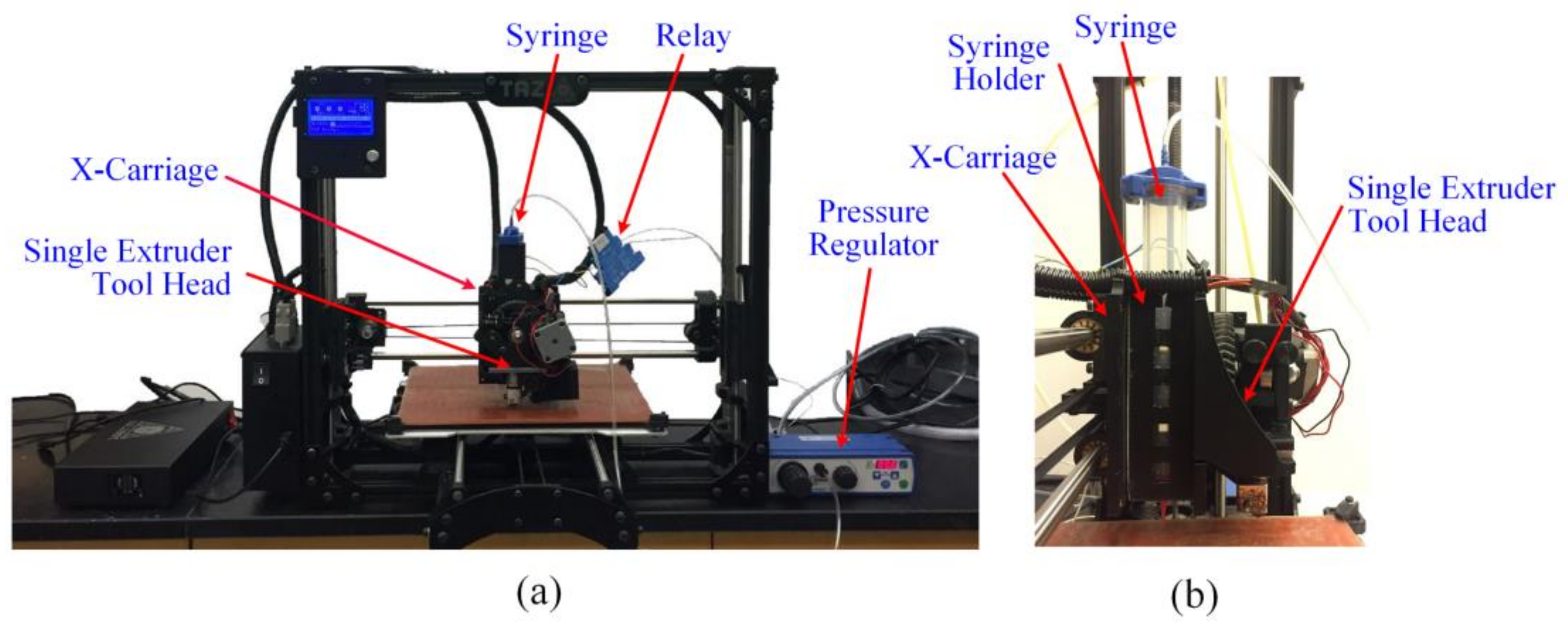
An overview of the experimental setup is shown in
Figure 1a. A Lulzbot TAZ5 (Aleph Objects, Inc., Loveland, CO, USA) was modified to incorporate a syringe holder for extrusion of silicone. The syringe holder was designed to hold a 25 mm diameter syringe (Optimum 55 cc, Nordson EFD, Westlake, OH, USA) and was attached to the single extruder tool head onto the X-carriage of the printer, as shown in
Figure 1b. Nozzles with three different sizes (0.2 mm, 0.35 mm, and 0.41 mm in diameters) were used in this study. A pressure regulator (Performus
TM III, Nordson EFD) was used to control the dispense of silicone during the printing process. The pressure regulator was connected to the printer’s control unit to automate silicone extrusion.
The printer firmware was updated to the dual-extruder setup. The original single extruder head, which was used to print the support material, and the silicone nozzle were calibrated to have a common home position following the manufacturer’s instructions. This step is important to ensure that both the build and support materials can be deposited without any misalignment. Cura 21.04 (Ultimaker, Geldermalsen, The Netherlands) was used to slice the CAD models and generate toolpaths, with the rectilinear infill pattern. It is critical for the support material (PVA) and the build material (silicone) to have an identical layer thickness, so that the parts built by the two materials are always at the same height upon finishing the printing process of each layer. The layer thickness of a silicone material is subject to the nozzle size, air pressure, and printing speed. These parameters were identified iteratively to achieve the desired layer thickness and are summarized in
Table 1, and used in this study.
2.3. Experimental Design
2.3.1. Adhesion Strength
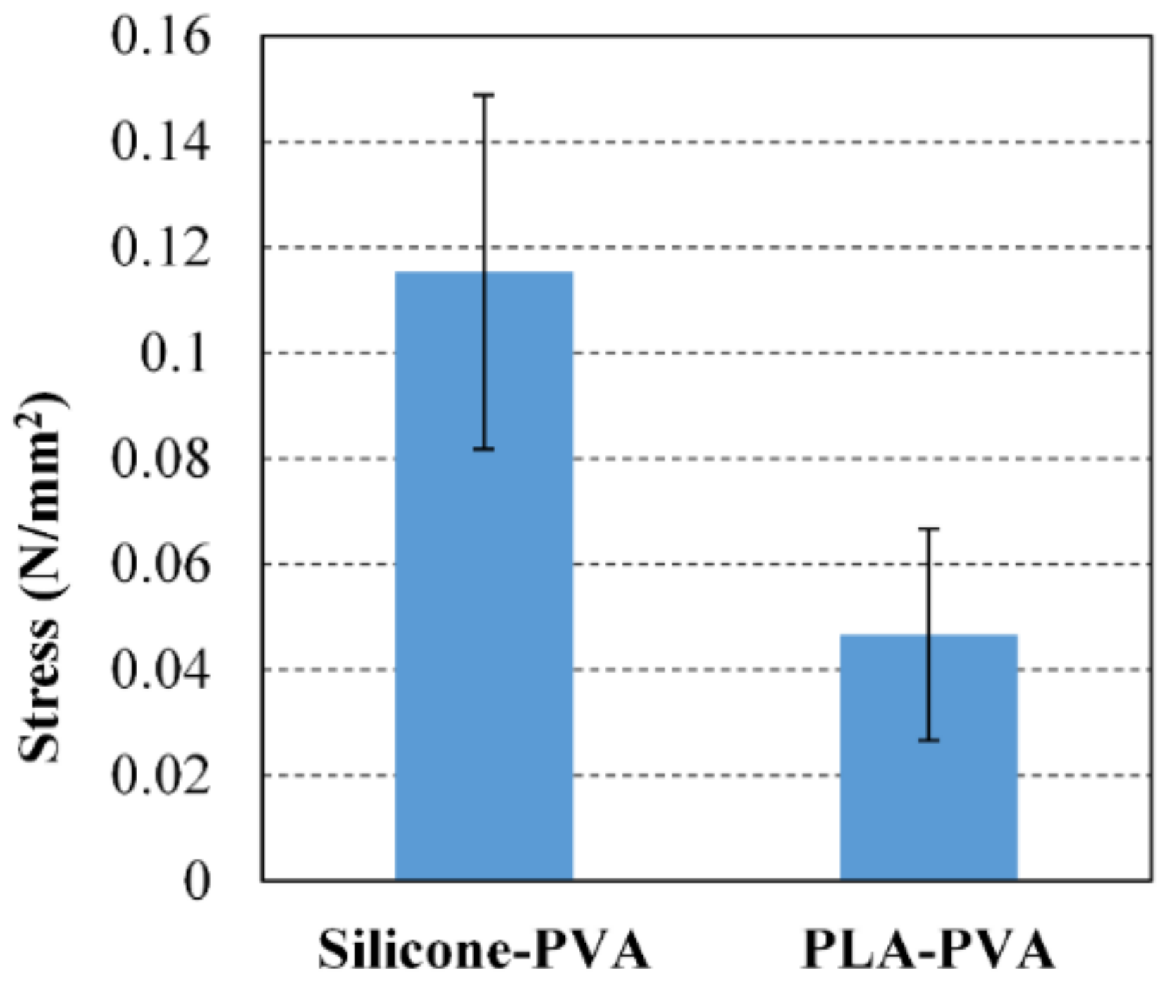
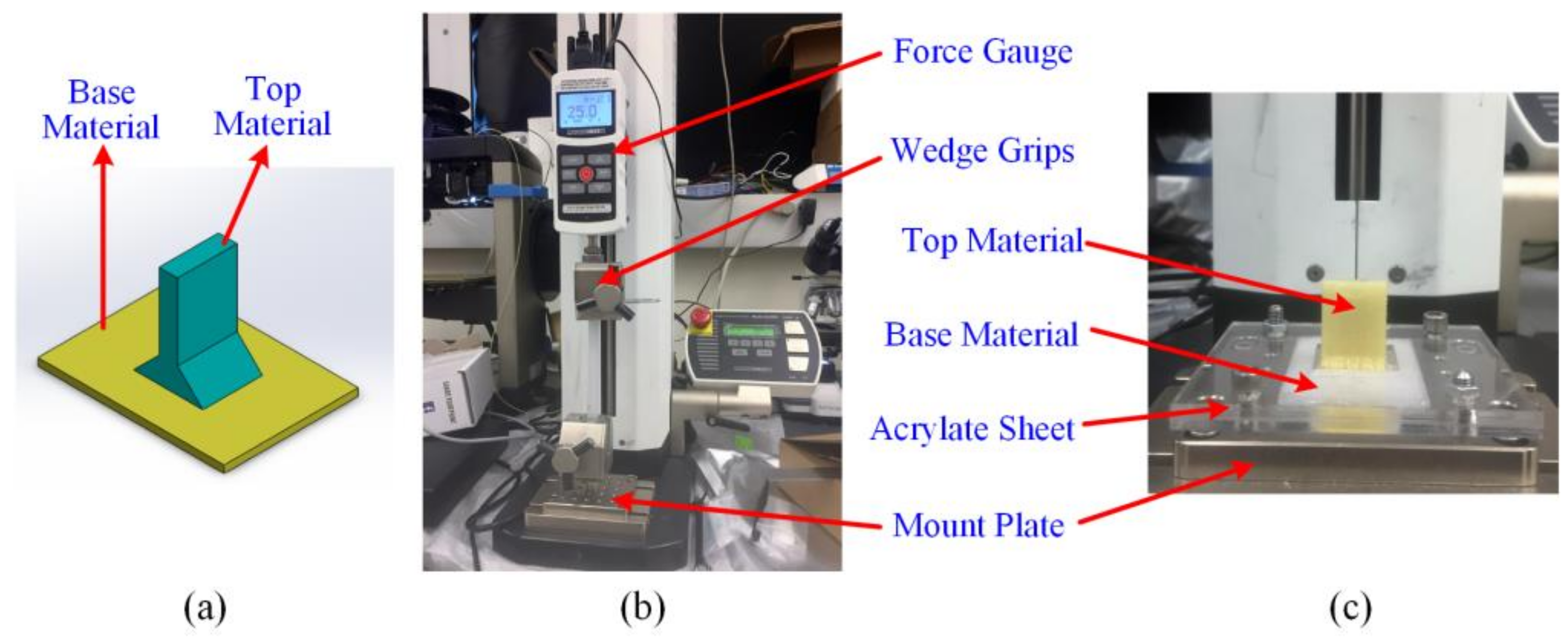
An adhesion test was designed and performed to determine the adhesion strength at the interface of the build and support materials. A proper adhesion strength between the build and support materials is necessary to ensure the printing quality. If the extruded silicone string does not adhere to the previously deposited support material, it will be torn out of the support material and dragged by the extruder head. As a result, the printing process will fail and cannot build a part successfully. In this test, the adhesion strength between silicone and PVA was tested and compared to that between PLA and PVA, a common combination of build and support materials used in the FDM process. The PLA filament used in this study was purchased from ESUN 3D FILAMENT.
Figure 2a shows the geometry of the test specimens that were used in the adhesion test. The interface between silicone and PVA has an area of 17 by 25 mm. The test specimens were printed with both silicone over PVA and PVA over silicone. In the case of PVA over silicone, PVA was printed on top of the silicone right after the last layer of silicone was printed so that the silicone was still in a state in which it was not completely cured yet. The printed specimens were left in ambient environment for two days before undergoing the adhesion test. The adhesion strength was measured using a tension/compression test machine (ESM303, MARK-10 Co., Copiague, NY, USA) with a force gauge (M5-200, MARK-10).
Figure 3b,c shows the experimental setup of the adhesion test. In this setup, the base material is clamped and secured between an acrylic plate and the mount plate of the tension/compression test machine. The top material was clamped by the wedge grip as close as to the interface as possible to reduce the effect of deformation within the test specimen.
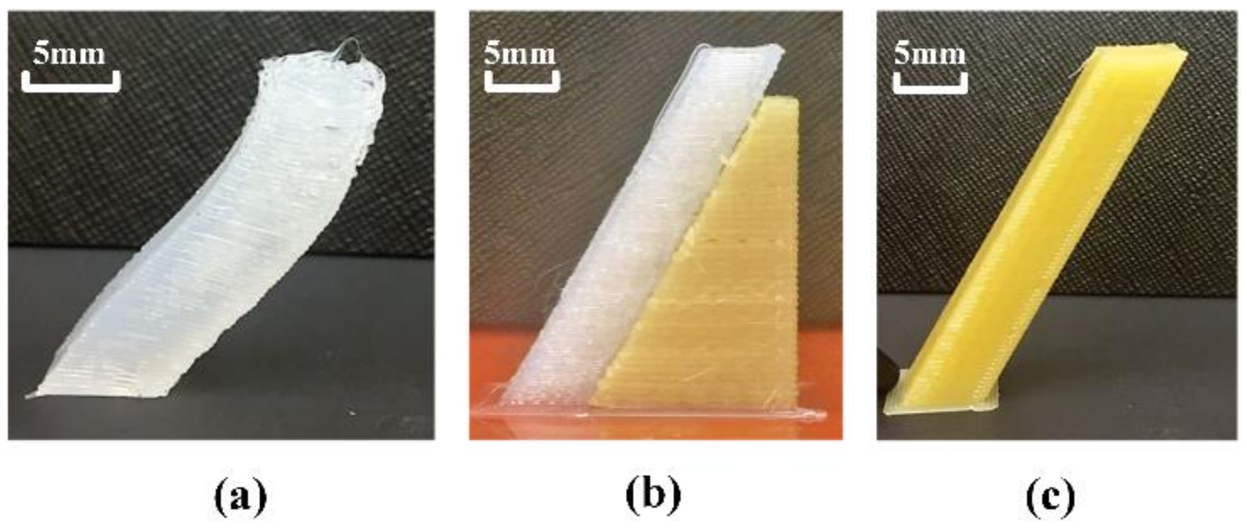
2.3.2. Critical Overhang Angle
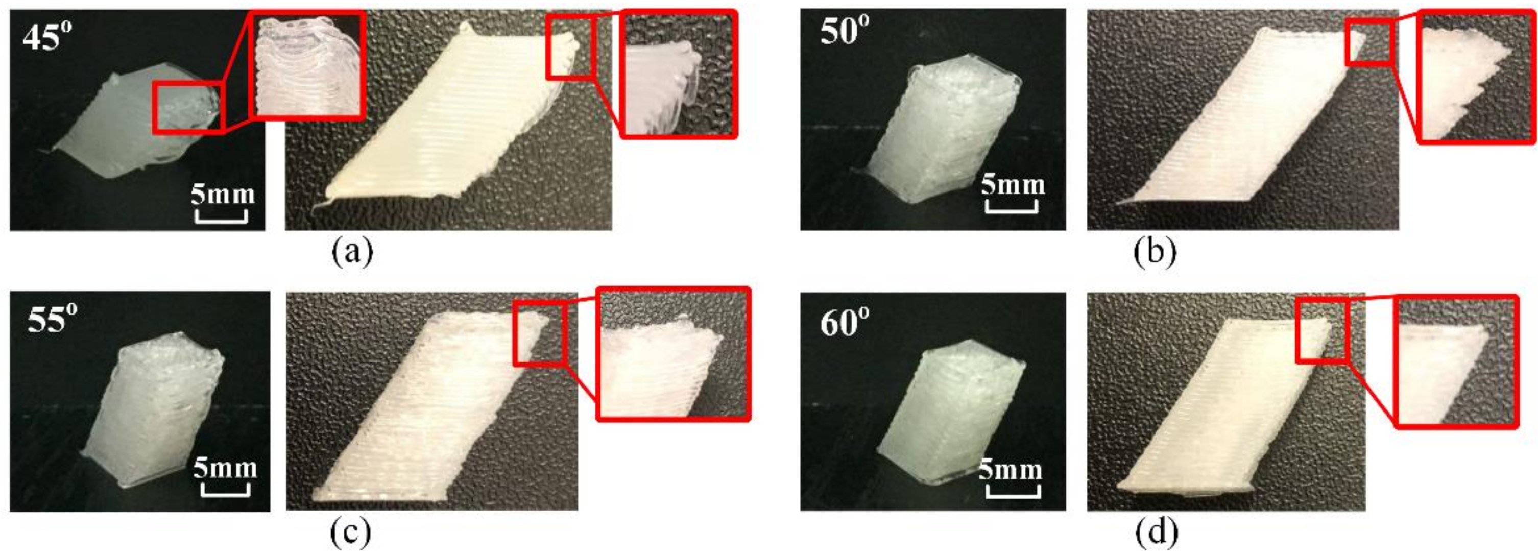
Critical overhang angle is the minimum angle of the overhang part for which a part can be printed without using any support materials. For the FDM process, most of the slicing software suggests building support structures for overhang angles of less than 45° by default. Because silicone is a soft material, it is expected that the critical overhang angle should be no less than that of the rigid materials. In this study, the critical overhang angle was identified experimentally by printing parallelogram samples, as shown in
Figure 1a, with a constant height of 15 mm and a base dimension of 7 by 10 mm, while varying the overhang angles from 45° to 60° in 5° increments. All of the samples were printed using the 0.2 mm nozzle and its associated parameters as listed in
Table 1. The smallest angle at which the part was printed successfully was determined as the critical overhang angle.
The samples of a height of 15 mm are short and the deflection due to gravity is considered negligible. Because of the soft nature of silicone materials, the amount of deflection increases as the overhang height increases. A significant deflection may become detrimental to the printing process, even though the overhang angle is above the critical overhang angle. Therefore, the identified critical overhang angle is only applicable to parts with limited heights. To examine the effect of the sample height on critical overhang angle, a parallelogram sample with a 60° overhang angle and a 30 mm height was printed using silicone and PVA, as a comparison. When the deflection of a part above a certain height is not negligible, the use of support material will be required. Therefore, for a sample with a given overhang angle, it is important to determine the maximum height that can be printed without support structure. This will be further studied by a finite element model in
Section 2.4.
2.3.3. Minimum Infill Density for Support Structure
Another critical parameter for printing silicone with an overhang structure is the infill density for the support structure. Because silicone is a soft material, when it is being printed, it can deflect in between the struts of the support structure. Therefore, if the support structure is printed in a low infill density, it will result in a failure of imprecise geometry. The higher the infill density is, the smaller the gaps of the printed structure are; however, more support material and a longer printing time are needed. As a result, it is critical to identify the minimum required infill density.
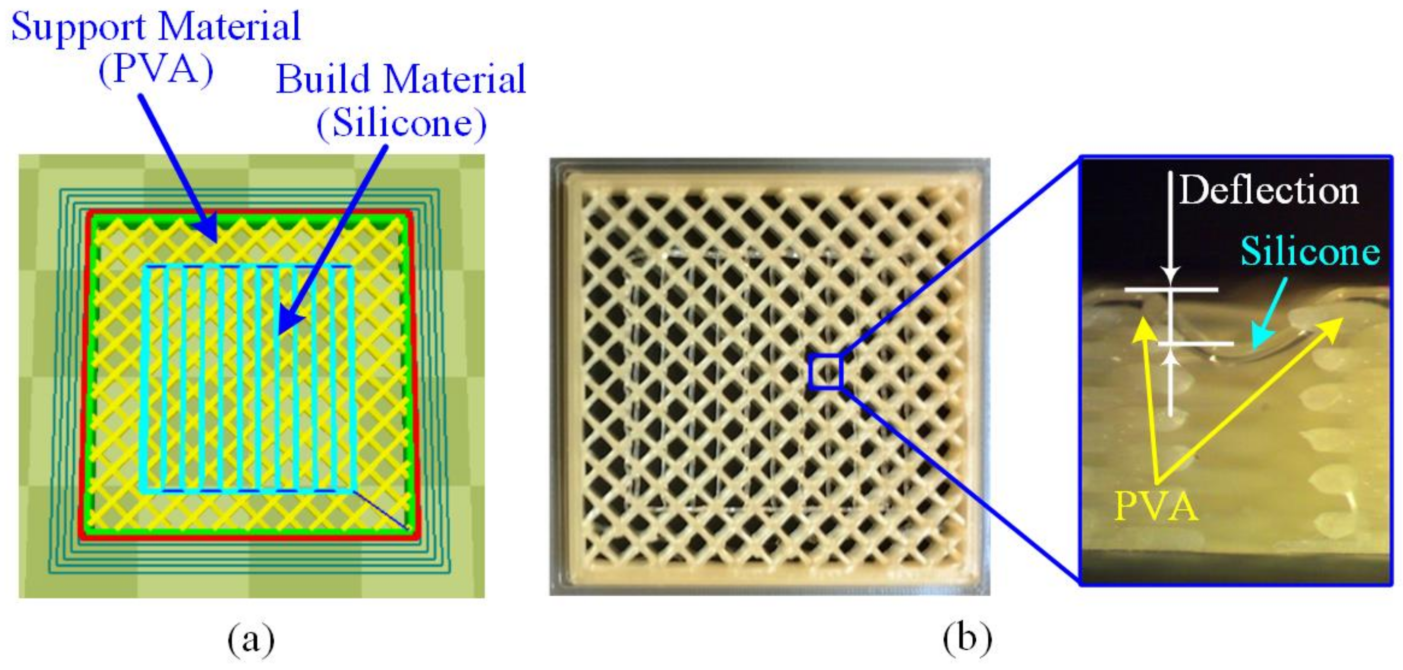
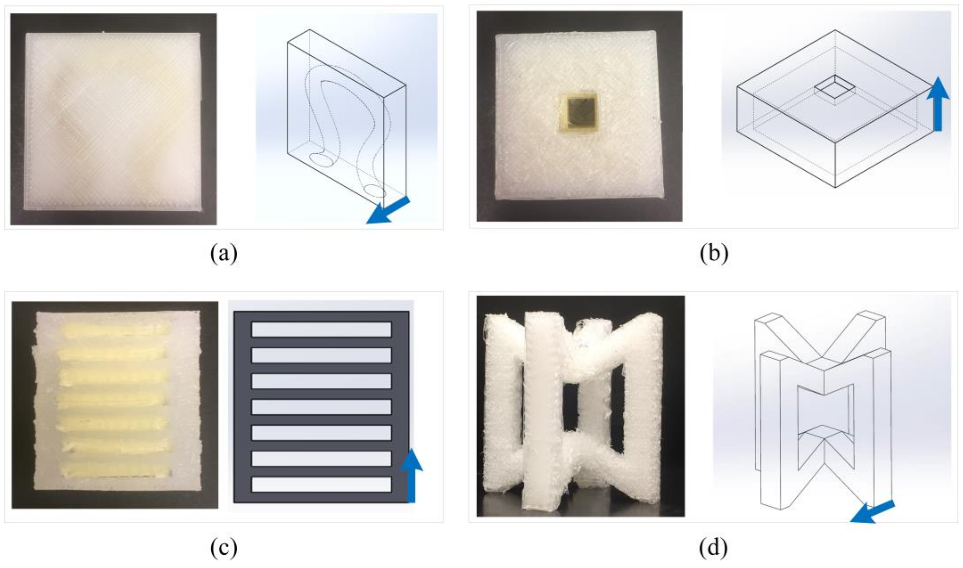
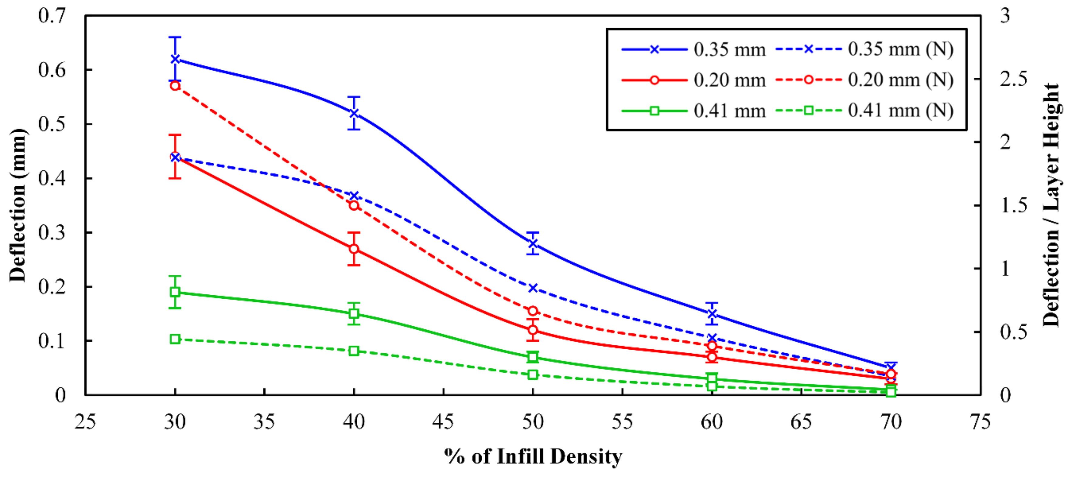
Typically, slicing software suggests an infill density of 30% for common FDM materials. To determine the minimum infill density for the support material for silicone, a simple model—as shown in
Figure 3a—was printed, with the infill densities of the support material varying from 30%, 35%, 40%, 50%, 60%, to 70% with a single layer of silicone on top of it. The samples were printed with different nozzle sizes of 0.2 mm, 0.35 mm, and 0.41 mm. After the samples were printed and cured for 24 h, the cross sections of the samples were sliced and examined under a stereomicroscope (SM-5TZZ-FOD-9M, AmScope, Irvine, CA, USA) to measure the deflection of silicone between the infill gaps, as shown in
Figure 3b. Deflection of less than 5% of the layer height was considered acceptable and the smallest infill density that fulfilled this criterion would be determined as the minimum infill density.
2.4. Finite Element Model
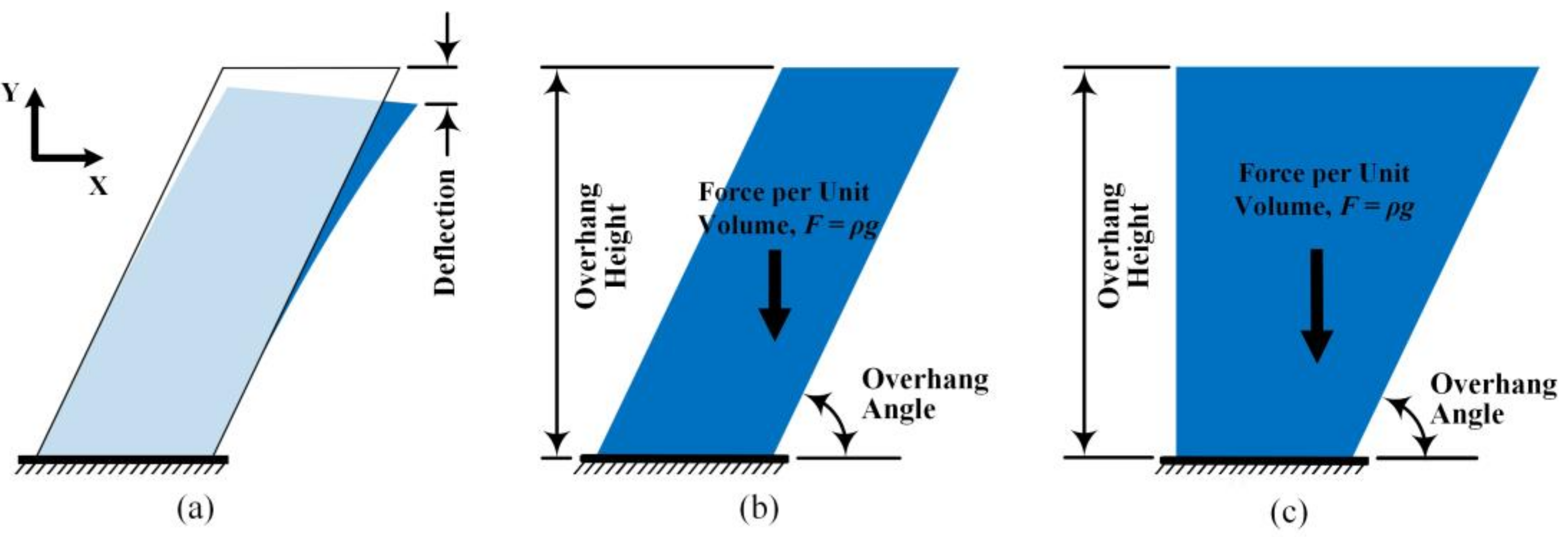
As mentioned in
Section 2.3.2, when the overhang height increases, the amount of deflection in the structure also increases because of the soft nature of silicone materials, as shown in
Figure 4a. The deflection leads to an increased distance between the nozzle and the part, and to the coiling effect, which happens when a viscous fluid thread falls onto a moving surface. The coiling effect has been studied and used to fabricate foam-like structures based on the unstable coiling patterns [
23,
24]. However, when the coiling effect happens, it is difficult to control the dimensional accuracy. To reduce the amount of deflection, a support structure is needed in order to print the part with a higher accuracy. For every given overhang angle, there is a maximum critical height that can be printed without support structure.
A finite element model was developed to estimate the amount of deflection due to gravity with two different shapes and different overhang heights and angles. The two shapes, one parallelogram and one right trapezoid, are shown in
Figure 4b,c, respectively. The two models have the same base and the heights of the models were varied from 10 mm to 25 mm, and the overhang angles were varied from 50° to 70°. In the finite element model, it is assumed that the print bed is stationary and the bottom of the silicone is constrained to the print bed with zero displacements in all directions.
The governing equations for this model are as follows:
where
s is stress tensor, and
F is the body force per unit volume. The body forces per unit volume is equal to
ρg, where
ρ is the density, and
g is the gravity. The strain tensor,
ϵ, is correlated to stress tensor by
where
C is the stiffness matrix and is calculated as follows:
where
ν is the Poisson ratio. This problem was simplified to a plane-strain problem, and the total strain tensor can be written in terms of displacement gradient as follows:
where
u is the displacement of any desired point.
The material properties of cured silicone were provided by the manufacturer (Dow Corning), which include density (ρ) of 1089 kg/m3, Poisson ratio (ν) of 0.49, and elastic modulus (E) of 330 kPa. To model the uncured silicone, 10% of elastic modulus of the cured silicone was used. Tetrahedral elements were used for the mesh. Depending on the height of the model, the number of the elements varied from 8253 to 13,629. COMSOL Multiphysics 5.3 (COMSOL Inc., Burlington, MA, USA) was used as the solver in this study.
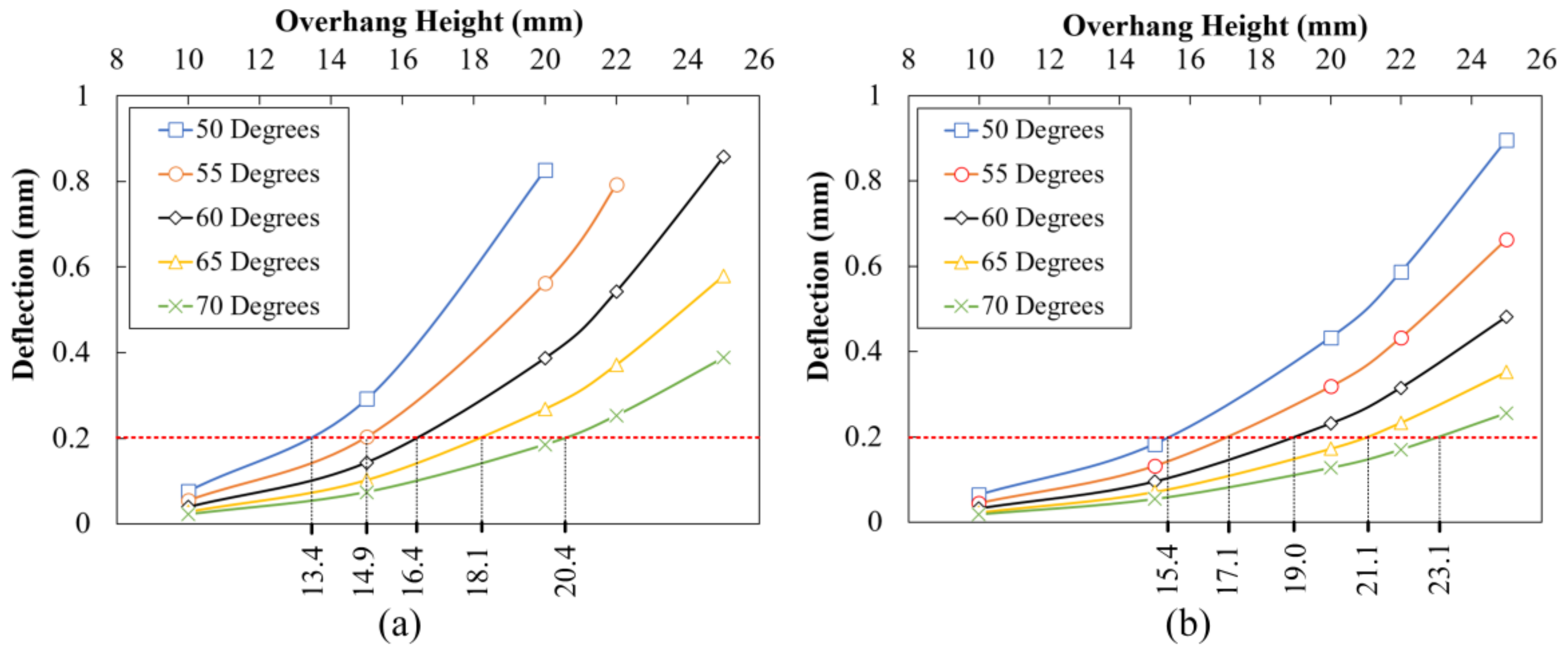
The deflection of the top-corner point in each sample (
Figure 4a) in
Y direction was evaluated in each model. It was assumed that the maximum permissible deflection is 0.2 mm, which is equal to the smallest nozzle size that is normally used. At each overhang angle, the height of the structure that results in 0.2 mm deflection was defined as the critical overhang height.
4. Discussion
A proper adhesion between the silicone and support material is critical to the quality of the printing process. If the adhesion force is not strong enough, the silicone in the nozzle can pull off the previously deposited material from the support structure and drag it as the nozzle moves. It should be noted that although the measured adhesion strength between silicone and PVA is considerably stronger than that of PLA and PVA, the actual strength during the printing process could be weaker than the measured value because silicone is still at the uncured state. However, because of the soft nature of silicone which prevents it from being held at the grippers, it is technically challenging to measure the adhesion strength between silicone and PVA in real time. On the other hand, from the example parts demonstrated in
Figure 10, it can be confirmed that an adequate adhesion strength can be formed between silicone and PVA, and therefore PVA can be used as a suitable support material for silicone. As PVA is a water-soluble material, the support structure can be removed by immersing the part into water. The time required to completely dissolve the support material depends on the complexity and structure of the part. For scaffold-like structures, extra rinsing can help to remove the support structure more quickly.
When generating the G-code to print a part, one important decision to make is whether the part requires the use of support structure. From the experimental results, it is concluded that, in general, a support structure is not required for overhang angles above 60° while the overhang height is less than 15 mm. However, when the overhang angle decreases or the overhang height increases, the deflection of the silicone part increases which causes an increase in the distance between the nozzle tip and the part, and thus the unintended coiling effect will occur and the part cannot be printed accurately. The decision on whether the support structure is needed cannot be made based solely on the overhang angle or the overhang height. Instead, both the overhang angle and height play a role in the amount of deflection and therefore, the need for support structures when printing overhang parts. In this study, only one nozzle size was used when identifying the critical overhang angle. When using a larger sized nozzle, the layer height as well as the stepover distance will increase, but the ratio between the layer height and stepover distance is determined by the overhang angle. Therefore, it is expected that the nozzle size does not have a significant effect on the critical overhang angle. However, when using a larger nozzle, a more conservative strategy can be used to ensure the printing quality.
The finite element model developed in
Section 2.4 was intended to provide a guideline to determine whether the use of a support structure is needed for parts with different overhang angles and heights. As shown in
Figure 9, the critical heights for different overhang angles and shapes are provided. For a 55° overhang angle, the critical height is 14.9 mm which agrees with the result shown in
Figure 6c. While it is impossible to simulate all different shapes, the two shapes used in this study represent two different cases which can be used as a framework for evaluating different geometries. The parallelogram shape is an unstable geometry in which the center of mass moves away from the base very quickly and the part tends to deflect more. The right trapezoid shape, on the other hand, is a more stable structure and can tolerate a larger overhang height with relative smaller deflection. If the printing quality or geometric accuracy are critical factors in the final product, a more conservative strategy can be implemented to ensure the printed part can meet all of the desired requirements.
There are other factors, such as configuration of the printer, toolpath pattern, and curing time, that could affect the amount of deflection and critical overhang angle and height accordingly. The configuration of the printer used in this study has a moving print bed in the
y-axis, as shown in
Figure 2a. The movement including acceleration and deceleration of the print bed can introduce vibration to the printed part and results in extra deflection. This effect could be alleviated by using a 3D printer with a stationary print bed, such as a delta printer. Therefore, the finite element analysis performed in this study only considers the deflection due to gravity which always exists regardless.
Once the need for a support structure is confirmed, the next decision is to select the infill density of the support structure. As shown in
Figure 8, the amount of deflection in the gap of support structures varies with the nozzle size and infill density. The minimum required infill density depends on the nozzle size. The 0.41 mm nozzle requires the least infill density among the three nozzle sizes. In addition to infill density, there are two factors that will affect the amount of deflection: the bead diameter (width/height) of silicone and the printing speed. For the printing speed, a lower printing speed will allow longer curing time of silicone which becomes stiffer and results in less deflection. For the bead diameter, there are two competing effects. First, the effect of the length to diameter ratio: when the diameter is larger, the ratio is lower and the deflection tends to be lower. Second, the curing time: when the diameter is small, the silicone bead can cure faster. In
Figure 8, the 0.40 mm nozzle has the least amount of normalized deflection, which can be attributed to the lower printing speed and smaller length to diameter ratio, which outweigh the effect of curing time. The 0.20 mm and 0.35 mm nozzles have similar amount of normalized deflections. This can be explained by the two competing effects that cancel each other. However, regardless of the nozzle size, the infill density for support material of silicone is still considerably higher than the infill density for printing other common FDM materials.
In comparison to the process of hydrostatic 3D printing of silicone [
17,
18], an advantage of using the extrusion-based process with a support structure is its dimensional accuracy, along with fewer process complications. The major issues within H3P of silicone are that (1) for sticky and viscous materials, it is very difficult to clean the part after it is printed, and (2) as the density of cured and raw material are not exactly the same, the part might change its position during the process, which affects the dimensional accuracy of the part. In order to achieve even better dimensional accuracy or part quality, a mechanical extruder can be used to have a more precise control on the material extrusion and reduce the likelihood of nozzle clogging. More studies can be done on studying the effect of tool path pattern on the meso-structure of silicone parts and the dimensional accuracy.
5. Conclusions
In this study, an additive manufacturing process to fabricate silicone parts with overhang structures is developed. The following procedures are suggested for printing silicone with overhang structure using PVA as the support material. First, the nozzle size can be determined based on the desired resolution or printing time. The layer height and printing speed can be subsequently determined. The part can then be oriented to have minimal required support structure. Based on this orientation, the overhang angle and height can be analyzed to determine whether the use of a support structure is required. If so, the infill density for PVA can be determined based on chosen nozzle size.
The following conclusions are reached:
A robust process, while using a simple printer setup, to additively manufacture silicone parts with overhang structures is developed.
PVA, a water-soluble material, is identified as a suitable support material for silicone as it provides sufficient adhesion strength with silicone.
A guideline to determine the necessity of a support structure based on the overhang angle and the overhang height is provided.
In the future, the geometric accuracy of the additive manufactured silicone parts can be further quantified. The meso-structure of the silicone part and different tool-path patterns can also be examined.


