

A Dynamic Checkpoint Interval Decision Algorithm for Live Migration-Based Drone-Recovery System
by
 , , , , , and
Bongjae Kim
1,† ,
,
Jungkyu Han
2,†,
Joonhyouk Jang
3,
Jinman Jung
4,
Junyoung Heo
5,
Hong Min
6,* and
Dong Sop Rhee
7,* 1
Department of Computer Engineering, Chungbuk National University, Cheongju 28644, Republic of Korea
2
Division of Computer and AI, Dong-A University, Busan 49315, Republic of Korea
3
Department of Computer Engineering, Hannam University, Daejeon 34430, Republic of Korea
4
Department of Computer Engineering, Inha University, Incheon 22212, Republic of Korea
5
Division of Computer Engineering, Hansung University, Seoul 04763, Republic of Korea
6
School of Computing, Gachon University, Seongnam 13306, Republic of Korea
7
Korea Institute of Civil Engineering and Building Technology, Goyang 10223, Republic of Korea
*
Authors to whom correspondence should be addressed.
†
These authors contributed equally to this work.
Drones 2023, 7(5), 286; https://doi.org/10.3390/drones7050286
Submission received: 21 March 2023
/
Revised: 20 April 2023
/
Accepted: 21 April 2023
/
Published: 24 April 2023
(This article belongs to the Special Issue UAV IoT Sensing and Networking)
Abstract
:Numerous services and applications have been developed to monitor anomalies or collect various sensing information in large-scale monitoring areas using drones. Nonetheless, interruptions of drone missions in such areas occasionally occur due to network errors, low battery levels, or physical defects, such as damage to the rotor and propeller. Checkpointing is a technique that periodically saves the system’s state, allowing it to be restored to that point in the event of a failure. In such circumstances, checkpointing techniques can be used to periodically save information related to the drone mission and replace a malfunctioning drone with the saved checkpoint information. In this paper, we propose a dynamic checkpoint interval decision algorithm for a live migration-based drone-recovery system. The proposed scheme minimizes the drone’s energy consumption while efficiently performing checkpointing. According to the basic experimental results, the proposed scheme consumed only about 3.51% more energy, while performing about 25.97% more checkpoint operations compared to the FIC (Fixed Interval Checkpointing) scheme. By using the proposed scheme, it is possible to increase the availability of checkpoint information and quickly resume drone missions, while minimizing the increase in energy consumption of the drone by saving checkpoints more frequently. Therefore, the proposed scheme can improve the reliability and stability of drone-based services.
1. Introduction
Various drone-based services are being studied and applied to real life [1,2]. Mobile devices such as drones have excellent mobility. This is why they are suitable for monitoring and collecting data over a wide area [3]. Various sensors, cameras, and network communication devices can be attached to devices such as drones, making it possible to collect various information from a large-scale monitoring area. For example, a drone with a camera attached can effectively perform roles such as detecting forest fires in large-scale monitoring areas such as mountains. Although it has these advantages, drones also have a considerable disadvantage in that they operate on a limited battery [4]. Therefore, the energy-consumption efficiency of drones is significant in drone-based services.
To ensure that a drone can continue to carry out its mission effectively, even in the event of software or hardware errors caused by energy depletion during monitoring or sensing, checkpointing techniques can be used to save and restore the drone’s mission status in advance. Many Virtual Machine (VM)-based checkpointing systems have been proposed [5], but these mechanisms are difficult to use for resource-constrained drones. This is because VM-based checkpointing requires more computing power, storage, and network bandwidth than lightweight container-based checkpointing mechanisms [6]. There are lightweight checkpointing systems; for instance, the CRIU (Checkpoint/Restore In Userspace) technique can be applied to drones [7]. Periodic checkpointing not only protects the executing processes from failures but also reduces wastage of resources by avoiding redundant execution of the same process [8]. The more frequently the drone generates and stores checkpoint information, the faster it can resume its previous mission [9]. However, frequent storing of checkpoint information may delay mission performance and consume additional energy [10]. Therefore, a checkpoint technique with a checkpoint interval that minimizes the energy consumption of the drone is required to efficiently resume the mission. In the case of drones, saving checkpoint information to the local device makes it difficult to resume the mission in case of hardware errors. For drones performing missions in large-scale monitoring areas, the checkpoint information should be transmitted to a remote DCC (Drone Control Center) for storage to overcome hardware errors or problems such as battery depletion while the drone is performing its mission [11]. When drones perform missions in large-scale monitoring areas, it may be difficult to communicate directly with the DCC [12], so they can communicate with Ground Stations (GS) scattered throughout the monitoring area to transmit the checkpoint information. Therefore, when deciding the checkpoint execution interval, it is necessary to dynamically adjust it, considering both the increase in energy consumption of the drone and the communication availability between the drone and the ground station.
In this paper, we propose a dynamic checkpoint interval decision algorithm for a live migration-based drone-recovery system. We show that an optimal checkpoint interval that minimizes the energy consumption of the drone exists by modeling the energy consumption of the drone according to the checkpointing interval and communication availability between the drone and the ground stations. The proposed scheme periodically attempts to transmit checkpoint information in consideration of communication availability with the Drone Control Center (DCC). Moreover, the proposed scheme dynamically adjusts the checkpoint execution interval based on the availability of communication with the ground stations when performing checkpointing. The main contributions of this paper can be summarized as the follows:
- Container-based lightweight migration mechanisms can improve the mission success rate of a drone such as an UAV-based delivery system [13]. The proposed scheme that is designed based on a container-based checkpointing mechanism can support a fast recovery to resume the most recent point of a faulty drone’s operation.
- When communication facilities are not sufficient to cover the entire monitoring area, a drone communicates with GSs opportunistically [14]. The proposed scheme can send the drone’s checkpoint image to the DCC via GSs without requiring the location information of the GSs.
- We adaptively adjust the checkpointing interval to maximize the number of successful checkpoint operations between a drone and a GS. The proposed scheme can increase the availability of the saved checkpoint image compared with the static checkpointing interval scheme.
To compare and analyze the performance of the proposed scheme, we compared it with Optimal Checkpointing (OPT) and Fixed Interval Checkpointing (FIC) schemes in terms of the energy consumption and the number of checkpoint operations performed. FIC is a scheme that performs checkpointing at a fixed interval without considering the communication availability between the GS and the drone. Therefore, in the case of FIC, the performance varies depending on the checkpoint interval used. OPT is a scheme that performs checkpointing when communication with the GS is possible without the need to check the availability of communication between the drone and the GS. Therefore, OPT always shows the best performance in terms of the energy consumption and the number of checkpoint operations performed when compared to the proposed scheme and the FIX scheme. The simulation results show that the proposed scheme can effectively perform periodic checkpointing while minimizing the increases in the energy consumption of a drone. Depending on the simulation environment for the drone’s mission, there were differences in performance among the OPT, FIC, and proposed schemes. It was confirmed that the reliability of the drone can be increased by increasing the number of checkpoint operations performed. According to the basic experimental results, the proposed scheme consumed a slightly higher amount of energy, approximately 3.51%, but performed a significantly greater number of checkpoint operations, approximately 25.97%, compared to the FIC scheme.
The rest of this paper is organized as follows. Section 2 describes existing checkpointing and migration schemes. Section 3 presents our system model for the proposed scheme and describes our dynamic checkpoint interval decision algorithm for live migration-based drone recovery. In Section 5, we present the results of our performance evaluation. In Section 6, we explain the constraints and limitations of the proposed scheme along with its advantages. Finally, in Section 7, we conclude the paper and discuss future works.
2. Related Works
2.1. Fault Diagnosis and Fault-Tolerant Control Methods
A drone consists of three main components: the main structure, sensors, and actuators. Ukaegbu et al. designed a drone prototype including these three components and conducted cost analysis and performance evaluation for each component to use the drone for real-world applications [15]. The drone located the target field and selectively sprayed herbicide using its camera module and a CNN-model-based target-detection algorithm. The research topics for fault diagnosis and fault-tolerant control have been studied by focusing on sensors and actuators, which are the primary sources of faults [1]. In terms of fault-tolerant control, there are two types of systems: passive and active systems. A passive system only reacts to predefined faults, while an active system detects and classifies faults to dynamically change system parameters [16].
In [17], the authors proposed both offline and online fault-detection schemes for predicting faults in the actuators (rotors) of a drone. In the offline method, predefined control criteria are used to analyze existing experimental results with various fault prospects. The offline method requires low computational power and immediately provides an optimal solution. In contrast, the online method detects a faulty rotor while the drone is running. However, the online method requires hardware modification and a lot of resources to maintain an online optimizer. Kim et al. proposed an energy-efficient adaptive wireless network interface selection scheme called AWNIS [18]. This method dynamically adjusts the detection period of available network interfaces to use more energy-efficient network interface. The proposed method improves the energy efficiency of mobile devices by dynamically selecting and using a more energy-efficient network interface.
Another approach is to focus on the accuracy of data. Wang et al. proposed a multivariate regression-based fault detection scheme for recovering flight data from a drone [19]. The authors estimated missing data and reduced noise by using long short-term memory with the residual filtering method. In another study, Wang et al. proposed a fault-tolerant UAV data acquisition scheme [20]. The authors attempted to find the optimal path to collect data from a terrestrial wireless sensor network. The next nearest-node-detection algorithm was used to determine the next position of the UAV, and fault tolerability was improved by reducing communication loss.
There are various machine-learning-based methods for fault diagnosis and fault-tolerant control. Yang et al. proposed an intelligent fault diagnosis method based on a stack denoising auto-encoder to reduce information loss, and a Convolutional Neural Network (CNN) model to improve training speed and accuracy [21]. The authors converted a one-dimensional time-domain signal collected by four rotors into a two-dimensional grayscale image to improve fault diagnosis accuracy with limited data sets. Hua et al. proposed a method that combines the backpropagation neural network and the genetic algorithm to detect faults in sensors equipped with a drone [22]. The authors adjusted the coding method by changing parameters such as crossover and variant operators to improve accuracy. Arani et al. proposed a 3D trajectory planning scheme using a reinforcement learning algorithm to maximize the energy efficiency of drones [23]. Drones adaptively adjust their velocities and locations based on the reinforcement learning algorithm to provide a network connection to ground users who cannot reach the terrestrial BS due to interference.
A fault recovery system was proposed for a leader–follower-based multiple drone system. If one of the drones experiences an unrecoverable engine problem, the remaining drones reconfigure their positions to bypass the faulty drone [24]. Redundancy is a critical solution for fault-tolerant control to ensure mission success for drones. In [25], the authors estimate a sufficient redundancy level for nonlinear systems using a fault recoverability measure. The number of backup drones added does not guarantee mission success in a linear way. The authors applied a nonlinear model to estimate the effect of redundancy. Tousi et al. proposed an optimal hybrid fault-recovery scheme for swarm drones [26]. In this scheme, drones cooperate to accomplish the desired mission. This hybrid system is composed of a low-level and a high-level fault recovery system. The low-level system uses controller parameters to recover a member of the group. In the high-level system, a discrete-event system model is used to estimate the minimum recovery cost of a faulty drone. Huang et al. proposed a drone loss detection and auto-replacement protocol for a communication network of multiple drones [27]. In the detection step, drones exchange heartbeats and fuse neighbors’ response and their data to detect a lost drone. In the auto-replacement step, a task from the lost drone is assigned to a drone that runs the lowest-priority task.
Table 1 shows a comparison of features between our approach and previous studies. Hardware fault-detection schemes do not consider communication issues between a drone and ground base stations. In the case of data-accuracy improvement, path planning, and clustering schemes, the authors assume static links and a single type of communication method between a drone and ground base stations. However, network connectivity is limited in real-world applications [28,29]. Therefore, we designed a process for storing states to resume from the recently saved state under opportunistic network environments, although issues related to multiple drones remain for future work.
2.2. Lightweight Migration Schemes
Checkpointing scheme is a fault-tolerable methods to improve the sustainability of a drone. The checkpointing scheme saves a snapshot (checkpoint) of an application status as files and restarts (restore) the application from the checkpoint in the case of failures. Periodically saved checkpoints protect the executing process from failures and reduce the resource waste from the redundant execution of the same process [8]. However, the checkpointing cost increases with the scale and the frequency of checkpointing [30]. Live migration refers to the process of moving a running task from one host to another host without downtime [31]. There are three levels of live migration: Virtual Machine (VM) migration, container migration, and user-space migration. VM migration has significant performance problems with the seamless hand-off, and container migration is lightweight and able to provide a specific degree of isolation [32]. However, these two techniques are still heavy when using them for live migration for drones. Checkpoint/Restore In User-space (CRIU) enables the checkpointing of Linux processes within a single namespace [33]. CRIU saves the status of a process to a set of files forming the checkpoint including file descriptors, memory maps, child processes, thread, and so on. CRIU can implement the post-copy live-migration technique. In [34], the authors implemented a live migration system between two remote servers by using CRIU. Experimental results showed that checkpoint and restore performance of CRIU is lighter than VM and container-based live migration in terms of CPU, memory, and network bandwidth. We also designed our checkpoint-and-restore system based on CRIU for live migration because the lightweight feature of CRIU properly applies to a drone system.
3. System Model
In this section, we explain our system model for our dynamic checkpoint interval decision algorithm. We also demonstrate through mathematical analysis that there exists a checkpoint execution interval that minimizes energy consumption of the drone. Table 2 shows the notations and descriptions used in the system model.
3.1. Assumptions and System Service Scenarios
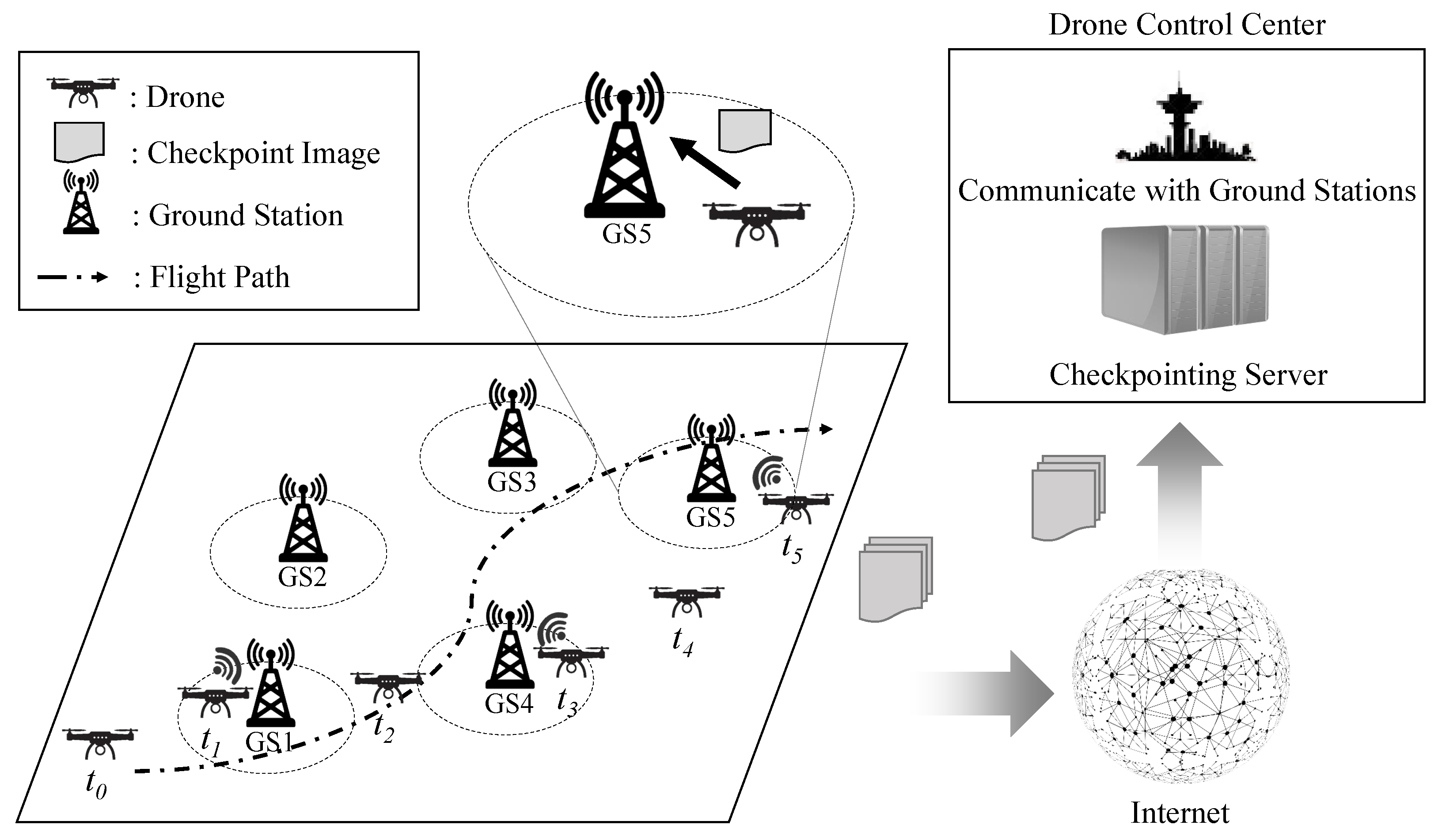
Figure 1 shows an example of the service scenario of the proposed scheme, where the drone performs monitoring or data collection missions while flying over a large-scale monitoring area. As it moves, the drone can communicate with the GS (Ground Station) to send the monitored data or its checkpoint information as an image of the current task execution status. The GS then sends this information to the DCC (Drone Control Center). In the event of a failure due to battery shortage, etc., a replacement drone can use the valid checkpoint information stored in the DCC to resume the mission instead of the failed drone.
In this service scenario, we assume that the drone does not have prior knowledge of the location information of the GSs that transmit monitoring or checkpoint information. Based on this assumption, the proposed scheme dynamically adjusts the checkpoint execution interval by estimating the communication availability between the drone and the Ground Stations even without knowing the location information of the GSs.
3.2. Checkpointing Success Probability Model According to Checkpoint Interval
Depending on the movement of the drone, it is possible to create a model consisting of two states: the state in which the drone can communicate with the GS and the state in which communication is not possible. This can be modeled based on the two-state model proposed by Kim et al. in [18]. Figure 2 shows the two-state diagram of the possibility of communication between the drone and the GS. As shown in Figure 2, it consists of two states, each of which is the Communication Disabled State (CDS) and the Communication Enabled State (CES). We assume that the initial state of the drone is the Communication Disabled State (CDS) state. We also define the checkpoint cycle. One checkpoint cycle is defined as the transition of the drone’s state from the CDS to the CES state and performing one checkpoint operation. Therefore, the drone’s state continuously transitions between the CDS and CES states and the iteration of the checkpoint cycle repeats according to the movement of the drone, as shown in Figure 1.
The probability that the drone is in the CES state with the GS after t seconds equals the transient state probability of the Continuous Markov Process (CMP). Equation (1) is the probability that the drone is in the CDS state after t seconds when it is in the CDS state. Similarly, Equation (2) is the probability that the drone is in the CES state after t seconds when it is currently in the CDS state. Therefore, when the possibility of communication with the GS is checked to perform checkpointing at an interval of , the probability that communication is possible and the probability that communication is impossible can be calculated as in Equations (3) and (4), respectively.
3.3. Drone Energy Consumption Model
The energy consumption of a drone can be modeled by composing four main components as shown in Equation (5). Our goal is to minimize the drone’s energy consumption and find the optimal checkpointing interval , which is used to check the possibility of communicating with the GS to perform the checkpointing. Our goal is expressed by Equation (6).
Each operation checking the possibility of communication with the GS can be considered a Bernoulli trial. Therefore, in the case of checking whether communication with the GS is possible or not in a interval, the expected value of the number of attempts to check the communication possibility until communication with GS is possible on average can be calculated using Equation (7). The average expected time that the drone is in the CDS state, , can be calculated as shown in Equation (8). The average expected time that the drone is in the CES state, , can be calculated as in Equation (9) according to the memoryless property of exponential distribution [35,36]. Although the drone moves to carry out its mission, it continues to perform its task in both CDS and CES states. The expected total energy consumption of the drone to perform a given mission, can be expressed by Equation (10). can be expressed by Equation (11). It can be calculated by dividing the checkpoint image’s size () by the drone’s communication speed with the GS () and multiplying the energy consumption () in the time unit used for data transmission. can be calculated as Equations (12). and can be expressed by Equations (13) and (14), respectively.
3.4. Mathematical Analysis of the Proposed Energy Consumption Model
In this subsection, we show that there is a detection interval for checking the possibility of communication with the GS to perform a checkpointing operation that minimizes the energy consumption of the drone by mathematically analyzing the proposed energy consumption model of the drone. Table 3 shows the parameters and their values used in the mathematical analysis. and were set based on [18]. Other parameters were set to reflect various environments in which drones can perform their missions.
Figure 3 shows the energy consumption according to the size of the checkpoint information, where , , and J. As shown in Figure 3, as the size of the checkpoint image decreases, it can be seen that using a shorter minimizes the overall energy consumption of the drone. For example, a value that minimizes energy consumption is about 48 s in the case of MB. A value that minimizes energy consumption is about 56 s in the case of MB. This implies that performing checkpoint operations at shorter intervals is more desirable because it results in lower energy consumption required for checkpointing and transmitting checkpoint images to the GS.
Figure 4 shows the energy consumption results according to the and , where MB and J. In Figure 4, means that is about 500 s and is about 500 s, respectively. In other words, the energy consumption is same when is and is . As shown in Figure 4, It can be seen that , which minimizes the energy consumption, becomes shorter as decreases and increases.
Figure 5 shows the energy consumption results according to the total amount of energy required for the initial start of the drone, where , , and MB. If the drone’s checkpoint information is not valid, it is necessary to restart its mission from the beginning. Therefore, it is required to perform the checkpoint frequently as the cost of restarting the drone’s mission from the beginning increases. As shown in Figure 5, that minimizes the drone’s energy consumption becomes shorter as increases. For example, that minimizes energy consumption is about 32 s in the case of J. In the case of J, that minimizes energy consumption is about 55 s.
Figure 3, Figure 4 and Figure 5 show that there is a checkpoint execution interval that minimizes drone energy consumption, depending on various factors such as initial start cost and checkpoint image size. Therefore, it is necessary to perform checkpoints dynamically by adjusting the checkpoint execution interval to minimize the increase in drone energy consumption while considering various factors in the drone’s mission environment.
4. Dynamic Checkpoint Interval Decision Algorithm
In this section, we present our dynamic checkpoint interval decision algorithm. Algorithm 1 shows the proposed algorithm, and Table 4 lists the notations and their descriptions used to explain it. We will provide a detailed explanation of the operation process of our dynamic checkpoint interval decision algorithm.
As shown in Algorithm 1, it initializes the variables , t, i, and in lines 1 to 4. represents the current value of the checkpoint execution interval. t represents the current time value, and i represents the current checkpoint cycle value. The remaining steps demonstrate how the drone dynamically adjusts the checkpoint interval and performs checkpointing during the mission.
| Algorithm 1: Proposed dynamic checkpoint interval decision algorithm |
 |
Lines 6 to 13 of the algorithm work as follows: If the drone is in the CDS state and the current time t reaches the checkpoint execution time, the drone checks for connection availability with the GS. If communication with the GS is possible, the drone changes its state to CES, sets up a communication link, checkpoints its current state, and sends the corresponding information to the GS.
Lines 17 to 26 of the algorithm work as follows: If the network connection with the GS is disconnected (line 18), the drone changes its state to CDS. Then, it calculates the times and during the current i-th checkpoint cycle. The algorithm calculates and as described in lines 20 and 21 and approximates and using the expressions in lines 22 and 23. The algorithm then calculates the for the current situation (lines 24–25) and resets to this value.
By repeating this process, the proposed method dynamically adjusts the checkpoint interval and performs checkpointing during the mission. The coefficient reflects the ratio of the latest and when updating and . As the value increases, and have a stronger influence on the update. The value needs to be set appropriately, and we used a value of 0.1 in our performance evaluation. The performance change due to the proposed method according to the change in the value is explained in more detail in the performance evaluation.
In our dynamic checkpoint interval decision algorithm, the most time-consuming part is finding the optimal value of , denoted as , based on Equation (6) described in line 24 of the algorithm. This process involves calculating the predicted energy consumption of the drone by incrementally increasing the value of the checkpoint execution interval from the minimum to the maximum, using Equation (6). Therefore, if the number of values of the checkpoint execution interval that need to be checked is n, the time complexity of the algorithm is . As a result, it can be easily applied to real-world applications due to its low time complexity.
Figure 6 shows a flowchart of the proposed scheme. As shown in Figure 6, the drone performs its mission based on the proposed scheme while periodically carrying out checkpointing operations. Before performing its mission, the drone goes through an initialization process, such as setting the initial checkpoint execution interval related to its mission. The drone then checks whether it has reached the checkpoint execution time and whether it can continue its mission. When it is time to perform the checkpoint, the drone performs a checkpoint operation and transmits the checkpoint image to the DCC via GS. If communication with the Ground Station (GS) is unavailable at that time, the checkpoint cannot be finally executed. After performing the checkpointing operation, the drone approximates the communication availability with the GS and readjusts the optimal checkpoint execution interval. As shown in Figure 6, if the drone is unable to continue its mission, a substitute drone is prepared by using the latest checkpoint image stored in the DCC. Then, a substitute drone takes over the mission, and the current drone quits the mission.
5. Performance Evaluation
5.1. Performance Evaluation Environments
We conducted simulations to compare and analyze the performance of the proposed scheme. Our simulation scenario for the proposed scheme is depicted in Figure 1. Table 5 shows parameters used in the simulation and their descriptions. and were set based on [18]. For , we set the power consumption considering devices that can be used for drone missions, such as Jetson Xavier. Generally, the energy consumption of Jetson Xavier ranges from 10 W to 30 W. For , we set it to 100 J, assuming that it would take about 5 s for the drone to resume the mission using the saved checkpoint information. Other parameters were set to reflect various environments in which drones can perform their missions.
We compared the proposed scheme to two other schemes in terms of the average energy consumption and the number of checkpoint operations performed:
- Fixed Interval Checkpointing (FIC): a scheme that performs checkpointing at a fixed interval without considering the communication availability between the drone and the GS.
- Optimal Checkpointing (OPT): a scheme that performs a checkpoint when communication with the GS is possible without the need to check the availability of communication between the drone and the GS.
For convenience, we will refer to the Fixed Interval Checkpointing scheme as FIC and the Optimal Checkpointing scheme as OPT in this paper. The Fixed Interval Checkpointing (FIC) scheme performs checkpointing at a fixed interval without considering the communication availability between the drone and the GS. Therefore, the performance in terms of energy consumption or the number of performed checkpoint operations varies depending on the checkpoint intervals used. On the other hand, we assume that the Optimal Checkpointing scheme performs a checkpoint when communication with the GS is possible without the need to check the availability of communication between the drone and the GS. Thus, it can minimize the energy consumption when compared to the proposed scheme and the FIC scheme. Furthermore, compared to the proposed scheme and the FIC scheme, the OPT scheme is capable of performing the highest number of checkpoint operations. Each experiment was performed 10 times, and the average value was used for performance evaluation.
5.2. Performance Evaluation Results
5.2.1. Basic Performance Results
Figure 7 shows the simulation results when , MB, J, and s. As shown in Figure 7a, the energy consumptions of OPT, ours, and FIC are about 20.40 J/s, 21.23 J/s, and 20.51 J/s, respectively. As shown in Figure 7b, the number of performed checkpointing operations of OPT, ours, and FIC are about 3026, 2861, and 2271, respectively. Among the three schemes, OPT showed the best performance in terms of energy consumption and the total number of checkpoint operations performed. In terms of energy consumption, the proposed scheme consumed about 4.04% more energy compared to the OPT scheme. When compared to the FIC scheme, the proposed scheme consumed about 3.51% more energy. The OPT scheme performed about 5.79% more checkpoint operations compared to the proposed scheme. The proposed scheme performed about 25.97% more checkpoint operations than the FIC scheme. In summary, compared to the FIC scheme, the proposed scheme has an increase in energy consumption due to the dynamic adjustment of the checkpoint execution interval but can perform more checkpoint operations to increase the availability of checkpoint information.
5.2.2. Performance Results According to the Coefficient Value
Figure 8 shows the simulation results according to the coefficient value when MB, J, s, and . As the coefficient value, alpha, which affects the performance of the proposed scheme, increased, both the energy consumption and the number of checkpointing operations performed by the proposed scheme increased. As the value increased, the increase in the number of checkpointing operations performed relative to the increase in energy consumption tends to decrease. In order to balance the trade-off between increasing energy consumption and the number of checkpoint operations, a proper value for must be set to maximize the number of checkpoint operations compared to the increasing energy consumption. Therefore, in the following experiments, all experiments were conducted with the value set to 0.1.
5.2.3. Performance Results According to the Checkpoint Execution Interval of FIC
Figure 9 shows the simulation results of the FIC scheme at different checkpoint execution intervals, with MB, J, and . As shown in Figure 9, the energy consumption of the FIC scheme increases as the checkpoint execution interval decreases, and the total number of performed checkpoints also increases. When the checkpoint execution interval of the FIC scheme is 5 s, the energy consumption of the FIC scheme is almost the same as our proposed scheme, but the FIC scheme performs fewer checkpointing operations. Specifically, the proposed scheme performed 16 more checkpointing operations than the FIC scheme. When compared with the proposed method, as the checkpoint execution interval of FIC becomes longer, the performance in terms of the total number of performed checkpointing operations decreases significantly.
5.2.4. Performance Results According to the Number of GS
Figure 10 shows the simulation results according to the number of GSs when = 80 MB, J, and s. As shown in Figure 10, when the total number of GS increases, it can be seen that the overall number of checkpointing operations performed increases. This is because the higher the number of GSs, the higher the probability that the drone can communicate with the GS and thus perform checkpointing more frequently. The proposed scheme dynamically adjusts the checkpointing interval according to the network environment, so that even as the number of GSs increases, it does not show a tendency to increase energy consumption. However, the OPT and FIC schemes show a tendency to increase energy consumption as the total number of GSs increases. The proposed scheme consumed approximately 4.43% more energy than FIC on average, but it performed approximately 29.80% more checkpointing operations on average. The proposed scheme consumed an average of about 5.12% more energy than the OPT Scheme, and the OPT scheme performed an average of about 5.49% more than the proposed scheme in terms of the number of checkpointing operations performed. In summary, while the proposed scheme may not perform as well as the OPT scheme, it can effectively increase the number of checkpointing operations while minimizing the energy consumption of the drone compared to the FIC scheme.
5.2.5. Performance Results According to the Initial Start Costs
Figure 11 shows the simulation results according to the initial start costs when MB, s, and . As the initial start cost increases, it is more advantageous to perform checkpoints more frequently in terms of recovery costs for responding to drone error situations. As shown in Figure 11, in the proposed scheme, as the initial start cost increases, it uses a bit more energy, but it can be observed that it performs more checkpoint operations. In other words, it can be observed that the proposed scheme can dynamically adjust the checkpointing interval well by considering the initial start cost.
5.2.6. Performance Results for Different Checkpoint Image Sizes
Figure 12 illustrates the simulation results according to the checkpoint image size when , J, and s. As shown in the figure, overall energy consumption increased as the size of the checkpoint image increases. This is because the time it takes for drones to create the checkpoint image and transmit it to the ground station increases with the size of the checkpoint image. The time it takes for drones to create the checkpoint image and transmit the generated checkpoint image to the ground station also increases.
Comparing the proposed scheme with FIC and OPT schemes showed that the energy consumption was about 3.35% and 4.13% higher when the size of checkpoint image was 40 MB. When the size of the checkpoint image was 320 MB, the proposed scheme consumed about 4.42% and 3.53% more energy compared to FIC and OPT, respectively. As the size of the checkpoint image increased, the performance gap between the proposed scheme and OPT in terms of energy consumption decreased. This is because the energy consumption of generating each checkpoint image and transmitting it to the DCC through the GS became relatively larger than the periodic checkpointing operation costs.
5.2.7. Performance Results According to the Speed of the Drone
Figure 13 shows the simulation results according to the speed of the drone. As depicted in Figure 13, all OPT, FIC, and the proposed scheme demonstrated an increase in energy consumption and the number of performed checkpointing operations as the maximum speed of the drone increased. The reason for obtaining such results is that as the maximum speed of the drone increases, it can monitor a wider area multiple times. Therefore, it can obtain more opportunities to communicate with the GS and perform more checkpointing operations by communicating with the GS.
In terms of the total number of performed checkpointing operations, it was shown that the relative performance of the proposed method improves as the speed of the drone increases. When comparing the proposed scheme with OPT, it was found that the relative performance of the proposed scheme improved as the maximum speed of the drone increased in terms of the total number of checkpointing operations performed. At a maximum drone speed of 5 m/s, OPT performed about 5.31% more checkpointing operations than the proposed scheme, while at a maximum drone speed of 20 m/s, OPT performed about 2.58% more checkpointing operations than the proposed scheme. In summary, the performance gap between OPT and the proposed method decreased. This shows that the proposed scheme works effectively even when the speed of the drone is fast.
6. Discussion
The advantage of the proposed scheme is that it works even without prior information, such as the location of the ground stations. However, the proposed scheme also has the following limitations and constraints. Although the proposed scheme can dynamically adjust the checkpoint execution interval to ensure communication feasibility with the Ground Stations, periodic checking is still required. Therefore, if the location information of the Ground Station is known in advance, the proposed scheme can be improved by allowing the drone to use its GPS-based location information to check the communication feasibility with the Ground Stations and perform checkpointing. In this case, additional computing costs are incurred as the drone continuously calculates its position based on GPS information and checks communication feasibility with nearby Ground Stations.
Additionally, during drone missions, there are other factors that affect energy consumption, such as those required for controlling and moving the drone. Controlling and moving a drone consumes a significant amount of energy, which varies depending on factors such as wind speed and the drone’s altitude. The proposed dynamic checkpoint interval decision algorithm in this paper has a limitation: it only considers the energy consumption required for application-level tasks and periodic checkpointing, without taking into account the energy consumption for motor control to maintain the drone’s attitude according to the drone’s altitude, wind speed, and other factors. However, it is possible to include the energy consumption required for controlling the drone in the proposed scheme, while considering factors such as the drone’s altitude and wind speed. In summary, even if factors such as the drone’s altitude and wind speed are reflected in the energy consumption model required for the drone’s mission, the operation procedures and structure of the proposed scheme largely remain unchanged.
7. Conclusions and Future Works
In this paper, we propose a dynamic checkpoint interval decision algorithm for a live migration-based drone recovery system. The proposed method can dynamically adjust the checkpoint execution interval by considering the communication availability between the drone and the Ground Station. We compared the performance of our proposed scheme with the OPT (Optimal) and FIC (Fixed Interval Checkpoint) schemes. Although our proposed scheme showed lower performance than the OPT method in terms of energy consumption and the number of checkpointing operations performed, it demonstrated the ability to perform more frequent checkpointing while minimizing the increase in drone energy consumption by dynamically adjusting the checkpoint interval, compared to the FIC scheme. Although the performance evaluation results varied slightly depending on the experimental environment, based on the basic experimental results, the proposed scheme consumed approximately 3.51% more energy and performed about 25.97% more checkpoint operations compared to the FIC scheme. Therefore, it is expected that the proposed scheme will effectively reduce the number of missions to be performed again when resuming the mission due to hardware errors in the drone.
Since the proposed scheme can operate effectively even without prior knowledge of the ground station’s location that supports drone communication, it is expected to perform the drone’s mission effectively in monitoring environments where the drone performs its mission for the first time. In future work, we plan to analyze and evaluate how much the loss of performed missions can be reduced when drone missions are resumed through additional modeling.
Author Contributions
Conceptualization, B.K., J.H. (Jungkyu Han), and H.M.; methodology, B.K. and J.H. (Jungkyu Han); software, B.K. and H.M.; validation, J.J. (Jinman Jung), J.H. (Jungkyu Han), and J.H. (Junyoung Heo); formal analysis, B.K., J.J. (Joohyouk Jang) and J.H. (Jungkyu Han); investigation, B.K., J.J. (Joohyouk Jang) and H.M.; resources, J.H. (Jungkyu Han), H.M. and J.J. (Jinman Jung); data curation, B.K., J.J. (Joohyouk Jang) and H.M.; writing—original draft preparation, B.K., J.H. (Jungkyu Han) and H.M.; writing—review and editing, B.K., H.M., J.H. (Jungkyu Han) and J.J. (Jinman Jung); visualization, B.K.; supervision, H.M., J.J. (Jinman Jung), J.H. (Junyoung Heo) and D.S.R.; project administration, J.H. (Junyoung Heo); funding acquisition, J.H. (Junyoung Heo) and D.S.R. All authors have read and agreed to the published version of the manuscript.
Funding
This research was supported by the Korea Agency for Infrastructure Technology Advancement (KAIA) grant funded by the Ministry of Environment(Grant RS-2019-KA153746).
Institutional Review Board Statement
Not applicable.
Informed Consent Statement
Not applicable.
Data Availability Statement
Not applicable.
Conflicts of Interest
The authors declare no conflict of interest.
References
- Balamuralidhar, N.; Tilon, S.; Nex, F. MultEYE: Monitoring System for Real-Time Vehicle Detection, Tracking and Speed Estimation from UAV Imagery on Edge-Computing Platforms. Remote Sens. 2021, 13, 573. [Google Scholar] [CrossRef]
- Kinaneva, D.; Hristov, G.; Raychev, J.; Zahariev, P. Early Forest Fire Detection Using Drones and Artificial Intelligence. In Proceedings of the 2019 42nd International Convention on Information and Communication Technology, Electronics and Microelectronics (MIPRO), Opatija, Croatia, 20–24 May 2019; pp. 1060–1065. [Google Scholar] [CrossRef]
- Kim, B.; Jung, J.; Min, H.; Heo, J. Energy Efficient and Real-Time Remote Sensing in AI-Powered Drone. Mob. Inf. Syst. 2021, 6650053, 1–8. [Google Scholar] [CrossRef]
- Chen, Y.; Baek, D.; Bocca, A.; Macii, A.; Macii, E.; Poncino, M. A case for a battery-aware model of drone energy consumption. In Proceedings of the 2018 IEEE International Telecommunications Energy Conference (INTELEC), Turino, Italy, 7–11 October 2018; pp. 1–8. [Google Scholar]
- Tao, Z.; Xia, Q.; Hao, Z.; Li, C.; Ma, L.; Yi, S.; Li, Q. A Survey of Virtual Machine Management in Edge Computing. Proc. IEEE 2019, 107, 1482–1499. [Google Scholar] [CrossRef]
- Uchibayashi, T.; Apduhan, B.; Suganuma, T.; Hiji, M. Experiments and Evaluation of a Container Migration Data-Auditing System on Edge Computing Environment. Computers 2023, 12, 27. [Google Scholar] [CrossRef]
- Puliafito, C.; Mingozzi, E.; Vallati, C.; Longo, F.; Merlino, G. Virtualization and Migration at the Network Edge: An Overview. In Proceedings of the 2018 IEEE International Conference on Smart Computing (SMARTCOMP), Taormina, Italy, 18–20 June 2018; pp. 368–374. [Google Scholar] [CrossRef]
- Di, S.; Robert, Y.; Vivien, F.; Cappello, F. Toward an Optimal Online Checkpoint Solution under a Two-Level HPC Checkpoint Model. IEEE Trans. Parallel Distrib. Syst. 2017, 28, 244–259. [Google Scholar] [CrossRef]
- Ahmed, A.; Mohan, A.; Cooperman, G.; Pierre, G. Docker Container Deployment in Distributed Fog Infrastructures with Checkpoint/Restart. In Proceedings of the 2020 8th IEEE International Conference on Mobile Cloud Computing, Services and Engineering (MobileCloud), Oxford, UK, 3–6 August 2020; pp. 55–62. [Google Scholar] [CrossRef]
- Geldenhuys, M.K.; Thamsen, L.; Kao, O. Chiron: Optimizing Fault Tolerance in QoS-aware Distributed Stream Processing Jobs. In Proceedings of the 2020 IEEE International Conference on Big Data (Big Data), Atlanta, GA, USA, 10–13 December 2020; pp. 434–440. [Google Scholar] [CrossRef]
- Abro, G.E.M.; Zulkifli, S.A.B.M.; Masood, R.J.; Asirvadam, V.S.; Laouti, A. Comprehensive Review of UAV Detection, Security, and Communication Advancements to Prevent Threats. Drones 2022, 6, 284. [Google Scholar] [CrossRef]
- Nguyen, M.T.; Nguyen, C.V.; Do, H.T.; Hua, H.T.; Tran, T.A.; Nguyen, A.D.; Ala, G.; Viola, F. UAV-Assisted Data Collection in Wireless Sensor Networks: A Comprehensive Survey. Electronics 2021, 10, 2603. [Google Scholar] [CrossRef]
- Li, R.; Li, X.; Xu, J.; Jiang, F.; Jia, Z.; Shao, D.; Pan, L.; Liu, X. Energy-aware decision-making for dynamic task migration in MEC-based unmanned aerial vehicle delivery system. Concurr. Comput. Pract. Exp. 2020, 33, 1–18. [Google Scholar] [CrossRef]
- Mukherjee, A.; De, D.; Dey, N. DewDrone: Dew Computing for Internet of Drone Things. IEEE Consum. Electron. Mag. 2023, 12, 52–57. [Google Scholar] [CrossRef]
- Ukaegbu, U.F.; Tartibu, L.K.; Okwu, M.O.; Olayode, I.O. Development of a Light-Weight Unmanned Aerial Vehicle for Precision Agriculture. Sensors 2021, 21, 4417. [Google Scholar] [CrossRef]
- Merheb, A.R.; Noura, H. Active Fault-Tolerant Control of Quadrotor UAVs Based on Passive Controller Bank. In Mechanism, Machine, Robotics and Mechatronics Sciences; Rizk, R., Awad, M., Eds.; Springer International Publishing: Cham, Switzerland, 2019; pp. 231–241. [Google Scholar]
- Mazeh, H.; Taghirad, H.D.; Sahili, J. Offline and Online Active Fault Tolerant System For Multirotor Drones. In Proceedings of the 2021 9th RSI International Conference on Robotics and Mechatronics (ICRoM), Tehran, Iran, 17–19 November 2021; pp. 151–156. [Google Scholar] [CrossRef]
- Kim, B.; Cho, Y.; Hong, J. AWNIS: Energy-Efficient Adaptive Wireless Network Interface Selection for Industrial Mobile Devices. IEEE Trans. Ind. Inform. 2014, 10, 714–729. [Google Scholar] [CrossRef]
- Wang, B.; Liu, D.; Peng, Y.; Peng, X. Multivariate Regression-Based Fault Detection and Recovery of UAV Flight Data. IEEE Trans. Instrum. Meas. 2020, 69, 3527–3537. [Google Scholar] [CrossRef]
- Wang, Z.; Yu, J.; Lin, S.; Dong, J.; Yu, Z. Distributed Robust Adaptive Fault-Tolerant Mechanism for Quadrotor UAV Real-Time Wireless Network Systems With Random Delay and Packet Loss. IEEE Access 2019, 7, 134055–134062. [Google Scholar] [CrossRef]
- Yang, P.; Wen, C.; Geng, H.; Liu, P. Intelligent Fault Diagnosis Method for Blade Damage of Quad-Rotor UAV Based on Stacked Pruning Sparse Denoising Autoencoder and Convolutional Neural Network. Machines 2021, 9, 360. [Google Scholar] [CrossRef]
- Hua, L.; Zhang, J.; Li, D.; Xi, X.; Shah, M.A. Sensor fault diagnosis and fault tolerant control of quadrotor UAV based on genetic algorithm. J. Sens. 2022, 2022, 8626722. [Google Scholar] [CrossRef]
- Hajijamali Arani, A.; Azari, M.M.; Hu, P.; Zhu, Y.; Yanikomeroglu, H.; Safavi-Naeini, S. Reinforcement Learning for Energy-Efficient Trajectory Design of UAVs. IEEE Internet Things J. 2022, 9, 9060–9070. [Google Scholar] [CrossRef]
- Tahir, A.; Böling, J.; Haghbayan, M.H.; Plosila, J. Development of a Fault-Tolerant Control System for a Swarm of Drones. In Proceedings of the 2020 International Symposium ELMAR, Zadar, Croatia, 14–15 September 2020; pp. 79–82. [Google Scholar] [CrossRef]
- Tahavori, M.; Hasan, A. Fault recoverability for nonlinear systems with application to fault tolerant control of UAVs. Aerosp. Sci. Technol. 2020, 107, 106282. [Google Scholar] [CrossRef]
- Tousi, M.; Khorasani, K. Optimal hybrid fault recovery in a team of unmanned aerial vehicles. Automatica 2012, 48, 410–418. [Google Scholar] [CrossRef]
- Alemayehu, T.S.; Kim, J.H.; Yoon, W. Distributed UAV Loss Detection and Auto-replacement Protocol with Guaranteed Properties. J. Intell. Robot. Syst. 2019, 93, 303–316. [Google Scholar] [CrossRef]
- Bacanli, S.S.; Elgeldawi, E.; Turgut, B.; Turgut, D. UAV Charging Station Placement in Opportunistic Networks. Drones 2022, 6, 293. [Google Scholar] [CrossRef]
- Pokhrel, S.R.; Mandjes, M. Internet of Drones: Improving Multipath TCP over WiFi with Federated Multi-Armed Bandits for Limitless Connectivity. Drones 2023, 7, 30. [Google Scholar] [CrossRef]
- Jayasekara, S.; Karunasekera, S.; Harwood, A. Optimizing checkpoint-based fault-tolerance in distributed stream processing systems: Theory to practice. Softw. Pract. Exp. 2022, 52, 296–315. [Google Scholar] [CrossRef]
- Ma, L.; Yi, S.; Carter, N.; Li, Q. Efficient Live Migration of Edge Services Leveraging Container Layered Storage. IEEE Trans. Mob. Comput. 2019, 18, 2020–2033. [Google Scholar] [CrossRef]
- Ramanathan, S.; Kondepu, K.; Razo, M.; Tacca, M.; Valcarenghi, L.; Fumagalli, A. Live Migration of Virtual Machine and Container Based Mobile Core Network Components: A Comprehensive Study. IEEE Access 2021, 9, 105082–105100. [Google Scholar] [CrossRef]
- Pickartz, S.; Eiling, N.; Lankes, S.; Razik, L.; Monti, A. Migrating LinuX Containers Using CRIU. In High Performance Computing; Taufer, M., Mohr, B., Kunkel, J.M., Eds.; Springer International Publishing: Cham, Switzerland, 2016; pp. 674–684. [Google Scholar]
- Widjajarto, A.; Jacob, D.W.; Lubis, M. Live migration using checkpoint and restore in userspace (CRIU): Usage analysis of network, memory and CPU. Bull. Electr. Eng. Inform. 2021, 10, 837–847. [Google Scholar] [CrossRef]
- Ross, S.M.; Kelly, J.J.; Sullivan, R.J.; Perry, W.J.; Mercer, D.; Davis, R.M.; Washburn, T.D.; Sager, E.V.; Boyce, J.B.; Bristow, V.L. Stochastic Processes; Wiley: New York, NY, USA, 1996; Volume 2. [Google Scholar]
- Bhat, U.N. An Introduction to Queueing Theory: Modeling and Analysis in Applications; Springer: Berlin/Heidelberg, Germany, 2008; Volume 36. [Google Scholar]
Figure 1.
A service scenario of the proposed scheme.

Figure 2.
Two-state diagram of the possibility of communication between a GS and a drone.

Figure 3.
Energy consumption results according to the size of the checkpoint information (, , and J).
Figure 3.
Energy consumption results according to the size of the checkpoint information (, , and J).

Figure 4.
Energy consumption results according to the and ( MB and J).

Figure 5.
Energy consumption results according to the total amount of energy required for the initial start of the drone (, , and MB).
Figure 5.
Energy consumption results according to the total amount of energy required for the initial start of the drone (, , and MB).

Figure 6.
A flowchart of the proposed scheme.

Figure 7.
Simulation results when , MB, J, , and s.

Figure 8.
Simulation results according to the coefficient value when MB, J, s, and .

Figure 9.
Simulation results according to the checkpoint execution interval of FIC when MB, J, , and .
Figure 9.
Simulation results according to the checkpoint execution interval of FIC when MB, J, , and .

Figure 10.
Simulation results according to the number of GSs when MB, J, , and s.

Figure 11.
Simulation results according to the initial start costs when MB, s, , and .

Figure 12.
Simulation results according to the size of checkpoint image when , J, , and s.

Figure 13.
Simulation results according to the speed of the drone when MB, J, s, , and .


Table 1.
A comparison between our approach and previous works.
| Features | [1,15,16,17] | [19,20] | [21,22,23] | [25,26,27] | Our Approach |
|---|---|---|---|---|---|
| Purpose | Hardware fault | Data accuracy | Path planning | Redundancy | Store process state and resume |
| Prerequisite | Yes (H/W spec) | Yes (previous data stream) | None | Yes (Neighbor drones) | None |
| Communication with BS | Not considered | Static | Static | Static | Opportunistic |
| Multiple drones | No | No | Yes | Yes | No |
| Methodology | Matching predefined faults | Filtering | Machine learning | Clustering | Continuous Markov Process |
| Optimization target | None | Noise level | Shortest path | Number of replicas | Checkpointing interval |
Table 2.
Notations and their descriptions.
| Notations | Descriptions |
|---|---|
| Expected total energy consumption of the drone | |
| Expected total energy consumption of the drone to perform a given mission | |
| Expected total energy consumption of the drone to perform a checkpointing operation | |
| Expected total energy consumption of the drone to check the network connection status whether the drone can communicate with the GS | |
| The probability that the checkpoint information is valid | |
| The probability that the checkpoint information is invalid | |
| State transition rate from the Communication Disabled State (CDS) to the Communication Enabled State (CES) | |
| State transition rate from the Communication Enabled State (CES) to the Communication Disabled State (CDS) | |
| An interval to check whether communication with GS is possible or not to perform checkpointing | |
| The probability that communication is possible when checking whether communication with GS is possible to perform checkpointing in the interval | |
| The probability that communication is impossible when checking whether communication with GS is possible to perform checkpoint in interval | |
| Average energy consumption per second for performing a drone’s mission | |
| Average energy consumption per second for performing a drone’s checkpointing | |
| Total amount of energy required for the drone to perform its mission at the initial state due to invalid checkpoint information | |
| Total amount of energy required for the drone to resume its mission based on valid checkpoint information | |
| The amount of energy consumed by the drone to check the network connection status whether the drone can communicate with the GS | |
| Energy consumption per unit time required for the drone to transmit data to the GS using the network interface | |
| The total size of checkpoint information that stores the status of the drone’s mission | |
| Data transfer rate between the drone and GS | |
| Average expected time that the drone is in CDS | |
| Average expected time that the drone is in CES |
Table 3.
Parameters and their values used in the mathematical analysis.
| Notations | Descriptions |
|---|---|
| 1/500, 1/400, 1/300, 1/200, 1/100 | |
| 1/500, 1/600, 1/700, 1/800, 1/900 | |
| 20 J/s | |
| 3 J/s | |
| 100 J, 200 J, 400 J, 800 J, 1600 J | |
| 100 J | |
| 5.9 J/Checking | |
| 12.9 J/s | |
| 10 MB, 20 MB, 40 MB, 80 MB | |
| 10 MB/s |
Table 4.
Notations and their descriptions used for explaining the proposed algorithm.
| Notations | Descriptions |
|---|---|
| Initial value of checkpoint execution interval | |
| Current value of checkpoint execution interval | |
| t | Current time value |
| i | Current checkpoint cycle value |
| The result of checking whether the drone can communicate with the GS or not | |
| It represents the current state of the drone and can be one of two states: CDS (Communication Disabled State) or CES (Communication Enabled State) | |
| The time (in seconds) that the drone spent in the CDS state during the i-th checkpoint cycle | |
| The time (in seconds) that the drone spent in the CES state during the i-th checkpoint cycle | |
| The expected time (in seconds) that the drone spent in the CDS state | |
| The expected time (in seconds) that the drone spent in the CES state | |
| Approximate state transition rate from the Communication Disabled State (CDS) to the Communication Enabled State (CES) | |
| Approximate state transition rate from the Communication Enabled State (CES) to the Communication Disabled State (CDS) | |
| The coefficient value that reflects the latest and |
Table 5.
Parameters used in the simulation and their descriptions.
| Notations | Descriptions |
|---|---|
| Monitoring Area Size | 2000 m × 2000 m |
| The Number of Ground Stations () | 20, 25, 30, and 35 |
| The Mobility of the Drone | 1–5 m/s |
| Service Radius of GS | 150 m |
| Fixed Checkpoint Interval for the FIC Scheme () | 5 s, 10 s, 15 s, and 20 s |
| 30 s | |
| 20 J/s | |
| 3 J/s | |
| 200 J, 400 J, 800 J, and 1600 J | |
| 100 J | |
| 5.9 J/Checking | |
| 12.9 J/s | |
| 40 MB, 80 MB, 160 MB, and 320 MB | |
| 10 MB/s | |
| 0.1 |
Disclaimer/Publisher’s Note: The statements, opinions and data contained in all publications are solely those of the individual author(s) and contributor(s) and not of MDPI and/or the editor(s). MDPI and/or the editor(s) disclaim responsibility for any injury to people or property resulting from any ideas, methods, instructions or products referred to in the content. |
© 2023 by the authors. Licensee MDPI, Basel, Switzerland. This article is an open access article distributed under the terms and conditions of the Creative Commons Attribution (CC BY) license (https://creativecommons.org/licenses/by/4.0/).
Share and Cite
MDPI and ACS Style
Kim, B.; Han, J.; Jang, J.; Jung, J.; Heo, J.; Min, H.; Rhee, D.S. A Dynamic Checkpoint Interval Decision Algorithm for Live Migration-Based Drone-Recovery System. Drones 2023, 7, 286. https://doi.org/10.3390/drones7050286
AMA Style
Kim B, Han J, Jang J, Jung J, Heo J, Min H, Rhee DS. A Dynamic Checkpoint Interval Decision Algorithm for Live Migration-Based Drone-Recovery System. Drones. 2023; 7(5):286. https://doi.org/10.3390/drones7050286
Chicago/Turabian StyleKim, Bongjae, Jungkyu Han, Joonhyouk Jang, Jinman Jung, Junyoung Heo, Hong Min, and Dong Sop Rhee. 2023. "A Dynamic Checkpoint Interval Decision Algorithm for Live Migration-Based Drone-Recovery System" Drones 7, no. 5: 286. https://doi.org/10.3390/drones7050286