
Detection of the Altitude and On-the-Ground Objects Using 77-GHz FMCW Radar Onboard Small Drones

Department of Electrical and Electronics Engineering, Bogazici University, Bebek, Istanbul 34342, Turkey
*
Author to whom correspondence should be addressed.
Drones 2023, 7(2), 86; https://doi.org/10.3390/drones7020086
Submission received: 25 December 2022
/
Revised: 20 January 2023
/
Accepted: 20 January 2023
/
Published: 27 January 2023
Abstract
:Small drones are being utilized by researchers for applications such as object tracking, imaging and remote sensing as they have become more available, inexpensive and mobile with the advancements in sensor and UAV technologies. They can be equipped with sensors such as cameras and radars. Radars can be used onboard for navigation aid by detecting range and velocity, as well as for radar imaging applications. Although they are used in the latter commonly, radars can be used in navigation aid as well since they are barely affected by weather conditions or smoke. FMCW radars are suitable for drones since they can be lightweight and can detect range and velocity. Therefore, an FMCW radar-equipped drone system is designed and implemented for UAV positioning applications. A postprocessing algorithm is developed for detecting the altitude above ground level as well as the amount of reflection coming from the material on the ground surface, and a range compensation method is proposed to improve the performance of the algorithm. The results of a field experiment showed that the radar system and the postprocessing algorithm can be used for drone-based airborne positioning applications. Altitude values obtained with the radar postprocessing are in agreement with the altitude of the drone. Reflections coming from the metal objects are distinguished from those coming from the ground. With the range compensation method, minimum detectable altitude value is improved and the magnitude of ground reflections obtained from different altitudes became similar. The proposed system and algorithm can be utilized in navigation and in landing aid applications.
1. Introduction
Unmanned Aerial Vehicles (UAV), or commonly known as drones, are flying robots which are either piloted remotely or able to fly on varying degrees of autonomy in order to fulfill a wide variety of missions. They are used in tasks that endanger human lives or are mundane [1]. They have seen a rise in popularity during last decades as they have become cheaper than ever.
Early development of UAVs aimed military usage such as assault and reconnaissance missions as they eliminate the necessity of an onboard human pilot. They had heavy engines to be able to carry heavy payloads. As the size and weight of the equipment reduced with technological advancements, size and cost of the UAVs have shrunk over time, allowing their area of utilization to spread. Although their usage in military assault and surveillance [2] applications remains since their existence, UAVs are now used in commercial applications such as filmmaking and logistics and in everyday life, as well as in scientific applications. Some of the application areas of UAVs in research are search and rescue [3], forest monitoring [4], object tracking [1,5], ground observation and mapping [6], urban traffic analysis [7], precision agriculture [8], remote sensing applications such as in glaciology [9] and archaeology [10], non-destructive testing (NDT) and buried object detection [11,12,13,14,15,16,17], civil infrastructure and building inspection [18], radar imaging [19,20,21,22], antenna measurements [23,24]. Ref. [25] illustrates some additional utilization areas of UAVs as well.
Modern UAVs come in a wide range of forms, sizes and capabilities. They are designed to meet the needs of their mission. Medium and large UAVs are designed to fly at altitudes as high as kilometers, can fly for tens of hours and for ranges of hundreds of kilometers. To meet these specifications, they need to be big in size and weight, hence they are very costly. Small and very small UAVs, however, do not need to carry heavy payloads or to fly long ranges, which makes them lightweight and hence, cheaper. Multicopters are types of drones with multiple rotary-wings which allow them to have simpler controllers, thereby more flexible design, and higher maneuver capability than fixed-wing drones, in addition to the ability of vertical takeoff and landing. They can travel to otherwise inaccessible areas. Combining these features with the low cost that comes with small size and their ease of use, they have become popular.
1.1. Drone Sensor Systems
Drones are equipped with many sensors. Certain types of the sensors are common in most drone systems, especially the ones which provide information critical for navigation. Combining the information obtained from these sensors, altitude and geographic orientation and position of the vehicle can be determined. Typical examples for these sensors are as the following:
- GPS (Global Positioning System) sensors are used to detect the geographical position of the vehicle by evaluating signals received from multiple satellites.
- An IMU (Inertial Measurement Unit) uses gyroscopes, accelerometers and magnetometers to obtain linear velocity and attitude of the vehicle.
- A compass is another type of sensor that uses the magnetic field of the Earth to obtain the orientation of the vehicle.
- A barometric pressure sensor is used to extract altitude of the vehicle using atmospheric pressure.
In accordance with its task, a drone may be equipped with other types of sensors to collect information about its environment. Ultrasonic sensors, lidars, cameras, thermal cameras, hyperspectral cameras, radars are examples of such sensors.
Ultrasonic sensors emit and collect ultrasound waves to detect distance and motion of the objects. They are used in obstacle avoidance applications on many robots and vehicles [26].
Cameras collect the visible light reflected from the objects to obtain image of the area. They are widely used on drones as there are relatively cheap options and they provide useful information for applications of mapping and surveillance, in addition to more direct applications such as aerial photography. Images obtained by camera-based sensors also make it easier to explain the data collected by other sensors which may be harder to be interpreted on their own. Cameras provide images understandable easily by humans, but their operation depends on the illumination of the scene. Without the existence of another light source, such as the sun in daytime, they cannot provide useful information. Opaque obstacles would block the view of cameras. Moreover, transparent objects such as glass cannot be detected by cameras as the visible light passes through them.
Thermal cameras use infrared radiation instead of visible light. As objects with higher temperature emit more infrared radiation, thermal cameras are useful in detecting objects that have higher temperature than their surrounding, such as living beings, overheating parts and fires.
Hyperspectral and multispectral cameras use continuous and spaced bands of the spectrum, respectively, to create images. They are useful in detection of the type of material as they are able to use information coming in form of electromagnetic radiation outside of the visible spectrum. Hyperspectral and multispectral cameras give more detailed information about the objects’ reflection properties than that provided by ordinary cameras, but they are very complicated systems and therefore they are very expensive. They are also prone to the disadvantages of traditional cameras.
Lidars use the time of flight of visible light to detect the range of the objects. They are highly directional as they use lasers, which have very narrow beam. Lidars give extremely highly accurate range information and resolution. However, they cannot work under challenging weather conditions such as heavy rain and fog due the the light being refracted. Transparency of objects is also a preventive issue.
Radar is another type of sensor that can be used on a drone. They use radio waves to detect the distance of objects. Radars can be used as altimeters or in Synthetic Aperture Radar (SAR) imaging applications on UAVs. Radars eliminate the shortcomings of using visible light by using radio waves. Most importantly, they can work under challenging weather conditions. They can see through some types of materials and detect transparent objects [27]. Since radars illuminate their scene, they do not require an external radiation source. They can work day and night as well as at dark areas. There are several radar technologies with different use cases. Some examples can be as the following:
- Pulse radars emit pulses with a short duration, and wait for a longer duration so that echoes from further objects can reach before another pulse is sent. The distance of the object can be determined by detecting the time difference between the sent and received pulses.
- Continuous wave (CW) radars radiate radio signals continuously at a constant frequency. Reception of a signal at the frequency of interest shows existence of an object. Since the objects in motion would cause a Doppler frequency shift in the received signals, radial velocity of the object can be measured. Distance to the object, however, cannot be determined by purely this method as the signal is transmitted continuously and without any change in time.
- Frequency modulated continuous wave (FMCW) radars modulate the frequency of radio waves in time, allowing measurement of distance of the objects. Velocity of the objects can also be determined by comparing successive pulses or using a triangular modulation scheme.
A literature survey is carried out in order to determine the approach to the radars and radar building blocks used onboard UAVs. Researchers in [11,12,13,21,22] used UWB radar modules for UAV GPR, imaging and SAR applications, some of which were not available on market. In [20], an evaluation board of an automobile FMCW radar is used on a drone for terrain mapping with SAR techniques. A software defined radio (SDR) based radar is used in landmine detection in [14]. Researchers designed RF frontend for a FMCW radar and used a commercially available baseband board to test the antenna they have designed and manufactured for possible UAV applications in [28]. Antenna design is done by researchers in [29,30] for UAV radar applications. Custom-designed FMCW radars are used in [10,15,16,17,19,31,32,33,34,35,36] for UAV GPR and SAR applications. Lastly, an overview of UAV-based radars is presented in a recent study [37], which includes additional examples.
1.2. FMCW Radars and Applications
Having relatively simpler circuitry than other radar types, FMCW radars cost less, therefore they have become widely available. They are commonly used in non-airborne applications. They can provide images by synthetic aperture radar (SAR) method [31,32,33,34,35,38] and can be used in terrain mapping applications [19,20]. As they can provide both distance and velocity information, they are used as automotive radars [39]. They can be used in automotive applications such as blind-spot detection, lane change and park assistance, as well as secondary applications such as occupancy detection and driver vital sign monitoring [40]. Using the penetration capability, FMCW radars can be used in applications such as ground penetrating radar (GPR) [10,15,16,17] and see-through-wall (STW) radar [41,42]. There are a number of remote sensing applications which use FMCW radars in literature as well [27,43,44]. Finally, FMCW radars can be used in UAV detection applications as in [45,46].
In addition to decreasing the cost, having less complicated circuits allows FMCW radars to be small and lightweight. Thus, FMCW radars are suitable to be used onboard small drones for airborne radar applications. Lately, FMCW systems are started to be used onboard UAV systems. Exploiting the high-resolution imaging capabilities of FMCW radars on such mobile platforms enables various monitoring applications. There are several studies where SAR technique is used with FMCW radars on drones, some of which only involves the design of a radar system as such while others are aimed at terrain mapping and imaging applications [19,20,28,31,32,33,34]. There are also studies that use FMCW drone systems for GPR applications [10,15], some of which uses SAR technique as well [16,17].
FMCW radars are able to extract distance and velocity information which may help the navigation of the drone, just as they do in automotive applications. To the best of the authors’ knowledge, there is no study that uses FMCW radars for drone positioning and navigation, apart from a few commercial drone systems that use radar sensors for obstacle avoidance. Moreover, most of the aforementioned systems use FMCW radars to obtain radar data and transfer the measurements to a ground station for processing, instead of involving an onboard processing platform. This may stem from the fact that small drones that can carry a heavy payload constituted by a radar system with sufficient computational power are emerging very recently. In this work, a radar-equipped drone system as well as radar postprocessing steps are proposed to be used in drone positioning applications.
2. FMCW Radar System
2.1. Radar System Architecture
Proposed radar system is formed by three components: host computer, FMCW radar sensor and a battery. The host computer, NVIDIA Jetson AGX Xavier Development Kit, controls the radar and provides computational resources for postprocessing. The radar sensor is IWR1843BOOST, a 76- to 81- GHz FMCW radar with 4- GHz continuous bandwidth, which exploits various advantages of complex-baseband architecture [47].
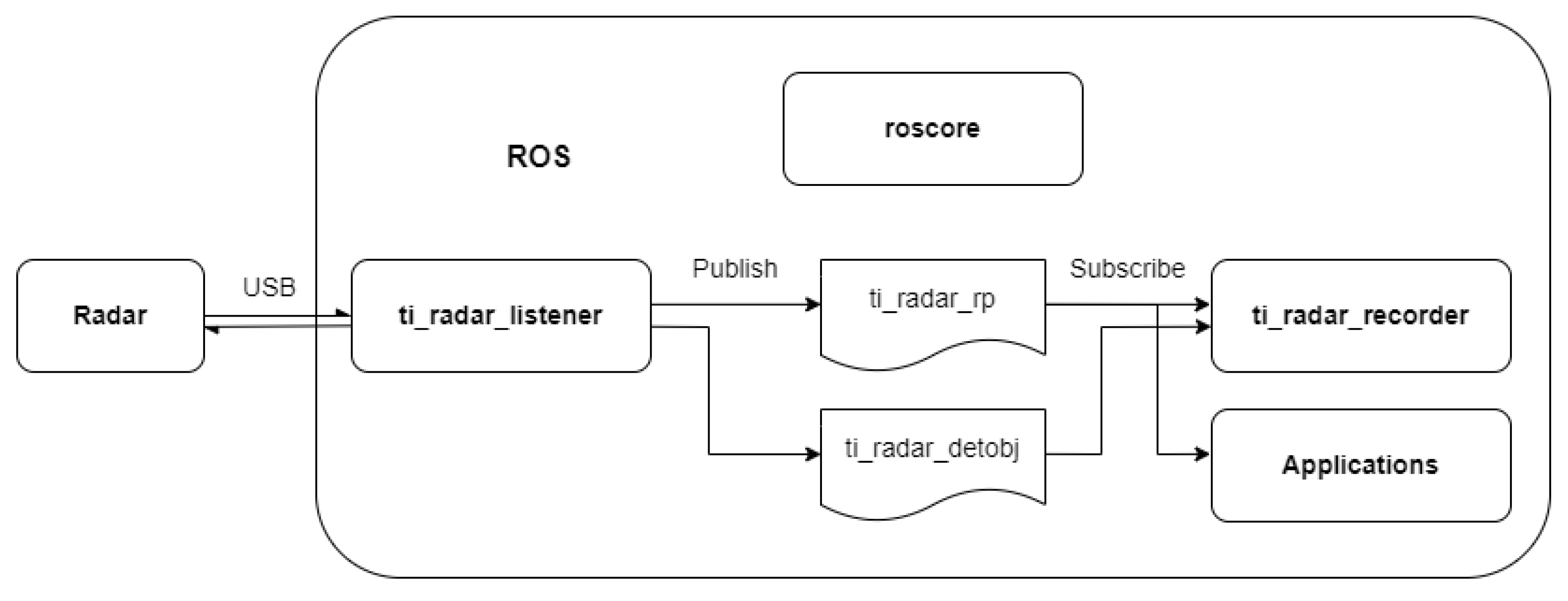
The software developed in this work uses ROS framework. Figure 1 shows the architecture of the proposed system which runs on the host computer. The host computer is responsible from extracting radar parameters from
- extracting radar parameters from a configuration file,
- configuring radar parameters,
- starting/stopping radar measurements,
- publishing received radar data to ROS,
- postprocessing the radar data,
- storing the data for later processing.
Figure 1.
ROS architecture on the host computer.
2.2. FMCW Radar Theory
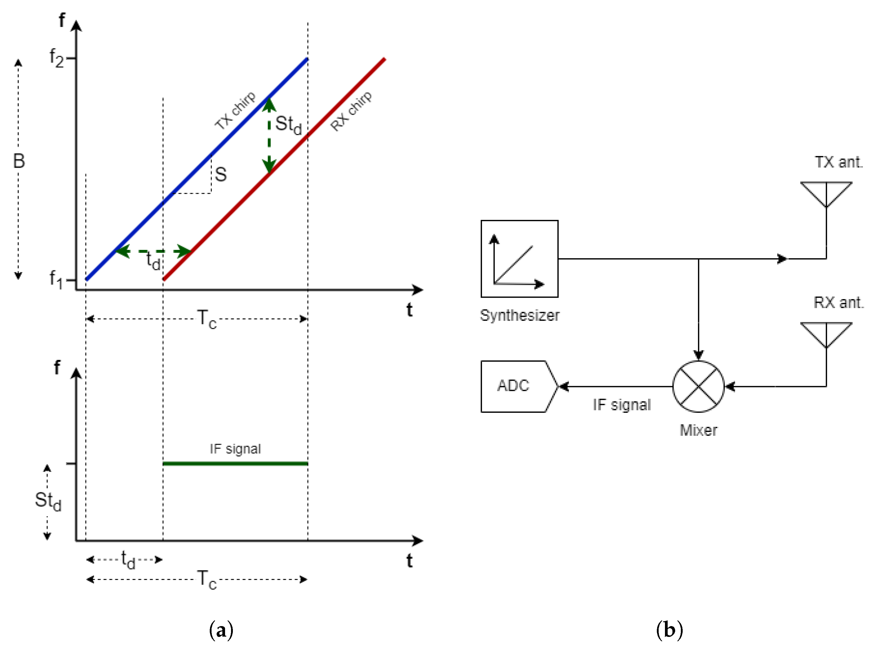
Radars transmit and receive radio waves. They are designed to detect at least one of the properties among the existence, motion, distance, velocity, angular position of the targets of interest, depending on the technique they use. For example, CW radars cannot detect static objects as their operation relies on Doppler shifts caused by their relative velocity. They cannot detect distance to an object since they have no way of knowing the time of flight. Conventional pulse radars determine the time delay between outgoing and incoming pulses to determine the target range. FMCW radars modulate the frequency of the signal over time as in Figure 2a to obtain a chirp signal which enables target detection at range.
Using the time of flight of the radio waves and the speed of propagation, the distance between the target and the radar can be calculated. The time delay between the transmitted and received wave can be calculated by
where R is the range, is the time delay between transmitted wave and received radar echo and c is the speed of light. Detection of this time delay between the outgoing wave and the incoming wave requires advanced electronic equipment. The most important reason why FMCW radars have become popular in recent years is that this time delay makes it possible to detect with simpler circuits. Figure 2b shows basic building blocks of a typical FMCW radar implementation.
Figure 2.
(a) Frequency vs. time plots of transmitted and received chirps and resultant IF signal in a FMCW radar. (b) Building blocks of a simple FMCW radar.
Figure 2.
(a) Frequency vs. time plots of transmitted and received chirps and resultant IF signal in a FMCW radar. (b) Building blocks of a simple FMCW radar.
In FMCW radar, the wave emitted by the transmitter can be defined as
whereas the received wave is
where represents the highest frequency of the chirp and represents the lowest frequency, represents the pulse width or a period of the wave, and represents the delay of the received wave. The bandwidth of the system B can be defined as . Mixing the outgoing and incoming waves and then applying a low pass filter (LPF) to eliminate high frequency components, the output will become
Thus, a single tone sinusoidal is obtained at the output of FMCW radar circuitry. The frequency of this signal is proportional to which can be used to determine the range of the target. Using Equation (1) to replace , becomes
The linear relationship between the frequency of the signal and the range is also obtained as
where term is an important parameter in FMCW radar systems, showing the frequency slope, hence it is mostly expressed as S. Finally, range of an object can be determined by solving Equation (6) for R, resulting in
2.3. Postprocessing
In this section, a postprocessing algorithm to detect the altitude and received radar reflection from that distance is presented. Here, the term altitude is used in the meaning of height above ground level (HAGL). A processing step called range compensation is also proposed to overcome the difference in reflection values from varying distances.
The radar generates a 2D detection matrix by performing 2D FFT on the sampled radar signals and averaging over the virtual antennas formed by transmitter and receiver antenna pairs. Then, the range profile along the 0-Doppler bins is transmitted to the host computer. A flow chart showing the postprocessing steps of the range profiles is given in Figure 3.
Range profiles are formed by range bins, which are obtained by the FFT results of the FMCW radar output. The relation between the range value and the frequency is described before in Equation (7). Each range bin provides information about the level of reflections obtained from a range interval, hence the envelope of the range profile can be examined to detect the existence and the distance of an object, e.g., the ground or a metal object. A reflection threshold value for the ground can be determined by
where is the reflection value in at the ith range bin, N is the number of range bins in a radar frame, or FFT length, is an arbitrary ground threshold value that is determined according to the surroundings of the radar and kept constant for all radar frames in a measurement. The method used here is similar to the adaptive threshold of constant false alarm rate (CFAR) detection in that term in Equation (8) is chosen to keep the false alarm rate constant for an object whereas the second term on the right side of the equation forms the adaptive part of the threshold value.
Figure 3.
Flow chart of the postprocessing of range profiles.

The entire range profile may not be useful for a radar measurement. For example, the first few range bins inevitably contain near-DC terms of the IF signal. Effects such as antenna coupling can also be observed at short ranges. The reflection values at these near-DC may dominate the values at the remaining bins. Moreover, since the furthermost range bins correspond to frequencies around the Nyquist rate, the information in these bins are less meaningful. Therefore, radar systems use a minimum and a maximum distance that useful information can be obtained. The marginal indices for the range bins of interest can be found as
where is the range interval of a range bin, and are, respectively, arbitrary minimum and maximum range values of interest, and are nearest index numbers which correspond to and , respectively.
Examining the envelope of the range profile after the ground threshold and marginal indices are found, the index of the range bin that the ground reflections fall into, , can be obtained by
Using this index, the altitude can be found by
and the ground reflection value in the vicinity of the altitude can be chosen as
The reasons for the small interval in Equation (12) are that in a discrete Fourier transform (DFT), phasors are shared between successive range bins since the frequency values are discretized, and that the reflections from an object can fall into multiple range bins.
To detect the existence of an object that is more reflective than the ground, another threshold value for that object needs to be determined. For this, a calibration measurement can be done before the actual mission so that a mean value of the ground reflection from the desired altitude is obtained, and the reflection value obtained for each observation in a measurement can be compared to the object threshold for object detection. The object threshold value can be found by
where is the ground reflection value obtained from the ith observation, M is the number of the observations used for calibration, is an arbitrary object threshold value that depends on the reflective properties of the object, which can be determined by practical results.
The altitude and reflection detection methods described above use the range profiles as they are formed by the radar sensor. This methods are useful assuming the altitude of the drone is greater than a certain value and does not change too much. The reflections coming from an object may be lost within the clutter at low altitudes due to the aforementioned reasons that cause near-DC terms to be high. Another such reason is the free-space path loss (FSPL). It is the loss that is experienced by a signal as it propagates. The radar range equation takes this phenomena into account. Received power is proportional to , according to the radar range equation. This means that signals are attenuated heavily with the distance. Signal amplitudes are high at short ranges, and amplitudes obtained from different ranges vary greatly, making comparisons difficult. Therefore, if the change in the drone altitude is relatively big during a flight, the reflection values would differ greatly. The FSPL may be compensated by some analog filters but the radar sensor used in this work does not perform such a filtering.
Each range bin is affected differently by a factor that affects the amplitude of the radar output signal depending on the frequency since the frequencies are transformed to ranges in a FMCW radar. One such factor is antenna gain. Antenna gain changes with frequency. Radar cross-section also depends on the frequency. Furthermore, the amount of reflections that reach the effective aperture of the antenna also change with the distance to an object. Although their effect is slight except FSPL, each of these concepts influence the amplitude of the IF signal.
A processing step that may compensate for these affects would enhance the performance of the altitude and reflection detection methods. A method called range compensation is proposed to achieve this, which can be formulated as
where and are the reflection values at the ith range bin before and after the range compensation, respectively, is the range value of the ith range bin, k is an arbitrary positive real number, the value of which can be determined practically. Since the reflection values are expressed in dB, Equation (14) actually multiplies each reflection value with a constant power of the corresponding range value. Note that after the calibration for determining the object threshold level, each observation can be processed separately with proposed methods, enabling navigation aid applications.
3. Experimental Results
A field experiment is conducted at Ucaksavar Stadium of Bogazici University. Top view of the flight mission is illustrated in Figure 4. Each circle indicates a waypoint whereas diamonds indicate waypoints with a radar target placed below. The horizontal distances between the waypoints are 13.5 m and 6 m in x- and y- directions in Cartesian coordinate system, respectively. The drone is planned to hold its position for 10 s at when it arrives the waypoints with dark grey markers, and 5 s at those with light grey markers. The wait times are set to ease time-stamping the experiment using the video record as well as interpreting radar measurements. Uncolored waypoint markers indicate that the drone will not stop but pass through those points. In addition, the waypoints named T, L, D indicate takeoff, landing, dummy points, respectively. Dummy point is added to ensure the orientation of the drone before the actual mission starts. The height of the waypoints are chosen as 7 m considering the accuracy of GPS and barometer sensors.
The radar parameters need to be determined according to the needs of the experiment. Two identical stainless steel square-sided trihedral corner reflectors with edge length of 25 cm are used in the field experiment. Radar configuration is done by observing one of these targets placed at 7 m distance from the radar. Then, the radar is mounted on the UAV so that it is downward-looking. Some of the useful configuration parameters are listed in Table 1. Radar system budget is given in Table 2 for 7 m range and the corner reflector used in the experiment.
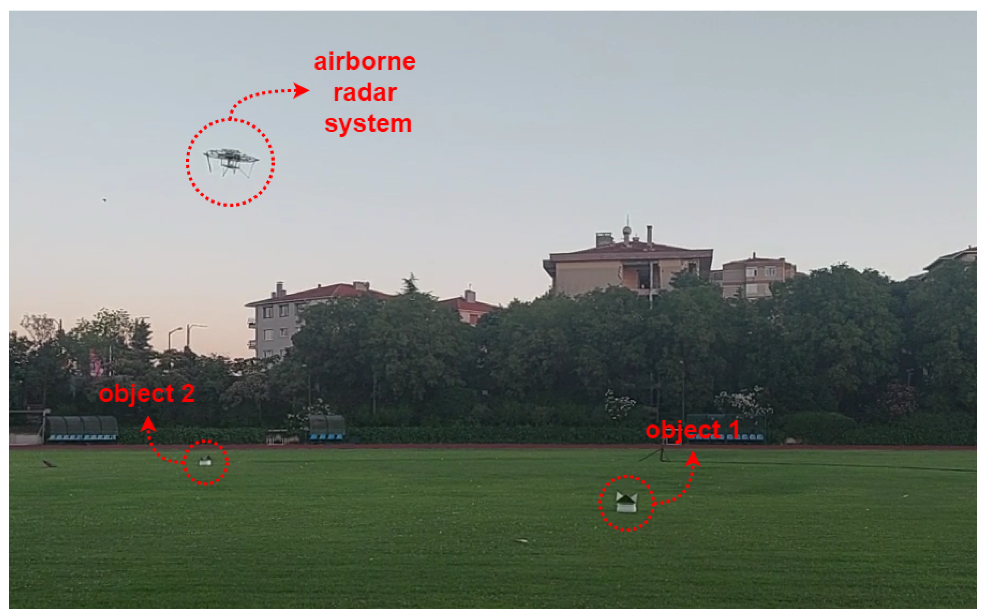
A flight summary is given in Table 3. Radar system, including cables and the battery, weighs less than 1.2 kg. The altitude estimation of the radar is appended at the end of the table. In addition, there are two time periods, one after the takeoff and one before the landing, that are collectively represented as preparation duration. Other duration items are self-explanatory. Figure 5 shows the airborne radar system while it is flying towards an object during the experiment.
3.1. Results and Discussion
In this section, results of the field experiment are presented and discussed. Figure 6 shows the effect of range compensation method on a range profile. Figure 7 compares the radar measurements before and after the application of range compensation. Figure 8 shows the results obtained by using proposed postprocessing method with and without range compensation.
Range profiles recorded throughout the experiment are plotted against time without postprocessing in Figure 7a. There are two distinct time periods which are meaningful: around 0–80 s and around 140–360 s. The former is the time period that the drone is carried manually to the takeoff point in the measurement site. Then, it is put on the ground until the mission is started. The latter time period corresponds to the flight.
The altitude of the drone during the flight can be tracked on Figure 7a. The reflections coming from the radar target around waypoint 15, which is marked as object 2 in Figure 5, can be seen between 297–308 s around 6–7 m, and their harmonic signals around 12–14 m. The altitude change within this interval is also clearly captured in the video recording. The radar target around waypoint 5, which is marked as object 1 in Figure 5, cannot be seen here clearly as it is swiftly flown over. However, it will be detected later.
The altitude and reflection detection methods described in Section 2.3 are applied to the range profiles. The results are shown in Figure 8a. The minimum altitude value used in the postprocessing of this figure is 0.80 m. The altitude against time plot resembles the altitude that can be tracked on Figure 7a, except at a few points around 320 s where the altitude could not be detected, hence the plot goes to 0. Another such case is seen during the takeoff around 150 s where the altitude detection starts, then it is disrupted and goes to 0, and continues afterwards. The reflection values detected during the flight are mostly around the same level as they are coming from ground level. Reflections from object 2 are clearly visible. In addition, there is a spike around 210 s, which indicates the reflections coming from object 1 as the drone was between waypoint 4 and waypoint 6 at that time according the video recording. The altitude and reflection values are also detected for the period in which drone is carried manually.
The reflection magnitudes at ranges below 1 m seem to be high in Figure 8a. When minimum altitude value for detection is set to lower values, the altitude detection deteriorates since the near-DC terms start to become dominant as it is described in Section 2.3. Figure 8b shows such a case where the minimum altitude is set to be 0.20 m. Moreover, the magnitudes of ground reflections obtained from approximate altitudes of 1 m and 7 m differ by around 7 dB according to the Figure 8a.
The range compensation method described in Equation (14) is applied to the range profiles in order to overcome the issues described above. Figure 6 shows the range profile obtained at 300.0 s, both before and after range compensation. At this time instant, airborne radar system is at waypoint 15, under which object 2 is placed. A ground threshold level is also marked for both cases. It is clear that the minimum altitude value used in detection steps enhances with range compensation as the range bins at very low altitudes are suppressed. It is worth noting that the value of k in Equation (14) that gave the best results among several values is found to be 10, and an extensive grid search was not necessary since the obtained results are good enough.
Figure 6.
A range profile obtained at waypoint 15, during which the radar observes an object, (a) before and (b) after range compensation.
Figure 6.
A range profile obtained at waypoint 15, during which the radar observes an object, (a) before and (b) after range compensation.

Figure 7.
Range profile against time for the entire measurement (a) without and (b) with range compensation.
Figure 7.
Range profile against time for the entire measurement (a) without and (b) with range compensation.
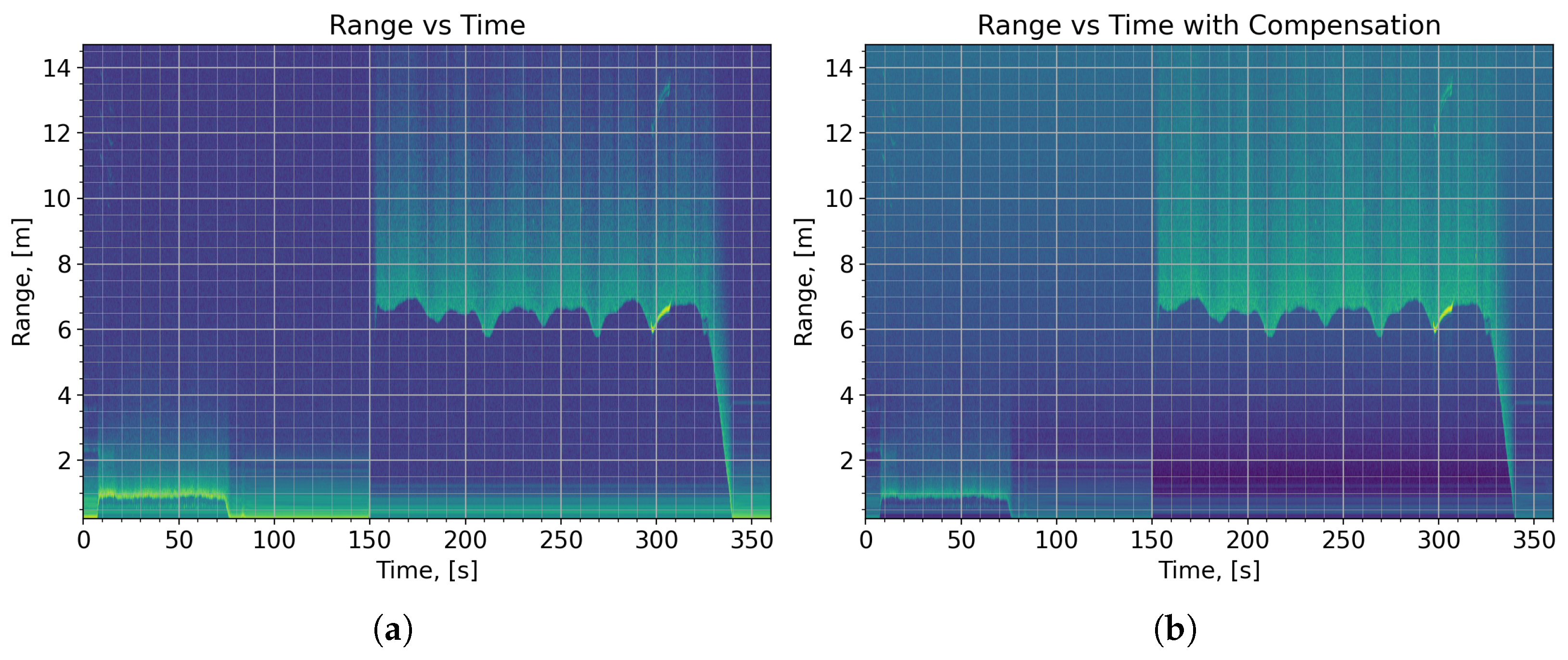
Figure 7 shows the range profiles, before and after range compensation. The plot becomes much clearer at short ranges after range compensation than it was before. Figure 8c shows the detected altitude and reflections after range compensation. The minimum altitude value is set to 0.20 m.
The results in Figure 8c are way better than those in Figure 8b, which uses the same minimum altitude value without performing range compensation. The altitude plot is similar to that in Figure 8a, except the disruption around 320 s no longer exists. The landing altitudes are almost completely observed as the distance between the radar and the bottom of the drone is 0.14 m. Lifting and lowering of the drone during its transport before the mission are started to be observed. Even the tilting of the drone to check the LEDs of the radar after it is put on the ground is seen as a small spike around 80 s. Level of ground reflection magnitudes obtained from the grassy soil at different altitudes became approximately equal, namely 45 dB. Furthermore, the threshold level for the objects became more apparent. Reflections coming from both metal objects are seemed to be at least 6 dB higher than those coming from the soil in this experiment.
Figure 8.
Detected altitude and reflection against time (a) without range compensation and 0.80 m minimum altitude, (b) without range compensation and 0.2 m minimum altitude, (c) with range compensation and 0.20 m minimum altitude.
Figure 8.
Detected altitude and reflection against time (a) without range compensation and 0.80 m minimum altitude, (b) without range compensation and 0.2 m minimum altitude, (c) with range compensation and 0.20 m minimum altitude.

In Figure 8c, object 1 is observed at 209 s for 0.3 s with 52 dB reflection level whereas object 2 is observed between 297 s and 308 s with reflection level between 53 dB and 59 dB. The signal levels differ for two objects, although the objects are identical. This may stem from several reasons. The accuracy of position sensors used in drone navigation is relatively low. For instance, the drone was supposed to hold its position at waypoint 15; however, it is actually observed during the measurement that the altitude of the drone noticeably increased, which can also be seen between 299 s and 307 s in Figure 8c, and that the horizontal position of the drone showed some deviation. A drift in horizontal position of the drone would affect the angle of arrival, and hence lower the RCS of the object. Object 2 reflections differ in time due to this phenomenon. However, since it is observed for some time, better angle of arrival values occur and higher reflection levels are obtained as well. Object 1 reflection level is 0.5 dB and 7 dB lower than minimum and maximum reflection levels of object 2, respectively. Again, during the measurement, the drone is observed to follow the flight path between waypoint 4 and 6 with some horizontal deviation, affecting object 1 reflection level. Additionally, the drone and radar would have an angle of inclination while traveling horizontally, therefore lowering RCS. Object 1 reflections also suffer from this phenomenon. Nevertheless, both metal objects were successfully distinguished from grassy soil by comparing radar reflection magnitude with an object threshold value.
The results show that proposed FMCW-UAV system and postprocessing method work well together. The accuracy of the altitude measurement is critical for the navigation of the drone. It is explained above that drone altitude drifted noticeably while it was supposed to remain constant. This setup uses the altitude information obtained from GPS and barometer. With range resolution as good as a few centimeters, 77-GHz FMCW radar will report better altitude measurements. In addition, since radars are slightly affected by the weather conditions and they can work at night as well, a radar altimeter is advantageous over optical solutions such as lidars. Furthermore, with the use of a radar, reflective property of the target material is also obtained.
One final remark is that the altitudes of the landing period are observed better than those of takeoff period. This results from the fact that the radar is programmed to transfer range profiles in the 0-Doppler bins. The altitude change in both periods are around 6.5 m while the takeoff and landing durations are 6 s and 13 s, respectively, according to Table 3. The radial velocity of the ground during the takeoff and landing becomes 0.50 m/s and 1.08 m/s, respectively. Since the velocity resolution is 0.62 m/s, which is given in Table 1, the ground reflections during the former period falls into the 0-Doppler bin while the latter does not. This can also be seen in Figure 7 where the track of ground reflections become almost indistinguishable in both cases during takeoff.
3.2. Future Work
Proposed drone system can be equipped with RTK sensor to obtain more accurate positioning information so that more comprehensive experimental flights can be realized. Accurate position information also enables advanced applications such as SAR imaging, which can be performed using a backprojection algorithm. Such an algorithm can be implemented on the processing platform of the radar system as its GPU cores allow parallel processing and speed up the generation of a final image.
Other types of sensors which are capable of detecting distance such as lidars can also be employed on the system so that the measurement results obtained with the radar can be compared to the output of these sensors. Currently, the radar is able to state an altitude value, which is measured with respect to the ground level. Using other sensors to measure the orientation and the altitude with respect to the mean sea level of the drone with a similar precision to the radar can allow applications such as terrain mapping.
The radar system can report an altitude value in ROS environment and, theoretically, a flight controller can use this information. This step is not realized in this work as it is a compelling task by itself. An open-source autopilot software is used in this work as it is. A new autopilot software that can take the altitude measurement obtained with the radar into account for navigating the drone can be developed.
4. Conclusions
A radar-equipped drone system, together with radar postprocessing steps, are proposed to be used in drone positioning applications. The results of the field experiment done at the Ucaksavar Stadium of Bogazici University show that proposed FMCW radar system and postprocessing methods can be used to detect the altitude above ground level and the magnitude of the ground reflections. To overcome the issue of variation in ground reflection values with the radar range, a range compensation method is proposed, which resembles path loss compensation. Ground reflection values obtained from different ranges become similar with this solution. Minimum detectable altitude is also improved. The objects placed on the ground were successfully distinguished from the ground in the experiment.
The success on the field test verifies that proposed radar system can be used in UAV positioning applications. The landing time period in Figure 8c clearly shows that one such example is landing aid. The radar system can provide information that can be useful for navigation of a UAV by making use of the described postprocessing steps which can be applied near real-time onboard. This is an important advancement since most of the recent airborne radar systems used onboard small UAVs in the literature either store or transfer the radar data to perform postprocessing on the ground station, without using the radar data in navigation. These recently developing systems do not involve sufficient computational resources for onboard postprocessing. Historically, such radar systems were only usable on heavy airborne vehicles due to their complicated circuitry, hence their weight. Proposed radar system is able to provide radar reflection information as well, which may help collecting information about material properties. Furthermore, the onboard processing platform can provide resources for additional applications such as radar imaging, SAR, and more advanced object detection algorithms.
Author Contributions
Conceptualization, Ö.O.B., B.O. and A.Ö.; methodology, Ö.O.B., B.O. and A.Ö.; software, Ö.O.B.; validation, Ö.O.B. and A.Ö.; formal analysis, Ö.O.B. and A.Ö.; investigation, Ö.O.B.; resources, A.Ö.; data curation, Ö.O.B.; writing—original draft preparation, Ö.O.B., B.O. and A.Ö.; writing—review and editing, Ö.O.B. and A.Ö.; visualization, Ö.O.B.; supervision, A.Ö.; project administration, Ö.O.B., B.O. and A.Ö.; funding acquisition, A.Ö. All authors have read and agreed to the published version of the manuscript.
Funding
This work was partially supported by the Scientific and Technological Research Council of Turkey under project number 119E203, and Boğaziçi University research fund grant number 19002 and grant number 22A2ADP1.
Data Availability Statement
The datasets generated and/or analyzed during this study is available from the corresponding author upon reasonable request.
Acknowledgments
The authors of this work would like to acknowledge the contribution of the members of Bogazici University Microwave Radar and Communication Laboratory (MiRaCL) in the design, montage and aviating of the drone during the airborne measurement.
Conflicts of Interest
The authors declare no conflict of interest.
References
- Chakrabarty, A.; Morris, R.; Bouyssounouse, X.; Hunt, R. Autonomous Indoor Object Tracking with the Parrot AR.Drone. In Proceedings of the International Conference on Unmanned Aircraft Systems (ICUAS), Arlington, VA, USA, 7–10 June 2016; pp. 25–30. [Google Scholar]
- Ma’Sum, M.A.; Arrofi, M.K.; Jati, G.; Arifin, F.; Kurniawan, M.N.; Mursanto, P.; Jatmiko, W. Simulation of Intelligent Unmanned Aerial Vehicle (UAV) for Military Surveillance. In Proceedings of the International Conference on Advanced Computer Science and Information Systems (ICACSIS), Sanur Bali, Indonesia, 28–29 September 2013; pp. 161–166. [Google Scholar]
- Dong, J.; Ota, K.; Dong, M. UAV-based Real-Time Survivor Detection System in Post-Disaster Search and Rescue Operations. IEEE J. Miniaturization Air Space Syst. 2021, 2, 209–219. [Google Scholar] [CrossRef]
- Georgiev, G.D.; Hristov, G.; Zahariev, P.; Kinaneva, D. Forest Monitoring System for Early Fire Detection Based on Convolutional Neural Network and UAV imagery. In Proceedings of the 28th National Conference with International Participation (TELECOM), Sofia, Bulgaria, 29–30 October 2020; pp. 57–60. [Google Scholar]
- Theodorakopoulos, P.; Lacroix, S. A Strategy for Tracking a Ground Target with a UAV. In Proceedings of the IEEE/RSJ International Conference on Intelligent Robots and Systems, Nice, France, 22–26 September 2008; pp. 1254–1259. [Google Scholar]
- Everaerts, J. The Use of Unmanned Aerial Vehicles (UAVs) for Remote Sensing and Mapping. Int. Arch. Photogramm. Remote. Sens. Spat. Inf. Sci. 2008, 37, 1187–1192. [Google Scholar]
- Salvo, G.; Caruso, L.; Scordo, A. Urban Traffic Analysis through an UAV. Procedia-Soc. Behav. Sci. 2014, 111, 1083–1091. [Google Scholar] [CrossRef] [Green Version]
- Stehr, N.J. Drones: The Newest Technology for Precision Agriculture. Nat. Sci. Educ. 2015, 44, 89–91. [Google Scholar] [CrossRef]
- Bhardwaj, A.; Sam, L.; Martín-Torres, F.J.; Kumar, R. UAVs as Remote Sensing Platform in Glaciology: Present Applications and Future Prospects. Remote Sens. Environ. 2016, 175, 196–204. [Google Scholar] [CrossRef]
- Yarlequé, M.; Alvarez, S.; Martinez, H. FMCW GPR Radar Mounted in a Mini-UAV for Archaeological Applications: First Analytical and Measurement Results. In Proceedings of the International Conference on Electromagnetics in Advanced Applications (ICEAA), Verona, Italy, 11–15 September 2017; pp. 1646–1648. [Google Scholar]
- Garcia-Fernandez, M.; Alvarez-Lopez, Y.; Las Heras, F. Autonomous Airborne 3D SAR Imaging System for Subsurface Sensing: UWB-GPR On Board a UAV for Landmine and IED Detection. Remote Sens. 2019, 11, 2357. [Google Scholar] [CrossRef] [Green Version]
- Fernández, M.G.; López, Y.Á.; Arboleya, A.A.; Valdés, B.G.; Vaqueiro, Y.R.; Andrés, F.L.H.; García, A.P. Synthetic Aperture Radar Imaging System for Landmine Detection Using a Ground Penetrating Radar On Board a Unmanned Aerial Vehicle. IEEE Access 2018, 6, 45100–45112. [Google Scholar] [CrossRef]
- García-Fernández, M.; López, Y.Á.; Andrés, F.L.H. Airborne Multi-Channel Ground Penetrating Radar for Improvised Explosive Devices and Landmine Detection. IEEE Access 2020, 8, 165927–165943. [Google Scholar] [CrossRef]
- Colorado, J.; Perez, M.; Mondragon, I.; Mendez, D.; Parra, C.; Devia, C.; Martinez-Moritz, J.; Neira, L. An Integrated Aerial System for Landmine Detection: SDR-based Ground Penetrating Radar Onboard an Autonomous Drone. Adv. Robot. 2017, 31, 791–808. [Google Scholar] [CrossRef]
- Burr, R.; Schartel, M.; Schmidt, P.; Mayer, W.; Walter, T.; Waldschmidt, C. Design and Implementation of a FMCW GPR for UAV-based Mine Detection. In Proceedings of the IEEE MTT-S International Conference on Microwaves for Intelligent Mobility (ICMIM), Munich, Germany, 15–17 April 2018; pp. 1–4. [Google Scholar]
- Burr, R.; Schartel, M.; Mayer, W.; Walter, T.; Waldschmidt, C. UAV-based Polarimetric Synthetic Aperture Radar for Mine Detection. In Proceedings of the IGARSS IEEE International Geoscience and Remote Sensing Symposium, Yokohama, Japan, 28 July–2 August 2019; pp. 9208–9211. [Google Scholar]
- Schreiber, E.; Heinzel, A.; Peichl, M.; Engel, M.; Wiesbeck, W. Advanced Buried Object Detection by Multichannel, UAV/Drone Carried Synthetic Aperture Radar. In Proceedings of the 13th European Conference on Antennas and Propagation (EuCAP), Krakow, Poland, 31 March–5 April 2019; pp. 1–5. [Google Scholar]
- Ham, Y.; Han, K.K.; Lin, J.J.; Golparvar-Fard, M. Visual Monitoring of Civil Infrastructure Systems via Camera-Equipped Unmanned Aerial Vehicles (UAVs): A Review of Related Works. Vis. Eng. 2016, 4, 1–8. [Google Scholar] [CrossRef] [Green Version]
- Kaniewski, P.; Leśnik, C.; Susek, W.; Serafin, P. Airborne Radar Terrain Imaging System. In Proceedings of the 16th International Radar Symposium (IRS), Dresden, Germany, 24–26 June 2015; pp. 248–253. [Google Scholar]
- Ye, E.; Shaker, G.; Melek, W. Lightweight Low-Cost UAV Radar Terrain Mapping. In Proceedings of the 13th European Conference on Antennas and Propagation (EuCAP), Krakow, Poland, 31 March–5 April 2019; pp. 1–5. [Google Scholar]
- Li, C.J.; Ling, H. High-Resolution, Downward-Looking Radar Imaging Using a Small Consumer Drone. In Proceedings of the IEEE International Symposium on Antennas and Propagation (APSURSI), Fajardo, PR, USA, 26 June–1 July 2016; pp. 2037–2038. [Google Scholar]
- Li, C.J.; Ling, H. Synthetic Aperture Radar Imaging Using a Small Consumer Drone. In Proceedings of the IEEE International Symposium on Antennas and Propagation & USNC/URSI National Radio Science Meeting, Vancouver, BC, Canada, 19–24 July 2015; pp. 685–686. [Google Scholar]
- Virone, G.; Lingua, A.M.; Piras, M.; Cina, A.; Perini, F.; Monari, J.; Paonessa, F.; Peverini, O.A.; Addamo, G.; Tascone, R. Antenna Pattern Verification System Based on a Micro Unmanned Aerial Vehicle (UAV). IEEE Antennas Wirel. Propag. Lett. 2014, 13, 169–172. [Google Scholar] [CrossRef]
- García-Fernández, M.; López, Y.Á.; Arboleya, A.; González-Valdés, B.; Rodríguez-Vaqueiro, Y.; Gómez, M.E.D.C.; Andrés, F.L.H. Antenna Diagnostics and Characterization Using Unmanned Aerial Vehicles. IEEE Access 2017, 5, 23563–23575. [Google Scholar] [CrossRef]
- González-Jorge, H.; Martínez-Sánchez, J.; Bueno, M.; Arias, P. Unmanned Aerial Systems for Civil Applications: A Review. Drones 2017, 1, 2. [Google Scholar] [CrossRef] [Green Version]
- Suherman, S.; Putra, R.A.; Pinem, M. Ultrasonic Sensor Assessment for Obstacle Avoidance in Quadcopter-based Drone System. In Proceedings of the 3rd International Conference on Mechanical, Electronics, Computer, and Industrial Technology (MECnIT), Medan, Indonesia, 25–27 June 2020; pp. 50–53. [Google Scholar]
- Peng, Z.; Mu noz-Ferreras, J.M.; Tang, Y.; Liu, C.; Gómez-García, R.; Ran, L.; Li, C. A Portable FMCW Interferometry Radar with Programmable Low-IF Architecture for Localization, ISAR Imaging, and Vital Sign Tracking. IEEE Trans. Microw. Theory Tech. 2016, 65, 1334–1344. [Google Scholar] [CrossRef]
- Lampersberger, T.; Feger, R.; Haderer, A.; Egger, C.; Friedl, M.; Stelzer, A. A 24-GHz Radar with 3D-Printed and Metallized Lightweight Antennas for UAV Applications. In Proceedings of the 15th European Radar Conference (EuRAD), Madrid, Spain, 26–28 September 2018; pp. 393–396. [Google Scholar]
- Kim, K.S.; Yoo, J.S.; Kim, J.W.; Kim, S.; Yu, J.W.; Lee, H.L. All-around beam switched antenna with dual polarization for drone communications. IEEE Trans. Antennas Propag. 2019, 68, 4930–4934. [Google Scholar] [CrossRef]
- Lee, C.U.; Noh, G.; Ahn, B.; Yu, J.W.; Lee, H.L. Tilted-beam switched array antenna for UAV mounted radar applications with 360° coverage. Electronics 2019, 8, 1240. [Google Scholar] [CrossRef] [Green Version]
- Ding, M.; Liang, X.; Tang, L.; Wen, Z.; Wang, X.; Wang, Y. Micro FMCW SAR with High Resolution for Mini UAV. In Proceedings of the International Conference on Microwave and Millimeter Wave Technology (ICMMT), Chengdu, China, 7–11 May 2018; pp. 1–3. [Google Scholar]
- Lort, M.; Aguasca, A.; Lopez-Martinez, C.; Marín, T.M. Initial Evaluation of SAR Capabilities in UAV Multicopter Platforms. IEEE J. Sel. Top. Appl. Earth Obs. Remote Sens. 2017, 11, 127–140. [Google Scholar] [CrossRef] [Green Version]
- Ding, M.L.; Ding, C.B.; Tang, L.; Wang, X.M.; Qu, J.M.; Wu, R. A W-band 3-D Integrated Mini-SAR System with High Imaging Resolution on UAV Platform. IEEE Access 2020, 8, 113601–113609. [Google Scholar] [CrossRef]
- Svedin, J.; Bernland, A.; Gustafsson, A.; Claar, E.; Luong, J. Small UAV-based SAR System Using Low-Cost Radar, Position, and Attitude Sensors with Onboard Imaging Capability. Int. J. Microw. Wirel. Technol. 2021, 13, 602–613. [Google Scholar] [CrossRef]
- Yan, J.; Peng, Z.; Hong, H.; Zhu, X.; Lu, Q.; Ren, B.; Li, C. Indoor Range-Direction-Movement SAR for Drone-based Radar Systems. In Proceedings of the IEEE Asia Pacific Microwave Conference (APMC), Kuala Lumpur, Malaysia, 13–16 November 2017; pp. 1290–1293. [Google Scholar]
- Weib, M.; Ender, J. A 3D imaging radar for small unmanned airplanes-ARTINO. In Proceedings of the European Radar Conference, Paris, France, 3–4 October 2005; pp. 209–212. [Google Scholar]
- Noviello, C.; Gennarelli, G.; Esposito, G.; Ludeno, G.; Fasano, G.; Capozzoli, L.; Soldovieri, F.; Catapano, I. An overview on down-looking UAV-based GPR systems. Remote Sens. 2022, 14, 3245. [Google Scholar] [CrossRef]
- Meta, A.; Hoogeboom, P.; Ligthart, L.P. Signal Processing for FMCW SAR. IEEE Trans. Geosci. Remote Sens. 2007, 45, 3519–3532. [Google Scholar] [CrossRef]
- Patole, S.M.; Torlak, M.; Wang, D.; Ali, M. Automotive Radars: A Review of Signal Processing Techniques. IEEE Signal Process. Mag. 2017, 34, 22–35. [Google Scholar] [CrossRef]
- Rao, S.; Ahmad, A.; Roh, J.C.; Bharadwaj, S. 77GHz Single Chip Radar Sensor Enables Automotive Body and Chassis Applications; Texas Instruments: Dallas, TX, USA, 2017. [Google Scholar]
- Wang, F.K.; Horng, T.S.; Peng, K.C.; Jau, J.K.; Li, J.Y.; Chen, C.C. Detection of Concealed Individuals Based on Their Vital Signs by Using a See-Through-Wall Imaging System with a Self-Injection-Locked Radar. IEEE Trans. Microw. Theory Tech. 2012, 61, 696–704. [Google Scholar] [CrossRef] [Green Version]
- Wang, F.K.; Horng, T.S.; Peng, K.C.; Jau, J.K.; Li, J.Y.; Chen, C.C. Seeing Through Walls with a Self-Injection-Locked Radar to Detect Hidden People. In Proceedings of the IEEE/MTT-S International Microwave Symposium Digest, Montreal, QC, Canada, 17–22 June 2012; pp. 1–3. [Google Scholar]
- Gunn, G.E.; Duguay, C.R.; Atwood, D.K.; King, J.; Toose, P. Observing Scattering Mechanisms of Bubbled Freshwater Lake Ice Using Polarimetric RADARSAT-2 (C-Band) and UW-Scat (X-and Ku-Bands). IEEE Trans. Geosci. Remote Sens. 2018, 56, 2887–2903. [Google Scholar] [CrossRef]
- Wang, H.; Jiang, M.; Zheng, S. Airborne Ka FMCW MiSAR System and Real Data Processing. In Proceedings of the 17th International Radar Symposium (IRS), Krakow, Poland, 10–12 May 2016; pp. 1–5. [Google Scholar]
- Park, J.; Park, S.; Kim, D.H.; Park, S.O. Leakage mitigation in heterodyne FMCW radar for small drone detection with stationary point concentration technique. IEEE Trans. Microw. Theory Tech. 2019, 67, 1221–1232. [Google Scholar] [CrossRef] [Green Version]
- Engelbertz, S.; Krebs, C.; Küter, A.; Herschel, R.; Geschke, R.; Nüßler, D. 60 GHz low phase noise radar front-end design for the detection of micro drones. In Proceedings of the 2019 16th European Radar Conference (EuRAD), Paris, France, 2–4 October 2019; pp. 25–28. [Google Scholar]
- Ramasubramanian, K. Using a Complex-Baseband Architecture in FMCW Radar Systems; Texas Instruments: Dallas, TX, USA, 2017. [Google Scholar]
Figure 4.
Top view of the flight mission.

Figure 5.
The airborne radar system while it is flying towards an object during the experiment.

Table 1.
Summary of FMCW radar configuration parameters.
| Radar Parameter | Value |
|---|---|
| Radar Configuration | MIMO (3 TX/4 RX) |
| Modulation Scheme | Sawtooth |
| Start Frequency | 77 GHz |
| Useful Bandwidth | 3.4 GHz |
| Frame Period | 100 ms |
| Range Resolution | 0.044 m |
| Max. Unambiguous Range | 14.68 m |
| Velocity Resolution | 0.62 m/s |
| Max. Radial Velocity | 4.94 m/s |
| Samples per Chirp | 416 |
| Num. of Range Bins | 512 |
| Range Bin Width | 0.036 m |
Table 2.
Radar system budget.
| Radar Budget Term | Symbol | Value |
|---|---|---|
| Transmit Power | +12 dBm | |
| TX Antenna Gain | +10.5 dBi | |
| RCS | +39.9 dBsm | |
| RX Antenna Gain | +10.5 dBi | |
| Range | R | 7 m |
| Wavelength | 3.9 mm | |
| Received Power | −42.1 dBm |
Table 3.
Summary of the measurement flight.
| Parameter | Value |
|---|---|
| Total Weight | 4.7 kg |
| Radar System Weight | ≤1.2 kg |
| Total Horizontal Distance | ∼178 m |
| Horizontal Velocity | ∼2.2 m/s |
| Takeoff Duration | 6 s |
| Preparation Duration | 10 s |
| Travel Duration | 82 s |
| Position Hold Duration | 80 s |
| Landing Duration | 13 s |
| Total Flight Duration | 191 s |
| Target Altitude | 7.0 m |
| Radar-Estimated Altitude | ∼5.7–7.2 m |
Disclaimer/Publisher’s Note: The statements, opinions and data contained in all publications are solely those of the individual author(s) and contributor(s) and not of MDPI and/or the editor(s). MDPI and/or the editor(s) disclaim responsibility for any injury to people or property resulting from any ideas, methods, instructions or products referred to in the content. |
© 2023 by the authors. Licensee MDPI, Basel, Switzerland. This article is an open access article distributed under the terms and conditions of the Creative Commons Attribution (CC BY) license (https://creativecommons.org/licenses/by/4.0/).
Share and Cite
MDPI and ACS Style
Başpınar, Ö.O.; Omuz, B.; Öncü, A. Detection of the Altitude and On-the-Ground Objects Using 77-GHz FMCW Radar Onboard Small Drones. Drones 2023, 7, 86. https://doi.org/10.3390/drones7020086
AMA Style
Başpınar ÖO, Omuz B, Öncü A. Detection of the Altitude and On-the-Ground Objects Using 77-GHz FMCW Radar Onboard Small Drones. Drones. 2023; 7(2):86. https://doi.org/10.3390/drones7020086
Chicago/Turabian StyleBaşpınar, Ömer Oğuzhan, Berk Omuz, and Ahmet Öncü. 2023. "Detection of the Altitude and On-the-Ground Objects Using 77-GHz FMCW Radar Onboard Small Drones" Drones 7, no. 2: 86. https://doi.org/10.3390/drones7020086