Proceeding Paper

Method of Monitoring Cracks in a Metal Structure Based on Dual-Chip RFID Antenna Sensor †

1
School of Logistics Engineering, Wuhan University of Technology, 1178 Heping Ave, Wuhan 430063, China
2
Engineer Research Center of Logistic Technology and Equipment, Ministry of Education, Wuhan 430063, China
*
Author to whom correspondence should be addressed.
Presented at the 6th International Electronic Conference on Sensors and Applications, 15–30 November 2019; Available online: https://ecsa-6.sciforum.net/.
Proceedings 2020, 42(1), 3; https://doi.org/10.3390/ecsa-6-06553
Published: 14 November 2019

Abstract

:
The microstrip patch antenna sensor is a novel sensor used for structural health monitoring which can measure a metal structure’s crack defects in a wireless manner. However, it is difficult to identify the reflected signal from the signal of an antenna sensor. The radio-frequency identification (RFID) antenna sensor, which combines RFID technology and the microstrip patch antenna sensor, can solve the measurement problems that are difficult to the conventional wireless testing technologies. In this study, a dual-chip RFID antenna sensor was designed. The influence of the wireless testing method on the monitoring results of crack defects was investigated by tests, including the wireless tests of resonant frequency and the crack sensitivity tests. The tests results revealed that the antenna sensor had good wireless testing performance with regard to the metal structure’s crack defects. Additionally, the maximum of wireless identification distance reached 1.96 m.

1. Introduction

Fatigue failure, caused mainly by cracks, can cause significant casualties and property damage, which makes structural health monitoring (SHM) an indispensable safety measurement for ensuring the safe and reliable operation of large structures [1].
The patch antenna sensor is a novel sensor used for SHM which can measure the strain and crack of metal structures wirelessly and passively [2]. Deshmukn and Huang first applied patch antennas to the identification of fatigue cracks in metal structures [3]. Subsequently, Yi, Liu and Ke et al. [4,5,6] also investigated the crack test results of patch antennas, but the wired connection was mainly used.
When the signal of the patch antenna sensor is read wirelessly, the sensor reflection signal is not easily identified. Therefore, it is critical to eliminate the interference of the surrounding clutter signal. Yi, Huang and Yao et al. proposed the wireless testing method based on the frequency doubling principle [7], the switching circuit [8], the double horn antenna [9], the impedance switch circuit controlled by an oscillator [10] and the delay function of the microstrip line [11], respectively. However, all the antenna sensors above are externally connected to the modulation circuit, and the sensor structure and test system are relatively complex.
The RFID technology processes the reflected signal through the load modulation of the chip, which is advantageous in eliminating the interference of the background reflection signal [12]. Zhang et al. designed an RFID antenna sensor to investigate the influence of crack depth on the activation threshold of the sensor. The stability of the wireless test result was good and the resonant frequency of the sensor decreases linearly with the crack depth’s increase [13]. However, to date, domestic and overseas studies on RFID antenna sensors have been scarce, and this novel sensor is still in the exploratory and feasibility investigation stage. Thus far, crack identification has not been carried out with dual-band dual-chip RFID antenna sensors.
Therefore, combining the RFID technology and the patch antenna sensor, a dual-chip RFID antenna sensor is designed in this study. The resonant response of the sensor to cracks is analyzed using the High Frequency Structure Simulator (HFSS) software. Moreover, the crack test sensitivity experiment and the frequency response measurement of cracks under different emission powers are conducted in a wireless manner. Additionally, the wireless test results for cracks and the variation of crack test sensitivity are investigated.

2. Materials and Methods

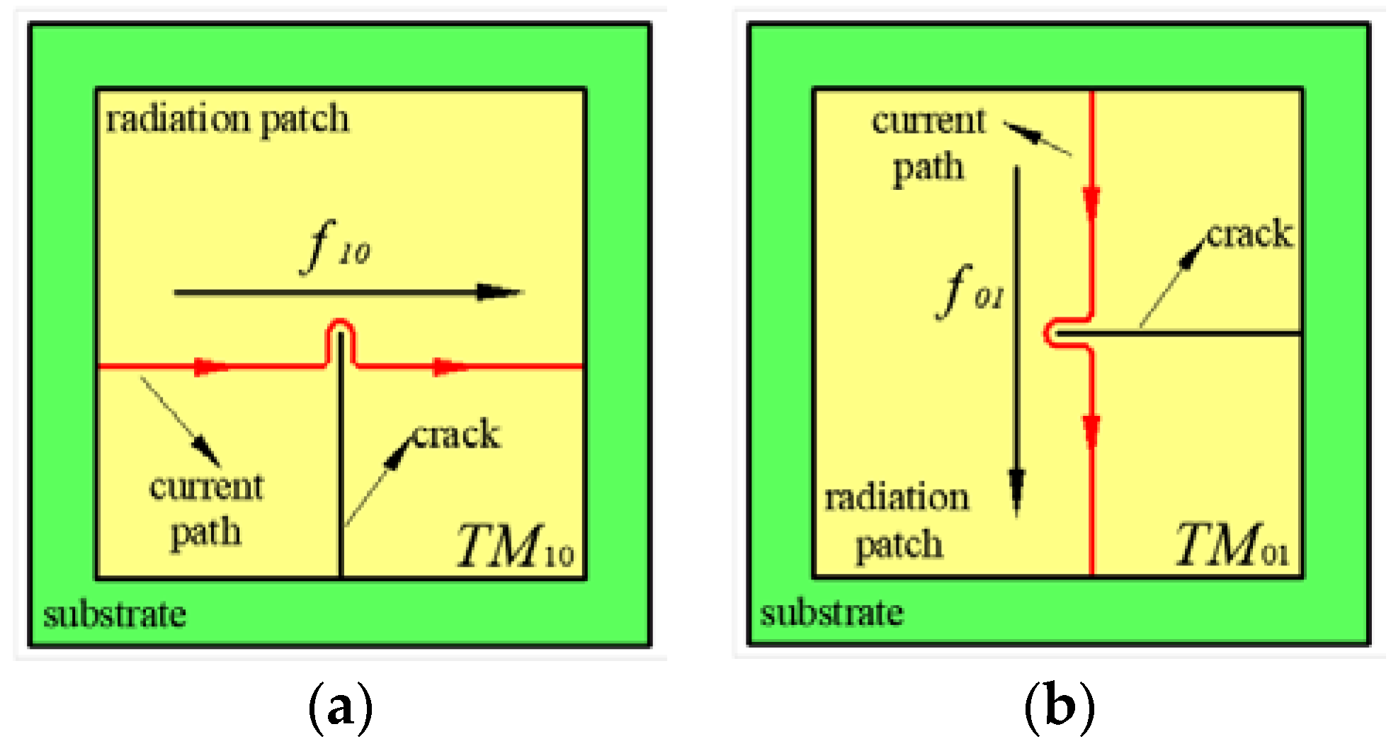
2.1. Principle of Crack Identification

The crack identification principle of the RFID antenna sensor is mainly based on the meandering technique. As shown in Figure 1, when a crack appears on the upper surface of the ground plate, the current path bypasses along the edge of the crack, which causes the current path length to increase and thereby reduces the resonant frequency of the sensor.
As shown in Figure 1a, when the crack length is perpendicular to the patch length, the current path length of the TM10 resonant mode will amplify. If the elongation of the current path is ΔL, the resonant frequency f10 of the RFID antenna sensor is expressed as Equation (1).
f 10 = c 2 ε e 1 ( L + Δ L ) + 2 Δ l
Moreover, the crack is parallel to the current path of the TM01 resonant mode and the crack width is too small to influence the current path of the TM01 resonant mode, therefore, the resonant frequency f01 does not substantially vary. Similar to the longitudinal crack, the transverse crack in Figure 1b causes the frequency f01 of the TM01 mode to decrease and has small influence on the frequency f10.

2.2. Simulations of Crack Identification

The design frequency f01 and f10 of antenna sensor are equal, therefore, the two T-type matching structures are equal in size. The solution frequency is set to the design frequency 925 MHz in HFSS. The solution method is “fast” and the sweeping range is 800–1000 MHz (Δ = 0.01 MHz). The modes TM01 and TM10 are symmetrical, and the simulation results are presented below using the TM10 mode.
The influence of artificial machining cracks and actual cracks on the experimental are equal [6], therefore, a penetrating slot with a width of 0.5 mm is introduced to simulate the crack (see Figure 1a). The slot extends from the center of the patch to the other patch edge in steps of 4 mm.

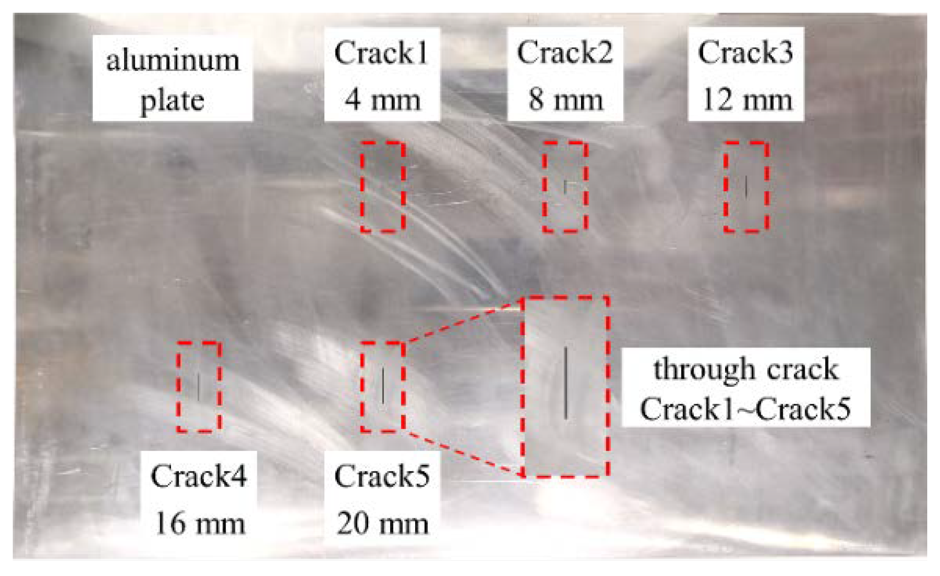
2.3. Experiments of Crack Identification

The designing process of the RFID antenna sensor is as follows: First, the length and other size parameters of the patch are calculated; then, the impedance distribution theory of the T-structure [14] is used to approximately calculate the dimensions of the T-type matching structure. Finally, the optimized design function of the HFSS is used to calculate the optimal size parameters of the antenna sensor. Figure 2 reveals the structure of the RFID antenna sensor. The design parameters of the RFID antenna sensor are listed in Table 1.
An aluminum plate made of 6061 aluminum with dimensions of 500 × 300 × 2 mm is used as the ground plate. The substrate is made of FR4 laminate with a thickness of 1 mm. As shown in Figure 3, five through cracks, Crack1–Crack5 respectively, corresponding to the crack length of 4 mm, 8 mm, 12 mm, 16 mm, and 20 mm are processed by laser. The crack width is 0.5 mm. The crack length is parallel to the width of the aluminum plate and the symmetry center lines of the adjacent cracks coincide.
The wireless test platform of RFID antenna sensor is shown in Figure 4. The constant distance variable power method and the constant power variable distance method [15] can both be used in this experiment. However, the constant power variable distance method is used, for which the method is simple in operation and low in requirements for test equipment.

3. Results

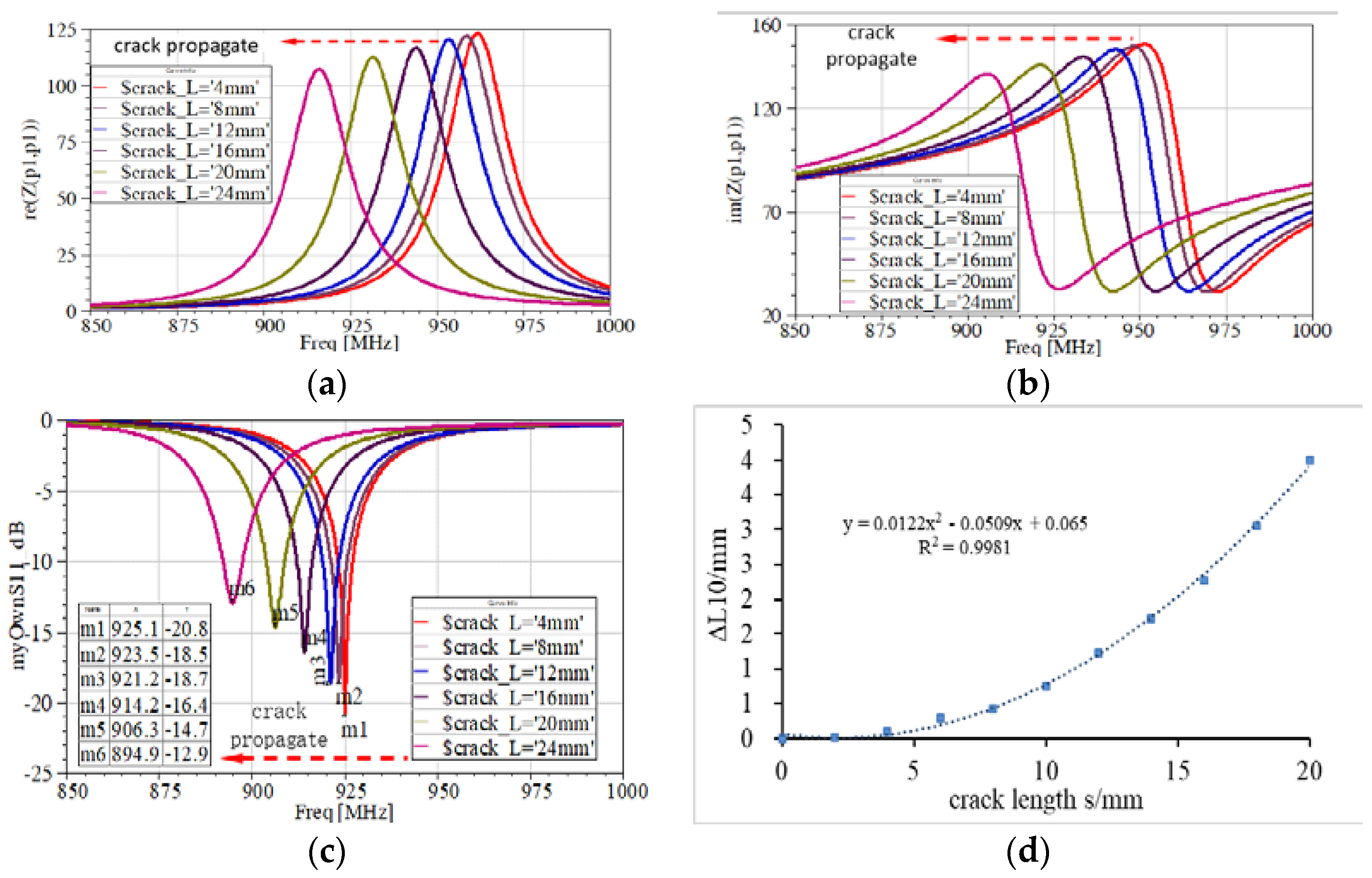
3.1. Results of Simulations

As shown in Figure 5a,b, when the crack length increases, the real part and the imaginary part of characteristic impedance decrease, the variation of them magnifies, and the peak value of the impedance curve gradually declines. As shown in Figure 5c, the curve of the antenna sensor gradually moves toward the low frequency, and the amplitude of variation gradually increases with the increasing crack length. The return loss value corresponding to the resonant frequency decreases as the crack length intensifies. The simulation results reveal that the identification distance of the antenna sensor may decrease as the crack propagates.
The curve of “resonant length variation Δ L and crack length s” is plotted in Figure 5d. As the crack length amplifies, the resonant length L10 magnifies in a parabola manner, and the siding trend becomes faster. The crack test sensitivity (resonant length elongation Δ L per 1 mm crack) of 4 mm crack length is 0.03. Moreover, the sensitivity of 24 mm length reaches 0.38. In a word, when the characteristic parameters of the antenna sensor (such as the resonant length) change with the crack elongation in an increasingly rapid manner, it is beneficial for the sensor to identify the long crack.

3.2. Results of Experiments

To investigate the wireless reading influence of the resonant frequency, the antenna sensor is attached to the crack-free region of the aluminum plate. The test is divided into four groups with transmission power of 20, 23, 25 and 27 dBm. As shown in Figure 6a, when the transmission power of the reader amplifies, the readable distance of the sensor magnifies at the same frequency. When the power intensifies to the limit, the reader’s readable distance also reaches the maximum value. When the transmission power of the reader increases to 27 dBm, the maximum identifiable distance of the sensor is 1.96 m.
As shown in Figure 6b, when the transmission power is 20 dBm and 27 dBm, the relationship between the crack length and the resonant length in TM10 mode are, respectively, Δ L 10 = 1.12 × 10 2 s 2 7.48 × 10 2 s + 0.1024 ,   R 2 = 0.997   and   Δ L 10 = 1.21 × 10 2 s 2 8.61 × 10 2 s + 7.25 × 10 2 ,   R 2 = 0.9917 . When the transmission power is 20 dBm, the resonant length of the TM01 mode is Λ L 01 = 1.1 × 10 2 s 2 2.92 × 10 2 s + 1.86 × 10 2 ,   R 2 = 0.9954 . This indicates that there is a good parabolic relationship between the crack length and the resonant length, which is in good agreement with the simulation results. The crack test sensitivity calculated from the data of Figure 6b is shown in Table 2.
Considering the test data of 20 dBm and the TM10 resonant mode as an example, when the crack is in the initial stage of propagation, the resonant length increases slowly with the crack propagation. When the crack length intensifies, the amplitude of resonant length varies. The sensitivity amplifies throughout the crack propagation process, which indicates that the antenna sensor is more sensitive to long cracks. When the crack length is 8 mm, the sensitivity is 0.15. When the crack length propagates to 20 mm, the sensitivity is 0.39, which marks a 2.6 times increase.

4. Conclusions

  • When there is no crack in the ground plate, certain differences exist amongst the measurement results of the resonant frequency of the antenna sensor under different transmission powers. However, the resonant frequency value is essentially kept within a small fluctuation range, and the accuracy of the test results can be ensured by average multiple measurements.
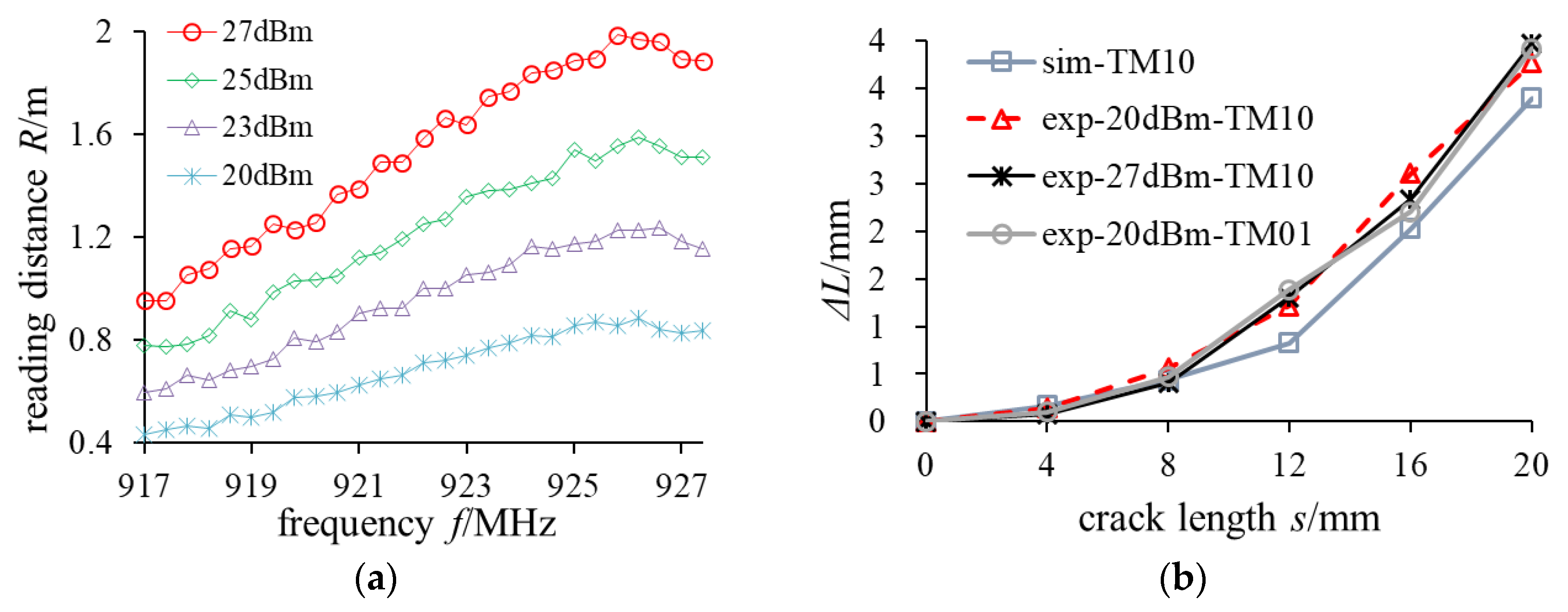
  • In the crack identification experiment, when the transmission power of the RFID reader changes, there is a slight difference in the amount of the resonant length change corresponding to the same crack length. However, this difference has no influence on the identification of crack defects. When the transmission power of the reader is constant, the crack length of the ground plate and the resonant length of the sensor maintain a good parabolic relationship.
  • The wireless test results reveal that the antenna sensor achieved good performance in wirelessly identifying cracks on a metal structure; the wireless identification distance can reach 1.96 m.

Author Contributions

Conceptualization, Z.L.; methodology, H.Y. and K.Z.; data curation, H.Y.; investigation, R.L.; writing—original draft preparation, Z.L.; writing—review and editing, Z.L.

Acknowledgments

This study was supported by the Excellent Dissertation Cultivation Funds of Wuhan University of Technology (2018-YS-071).

Conflicts of Interest

The authors declare no conflict of interest.

References

  1. Cunfu, H.; Tianting, Y.; Guorong, S.; Yan, L.; Bin, W. Design and optimization of a strain sensor based on rectangular micro-strip patch antenna. Chin. J. Sci. Instrum. 2017, 38, 361–367. [Google Scholar]
  2. Kai, Z.; Zhiping, L.; Yanfei, M.; Puping, K.; Liang, K. Plane two-dimensional strain measurement method of patch antenna sensor. Chin. J. Sci. Instrum. 2018, 39, 136–143. [Google Scholar] [CrossRef]
  3. Deshmukh, S.; Mohammad, I.; Tentzeris, M.; Wu, T.; Huang, H. Crack Detection and Monitoring Using Passive Wireless Sensor. In Proceedings of the ASME 2009 Conference on Smart Materials, Adaptive Structures and Intelligent Systems, Oxnard, CA, USA, 21–23 September 2009; pp. 511–516. [Google Scholar]
  4. Yi, X.; Cho, C.; Wang, Y.; Cook, B.; Tentzeris, M.; Leon, R. Crack Propagation Measurement Using a Battery-Free Slotted Patch Antenna Sensor. In Proceedings of the 7th European Workshop on Structural Health Monitoring, Nantes, France, 8–11 July 2014; pp. 1040–1047. [Google Scholar]
  5. Liu, Z.; Chen, K.; Li, Z.; Jiang, X. Crack Monitoring Method for an FRP-Strengthened Steel Structure Based on an Antenna Sensor. Sensors 2017, 17, 2394. [Google Scholar] [CrossRef] [PubMed]
  6. Ke, L.; Liu, Z.; Yu, H. Characterization of a Patch Antenna Sensor’s Resonant Frequency Response in Identifying the Notch-Shaped Cracks on Metal Structure. Sensors 2018, 19, 110. [Google Scholar] [CrossRef] [PubMed]
  7. Cho, C.; Yi, X.; Li, D.; Wang, Y.; Tentzeris, M.M. Passive Wireless Frequency Doubling Antenna Sensor for Strain and Crack Sensing. IEEE Sens. J. 2016, 16, 5725–5733. [Google Scholar] [CrossRef]
  8. Deshmukh, S.; Huang, H. Wireless interrogation of passive antenna sensors. Meas. Sci. Technol. 2010, 21, 035201. [Google Scholar] [CrossRef]
  9. Mohammad, I.; Huang, H. Wireless interrogation of antenna sensor to detect hidden cracks. In Proceedings of the IEEE Wireless & Microwave Technology Conference (WAMICON), Cocoa Beach, FL, USA, 15–17 April 2012. [Google Scholar]
  10. Xu, X.; Huang, H. Battery-less wireless interrogation of microstrip patch antenna for strain sensing. Smart Mater. Struct. 2012, 21, 125007. [Google Scholar] [CrossRef]
  11. Yao, J.; Tchafa, F.M.; Jain, A.; Tjuatja, S.; Huang, H. Far-Field Interrogation of Microstrip Patch Antenna for Temperature Sensing Without Electronics. IEEE Sens. J. 2016, 16, 7053–7060. [Google Scholar] [CrossRef]
  12. Tian, G.; Zhang, J.; Meng, Z. Passive Wireless RFID Sensors and Their Applications in Structural Health Monitoring. Nanjing Hangkong Hangtian Daxue Xuebao/J. Nanjing Univ. Aeronaut. Astronaut. 2017, 49, 453–460. [Google Scholar] [CrossRef]
  13. Zhang, J.; Huang, B.; Zhang, G.; Tian, G.Y. Wireless Passive Ultra High Frequency RFID Antenna Sensor for Surface Crack Monitoring and Quantitative Analysis. Sensors 2018, 18. [Google Scholar] [CrossRef] [PubMed]
  14. Marrocco, G.J.A.; IEEE, P.M. The art of UHF RFID antenna design: Impedance-matching and size-reduction techniques. IEEE Antennas Propag. Mag. 2008, 50, 66–79. [Google Scholar] [CrossRef]
  15. Kuhn, M.F.; Breier, G.P.; Dias, A.R.; Clarke, T.G. A Novel RFID-Based Strain Sensor for Wireless Structural Health Monitoring. J. Nondestruct. Eval. 2018, 37, 22. [Google Scholar] [CrossRef]
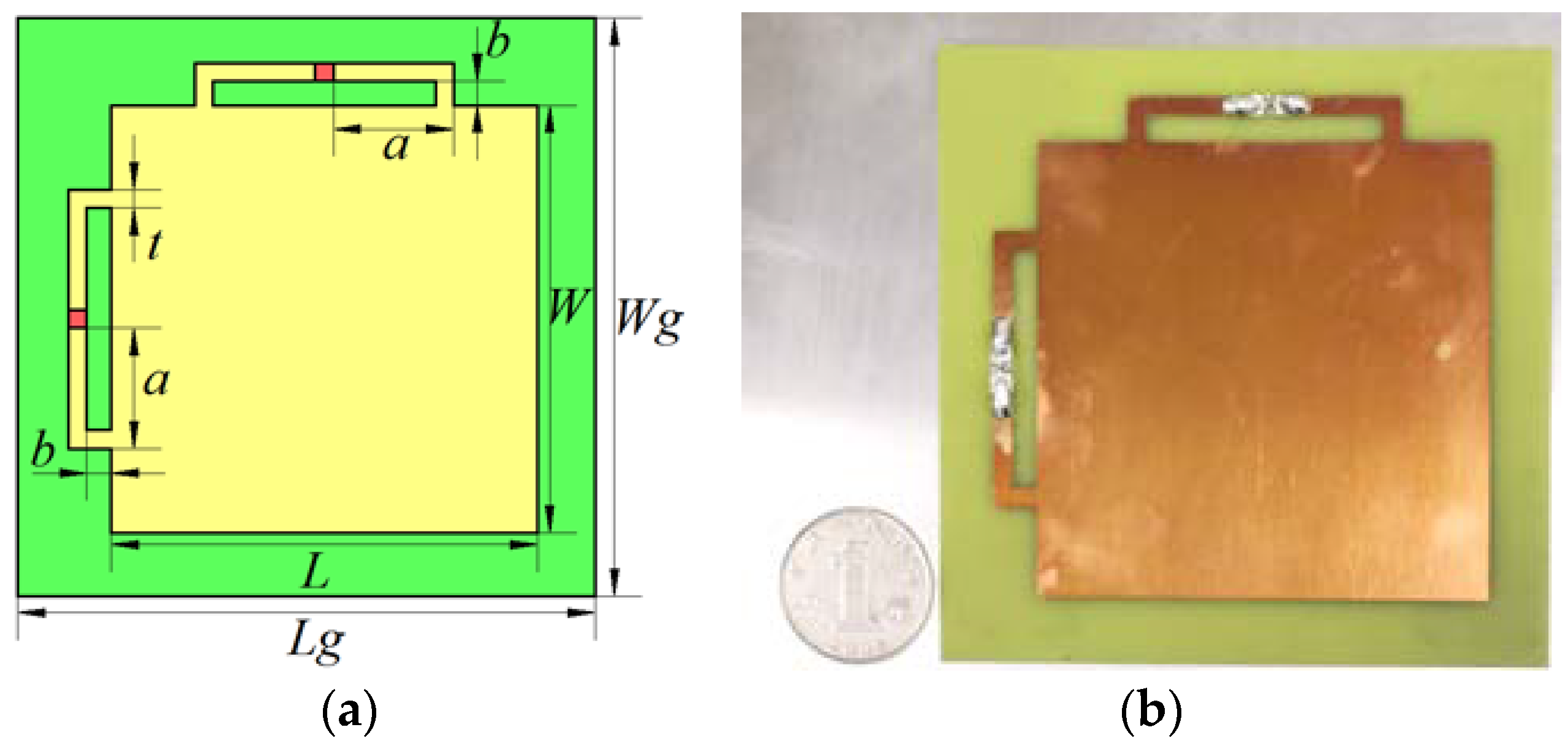
Figure 1. Path bypassing of the surface current of the (a) TM10 resonant mode and (b) TM01 resonant mode.
Proceedings 42 00003 g001
Figure 2. Structure of the RFID antenna sensor. (a) Theoretical diagram and (b) physical diagram.
Proceedings 42 00003 g002
Figure 3. Simulated crack propagation.
Proceedings 42 00003 g003
Figure 4. Wireless test system. (a) Schematic for wireless interrogation and (b) actual setup.
Proceedings 42 00003 g004
Figure 5. Characteristic curve. (a) Real part of antenna impedance, (b) imaginary part of antenna impedance, (c) S parameter and (d) resonant length variation and-crack length curve.
Proceedings 42 00003 g005
Figure 6. Relationship curve. (a) Reading distance and frequency” and (b) resonant length variation and crack length.
Proceedings 42 00003 g006
Table 1. Design parameters of the RFID antenna sensor.
ParameterMeaningValue
Lradiation patch length71 mm
Wradiation patch width71 mm
alength of microstrip long line20 mm
bwidth of microstrip short line3 mm
Lglength of ground plate and substrate96 mm
Wgwidth of ground plate and substrate96 mm
twidth of microstrip feed3 mm
Table 2. Crack test sensitivity.
Crack Length (mm)Resonant Length Shift (mm)Tested Sensitivity
40.140.07
80.560.15
121.220.23
162.610.31
203.770.39
Publisher’s Note: MDPI stays neutral with regard to jurisdictional claims in published maps and institutional affiliations.

