A New Experimental Test for the Characterisation of Masonry Shear Parameters †


Department of Structural, Geotechnical and building Engineering (DISEG), Polytechnic of Turin, 10129 Turin, Italy
*
Author to whom correspondence should be addressed.
†
Presented at 18th International Conference on Experimental Mechanics (ICEM2018), Brussels, Belgium, 1–5 July 2018.
Proceedings 2018, 2(8), 464; https://doi.org/10.3390/ICEM18-05369
Published: 18 June 2018
(This article belongs to the Proceedings of The 18th International Conference on Experimental Mechanics)
Abstract
:The shear properties evaluation on existing unreinforced masonry structure is usually performed through destructive tests. However, these tests have the characteristics of being very expensive and result in significant damage, not only to the samples but also on the portion of wall surrounding them. The present work illustrates the design of a new testing procedure for the characterisation of the shear properties in masonry panels for application in routine testing. In the aim of preserving the integrity of the area under testing, and to reduce the cost of the new testing procedure, it has been decided to use flat jacks. The numerical analyses used to design the test are presented, as well as the results of a first application of the procedure.
1. Introduction
Masonry is one of the most diffuse systems of construction. In many countries of the Mediterranean area (like Italy, Greece, Portugal, and Turkey) a considerable seismic activity and a high number of unreinforced masonry structures are present.
The behaviour of these types of constructions under seismic actions is markedly dependent on the shear properties of the material. On a masonry panel, the shear failure could happen by a diagonal crack or by the failure of the bed joint [1]. In this work, the diagonal crack failure is examined, and at the moment, has to be determined through destructive tests. These could be performed in laboratory [2] or in situ [3,4]. Tests performed in situ, like the diagonal compression test and the shear compression test, require the isolation of an important part of the wall to create the specimen. Laboratory tests have similar requirements, and add the risk of compromising the specimen upon transportation. The greatest problem of these tests is the high level and extent of damage that they require. This fact leads to their inapplicability in structures having historical/architectural relevance, and their high cost is prohibitive for application to ordinary buildings as well.
Shear strength and stiffness cannot be evaluated using non-destructive techniques. However, in the last two decades, some efforts have been made in order to create a moderate destructive test able to measure these characteristics [5,6,7,8]. The common feature of these studies is the utilisation of flat jacks. In fact, this technique can guarantee a limited destructiveness, and its flexibility allows experimentations. However, at the moment, these test methods are still not very common.
This study presents the first steps for the creation of a new experimental test for the characterisation of the masonry shear parameters using flat jacks. The set-up of this new test is implemented using two main parameters: obtain reliable results and contain the invasiveness of the test, in order to create a new moderate destructive technique. In this work are also presented the results of the first application of the test in situ.
2. Materials and Methods
As previously pointed out, the experimental test was designed with the intention of determining the shear characteristics of existing masonry panels using a moderate destructive technique based on flat jacks. After this design phase, it was possible to execute a first trial test on a masonry structure.
2.1. Test Set-Up Design
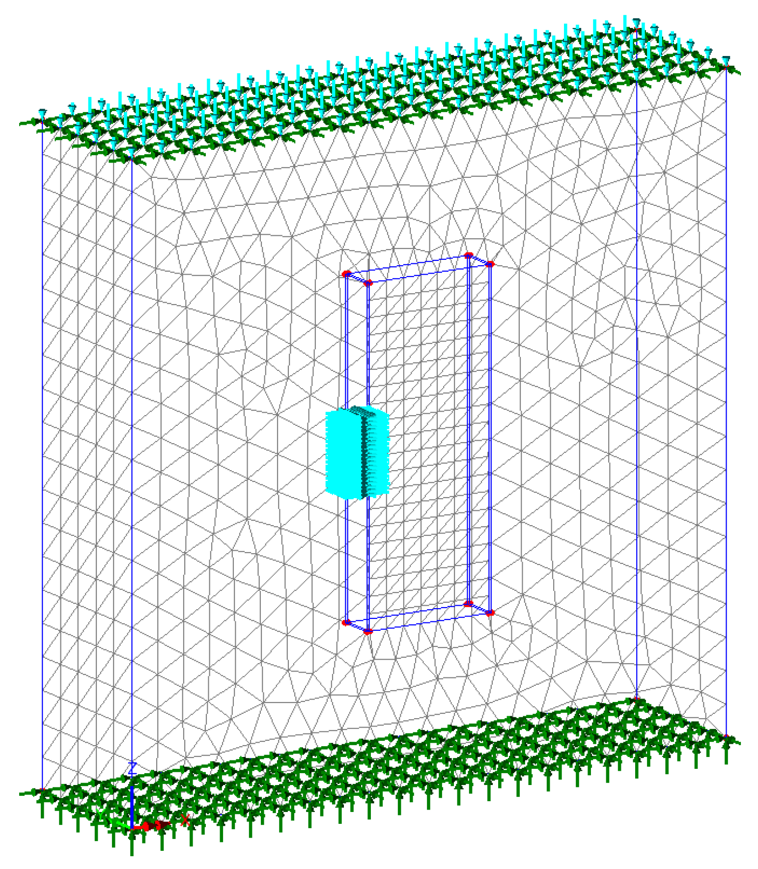
In this preliminary phase, the geometry of the test set-up was investigated. More specifically, linear elastic FEM (finite element method) analyses were performed on six different geometrical configurations. For these configurations, different positions, orientations, and numbers of both cuts and flat jacks were taken into account. The numerical models were performed considering the masonry as a homogenous isotropic material, and the configurations were supposed applied on a wall having dimensions of 2 × 2 × 0.5 m (Figure 1). In order to speed up this design phase, the numerical models were done considering rectangular-shaped flat jacks. For the sake of brevity, all of these configurations are not shown. The test set-up was chosen among these six layouts, accounting for destructiveness, costs, and orientation of the principal stresses.
As introduced, the main purpose of this work was the creation of a new moderately destructive test for the shear characterisation. For this reason, the destructiveness of the different layouts was deeply examined. For the definition of the optimal configuration, the destructiveness was taken into account considering the volume of the sample and the length, number, type, and orientation of cuts. For example, in configurations that use rectangular flat jacks, the cuts can be performed using a drill that usually does not need water to cool, and they can have limited depth (about 120 mm). On the contrary, cuts for semicircular flat jacks are usually performed using circular saws that normally are cooled using water that penetrates in the masonry, with the result being more invasive.
The limitation of the destructiveness was not the only factor considered for searching the best layout. The most important goal for the choice was the achievement of a 45° orientation of the principal stress, in order to have a diagonal direction of the stresses on the sample. Costs were also taken into account because they are one of the limitations for the application of destructive tests.
The found optimal configuration was a simple rotation of 45° of the standard double flat jack set-up (Figure 2). In fact, this configuration better fulfilled all the objectives. For this configuration, FEM analyses considering semicircular flat jacks were also performed. Due to the similarity with the double flat jack test, some recommendations given for the deformability test by RILEM [9] and ASTM [10] were adopted. One of these recommendations is the relative position between the two flat jacks.
2.2. First Trial Test
A first experimentation was performed in the “ex Teatro dei Nobili” (Vercelli, Italy) (Figure 3). This test was executed in collaboration with the Companies Cismondi Srl and ARCOS Engineering Srl. The building, made of brick and lime mortar masonry, has a long history that started in 1787. This structure was affected by a collapse, with associated injuries and victims. Successively, it was rebuilt, but a fire burned it down. Finally, at the beginning of the last century, the municipality repaired the structure, but it was abandoned after some years of utilisation.
The trial test was executed during a deep field investigation of the theatre, which involved also two couples of single and double flat jack tests. One of these couples of investigations was performed near to the experimental test, in order to obtain the vertical stress, the Young’s modulus, the Poisson’s ratio, and the compression strength.
All tests were performed using the same equipment. The used measurement system included a strain gauge having a base length of L = 250 mm (resolution of ±0.001 mm), seven measure bases (four parallel and three perpendicular to the flat jacks) and two pressure gauges: the first for pressures up to 1.60 MPa (±0.01 MPa) and the second for pressures up to 6.00 MPa (±0.05 MPa). The flat jacks were semicircular with dimensions 350 × 250 mm.
After the individuation of the test location, the positions of the flat jacks and of the seven measure bases were defined. The flat jacks’ positions were marked considering a relative distance of 500 mm, and the gauge points were glued at a distance equal to the base length. Subsequently to the glue hardening, it was possible to create the slots using a circular saw. The flat jacks were then inserted into the slots, and the hydraulic system was connected. Following the advice of the operator, instead of using oil, a solvent was used, in order to exploit its lower viscosity. Before raising the pressure, the upper plug of the upper flat jack was opened, and the solvent was pumped until the first liquid spilt, allowing the exit of all the internal circuit air.
Measures between the gauge points were taken before and after the first cut, after the second cut, and in correspondence to each step of pressure up to 2.60 MPa. It has to be remarked that for each step, the pressure was held until the measures were stable, and then the measures were recorded. This procedure was chosen to give time for the sample to end viscose deformations. Figure 3 highlights, in green, the perpendicular measure bases to the flat jacks, and in yellow, the parallel ones. The measurements allowed for the identification of the perpendicular strains ε┴ and parallel ε// to the flat jacks. These strains were evaluated averaging the measures; for example, ε┴ is computed as
where d┴,1 is the relative displacement of the first measure basis. The strain ε┴ is evaluated in the same way, but averaging on four measures. After this first operation, the shear strain was evaluated as
following (with another symbolism) the ASTM recommendation [2].
ε┴ = (d┴,1 + d┴,2 + d┴,3)/(3 L),
γ = ε┴ − ε//,
For the presented results, every relative displacement di,j was evaluated as the difference between the measure taken at a defined pressure step and the measure taken after the realisation of the two cuts.
The stress σ applied to the masonry is evaluated considering the well-known formulation used for the double flat jack test [9,10]:
where p is the hydraulic pressure, Km (< 1) is the dimensionless constant of the flat jack that takes into account its stiffness, and Ka (< 1) is the dimensionless constant evaluated with
in which AFJ is the flat jack area and AAV,SLOTS is the averaged area of the slots.
σ = p Ka Km,
Ka = AFJ/AAV,SLOTS,
3. Results
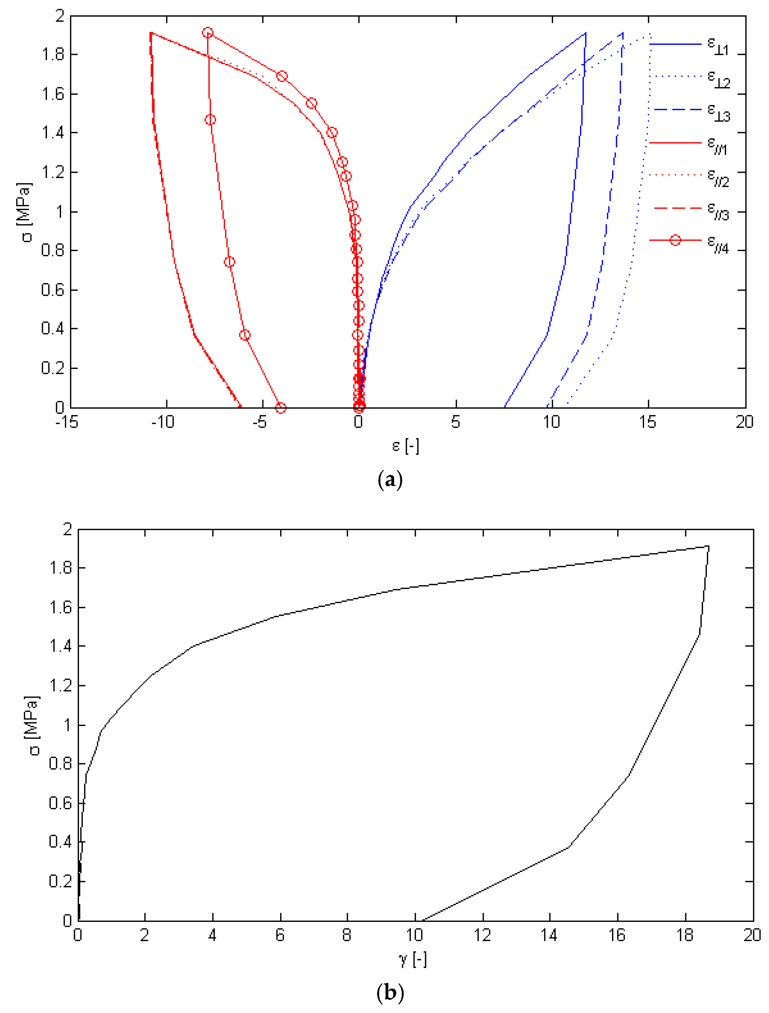
Results obtained from the new testing procedure are promising. The designed set-up has allowed to determine the behaviour of the masonry under the test, giving the relation between the applied stress and the measured strains (Figure 4a,b).
In the first part of the test, three cycles were performed, in which the pressure was kept at low levels (0.11, 0.15, and 0.29 MPa). This procedure was applied in order to have a better characterisation of the linear regime of the masonry. It is possible to identify, in both Figure 4a,b, an initial elastic behaviour. At a stress of approximately 0.80 MPa, the sample starts to show a plasticisation, and a hardening behaviour. This is a classical behaviour of the double flat jack test and is due to the confinement given by the masonry surrounding the specimen. The stress was then raised up to 1.91 MPa. At this point, it was impossible to have stable measures, and for this reason, it was decided to end the test and to take some measures during the unloading process.
The stress–shear strain curve (Figure 4b) was the greater achievement of this trial test. The plot shows clearly the initial elastic behaviour of the sample, and then it is quite easy to notice the plasticisation phase of the material. The individuation of these two phases is important for the evaluation of the shear strength and modulus of the masonry.
4. Conclusions
For this first test, some small criticalities were identified. The first is the difference among the three strains ε┴ and among the four ε//. Differences of this magnitude are quite normal for flat jack testing. In this case, the problem is connected to two principal facts. First of all, it was impossible to apply the measure bases perfectly perpendicular/parallel to the flat jacks. Secondly, the measure bases were only approximately near to the centre of the specimen. These two facts occurred because the masonry showed relatively thick joints, and in the equipment utilized the measure basis had a fixed length. These facts limited the possible positions of the gauge points (because it is not recommended to place the gauge points in joints) and led to this first criticality. A second issue was the creation of the slots that resulted in them being not perfectly parallel. This fact was related to the non-smooth operation of the saw when cutting in a direction not aligned with bed joints.
However, the results are very promising. In fact, the first trial test has highlighted the potential of the configuration chosen for the shear characterisation. The obtained data point out that, using this test, it is possible to recognise the linear and the non-linear behaviour of the material. The identification of the linear regime of the masonry and the measurement of the shear strain can identify the shear modulus of the material. Similarly, the detection of the zone in which the transition between the linear and the non-linear behaviour is present should be related to the shear strength of the masonry. These facts underline, clearly, the possibility to use this set-up as a new moderately destructive test for the shear characterisation.
Authors have already planned further activities having the purpose of validating this new shear test. These activities are:
- A special frame was designed and built to guide the creation of the slots and the placement of measuring instruments. Moreover, a special data acquisition system to log real-time data has been developed, and monitoring of the specimen using acoustic emission technique and digital image correlation is planned.
- Further numerical analyses are being executed in order to have a better comprehension of the sample behaviour and correlate in situ results with shear strength and modulus.
Author Contributions
Both the authors have contributed to all the phases of this work.
Funding
This research received no external funding.
Acknowledgments
The authors thank Cismondi Srl for the cooperation, material, equipment and work done for the execution of the trial test and ARCOS Engineering Srl that allowed the experimentation during its own work on the structure.
Conflicts of Interest
The authors declare no conflict of interest.
References
- Atkinson, R.H.; Amadei, B.P.; Saeb, S.; Sture, S. Response of masonry bed joins in direct shear. J. Struct. Eng. 1989, 115, 2276–2296. [Google Scholar] [CrossRef]
- ASTM International. E519/E519M-15 Standard Test Method for Diagonal Tension (Shear) in Masonry Assemblages; ASTM International: West Conshohocken, PA, USA, 2015. [Google Scholar]
- Turnsek, V.; Sheppard, P.F. The shear and flexural resistance of masonry walls. In Proceedings of the Research conference on Earthquake Engineering, Skopje, Macedonia, 8–13 September 1980; pp. 517–573. [Google Scholar]
- Brignola, A.; Frumento, S.; Lagomarsino, S.; Podesta, S. Identification of shear parameters of masonry panels through the in-situ diagonal compression test. Int. J. Arch. Herit. 2008, 3, 52–73. [Google Scholar] [CrossRef]
- Foppoli, D.; Pulcini, A. A New Method to Test Masonry Shear Characteristics Thought Flat Jack (FJ-SCT Method). In Proceedings of the 19th World Conference on Non Destructive Testing, Munich, Germany, 13–17 June 2016. [Google Scholar]
- Caliò, I. La prova di scorrimento con martinetto piatto. In Proceedings of the XIV ANIDIS (Italian Nacional Association of Earthquake Engineering); Italian Nacional Association of Earthquake Engineering: Matera, Italy, 2011; p. 157. [Google Scholar]
- Jurina, L. La caratterizzazione meccanica delle murature parte seconda: Martinetti piatti. In Proceedings of the International Conference CIAS, Nicosia, Cipro; 2007; pp. 133–150. Available online: https://re.public.polimi.it/handle/11311/247406?mode=full.23 (accessed on 26 July 2018).
- Gambirasio, L.; Roberti, G.M.; Rizzi, E. Numerical simulations of flat-jack test set-ups for the local shear characterisation of masonry panels. Int. J. Mason. Res. Innov. 2016, 1, 306–329. [Google Scholar] [CrossRef]
- RILEM TC 177-MDT. Masonry durability and on site testing D.5. In situ stress-strain behavior test based on the flat-jack. Mater. Struct. 2004, 37, 497–501. [Google Scholar]
- ASTM International. C1197-14a Standard Test Method for In Situ Measurement of Masonry Deformability Properties Using the Flat jack Method; ASTM International: West Conshohocken, PA, USA, 2014. [Google Scholar]
Figure 1.
The finite element method (FEM) model for one of the six examined configurations. In the figure, the cyan horizontal arrows show the position of the flat jack, and the nearby blue lines are the cuts. The green arrows represent restrains, while the top cyan vertical arrows show the vertical load.

Figure 2.
A FEM result obtained for the chosen configuration. The model was created considering a homogeneous elastic material having E = 1200 MPa, υ = 0.25. In order to simulate the vertical load coming from the upper part of the structure, a vertical stress of 0.2 MPa was considered. The figure shows the result obtained considering a stress of 0.5 MPa applied by the flat jacks.
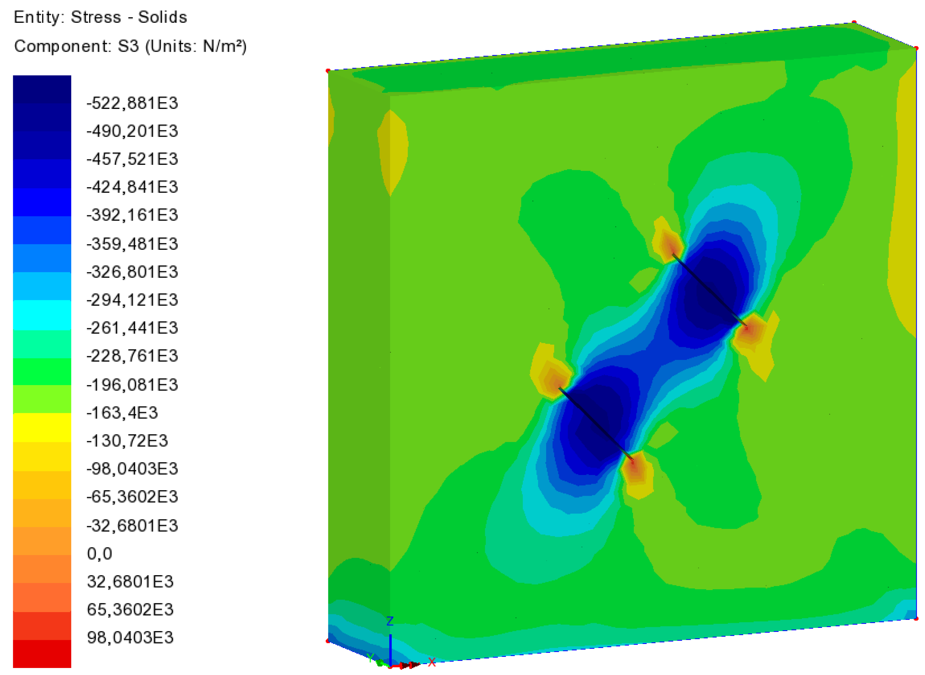
Figure 3.
Equipment set-up of the first trial test performed on the “ex Teatro dei Nobili” (Vercelli, Italy). In this image, it is possible to recognise the slots with the inserted flat jacks and the hydraulic connection between them. The positions of the gauge points and the direction of the seven measure bases are highlighted (three perpendicular in green and four parallel in yellow).
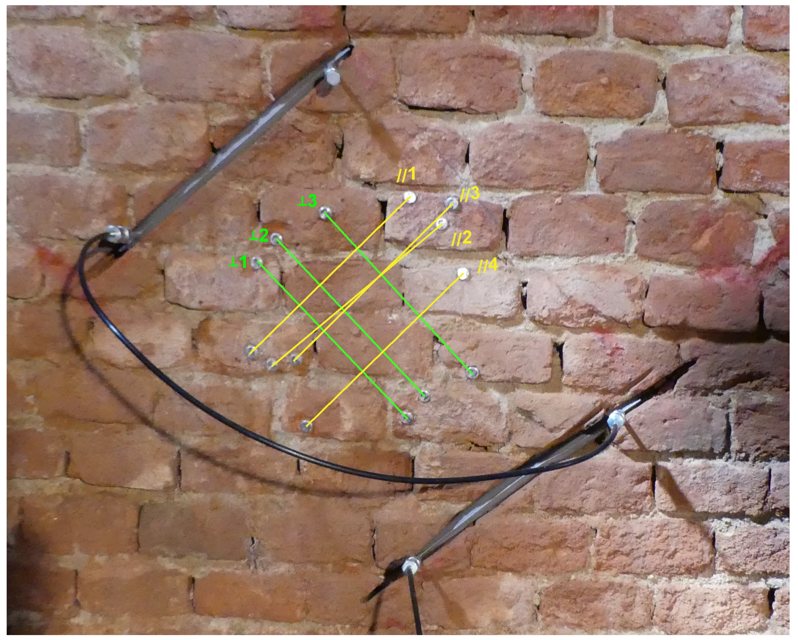
Figure 4.
Results obtained in the trial test: (a) plots of the stress applied to the masonry σ versus the deformation of the three perpendicular bases ε┴ (in blue) and (in red) the four parallel bases ε// (elongations are considered negative); (b) plot of the stress applied to the masonry σ versus the shear strain γ.

Publisher’s Note: MDPI stays neutral with regard to jurisdictional claims in published maps and institutional affiliations. |
© 2018 by the authors. Licensee MDPI, Basel, Switzerland. This article is an open access article distributed under the terms and conditions of the Creative Commons Attribution (CC BY) license (https://creativecommons.org/licenses/by/4.0/).
Share and Cite
MDPI and ACS Style
Viale, N.; Ventura, G. A New Experimental Test for the Characterisation of Masonry Shear Parameters. Proceedings 2018, 2, 464. https://doi.org/10.3390/ICEM18-05369
AMA Style
Viale N, Ventura G. A New Experimental Test for the Characterisation of Masonry Shear Parameters. Proceedings. 2018; 2(8):464. https://doi.org/10.3390/ICEM18-05369
Chicago/Turabian StyleViale, Nicola, and Giulio Ventura. 2018. "A New Experimental Test for the Characterisation of Masonry Shear Parameters" Proceedings 2, no. 8: 464. https://doi.org/10.3390/ICEM18-05369