1. Introduction
As a typical membrane structure, inflated balloons have considerable importance in a number of scientific studies and technological applications. On the macro scale, they can be used in terrestrial and space structures due to their advantages, being light-weight, quick and self-deployed, and having compact storage properties [
1] (Jenkins, 2001). On the micro scale, they can be used as animal or plant cells [
2] (Moretti et al., 2004).
Investigations into the contact behavior of inflated membranes can be summarized as two processes: geometry nonlinearity analysis and boundary condition nonlinearity analysis. Geometry nonlinearity is carefully considered when solving the membrane inflation problem [
3] (Feng and Yang, 1970). Moreover, a lot of work has been done to deal with the nonlinearity problem of the boundary condition [
4] (Feng and Yang, 1973, Johnson, Kendall and Roberts, 1971). Broadly, the solution schemes proposed to this problem are divided into two categories: finite element analysis and a semi-analytical approach. Based on the finite element method, the membrane’s large deformation problems, nonlinear static behavior, inflation and contact characteristics were analyzed by Leonard and Verma (1976) [
5] and Charrier and Shrivastava (1987) [
6]. On the basis of different contact models (Yang and Feng, 1973; Patil and DasGupta, 2015) [
7], the contact problems were simplified to a set of ordinary differential equations, which can be solved by numerical methods.
In the existing literature, diverse methods are proposed based on variational formulation. The coupled normal adhesive force and tangential friction force will increase the difficulty of the solving process. To deal with this problem, a semi-analytical method rooted in differential formulation is introduced to extend the modal of Feng and Yang (1973) [
8], and more complex contact boundary conditions are studied.
2. Geometry and Constitutive Models
A spherical balloon with the uninflated radius
and uniform thickness
(state I the black line) is inflated to radius
by pressure
(state II the red line). Then two parallel rigid plates are pressed by
into contact with the balloon (state III the green line). Half of the spherical balloon and one rigid plate are shown in
Figure 1. The inflated spherical balloon before contact is described by the spherical coordinates (
,
,
). The cylindrical coordinates (
,
,
) are used for the spherical balloon after contact.
The governing differential equations are built for the non-contact region and the contact region, separately.
In the non-contact region: according to the geometric relation, the principal stretch ratios for the membrane can be written as
. Here, the subscripts
and
denote the meridian and circumferential directions.
The prime in the foregoing and subsequent equations denotes the derivatives with respect to the angle .
The structure is considered as the non-moment thin shell, which has no bending moment and torsion on the cross-section, and the equilibrium differential equations can be expressed due to the constitutive relation and the axial symmetry.
where
=
and
=
are the external loads acting on the deformed surface in the normal and meridian tangential directions.
Based on the Mooney–Rivlin hyperplastic constitutive model, the equilibrium equations can also be obtained due to the newly-defined variables:
(Feng and Yang (1973)):
In the contact region: the complex stick–slip contact condition becomes a frictionless contact condition when the friction coefficient becomes zero. If the friction coefficient goes to infinity, it is converted into the no-slip contact condition. This contact condition is considered in this paper. As the friction coefficient is limited, the material will stick when the interfacial friction is greater than the membrane tension, while the others will slip.
The equilibrium equation along the meridian tangential direction of the spherical balloon in the contact region can be rewritten as . Hence, the equilibrium condition for the critical sliding state can be obtained.
3. Results and Discussion
3.1. Experiment Verification
In order to verify the theoretical results, a testing scheme was proposed to measure the patterns and some important contact characteristics of the inflated balloon. The detailed material and structural parameters are shown in
Table 1.
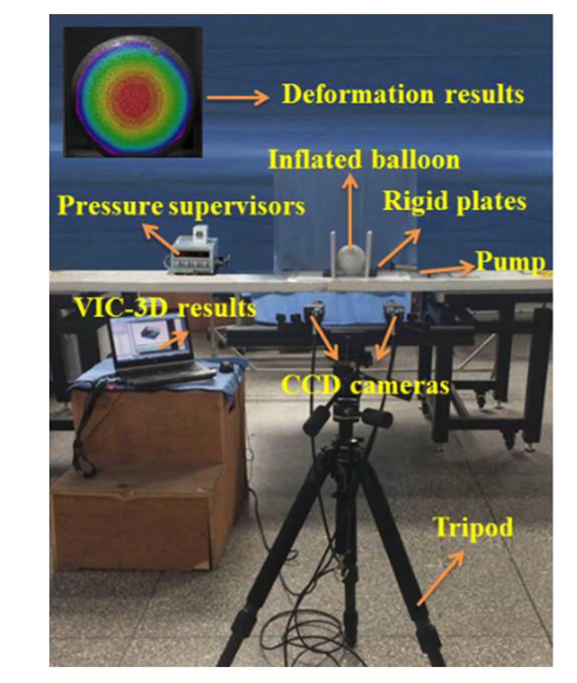
Before the experiment, the speckle pattern on the balloon was reproduced artificially. To increase the contrast of the speckle, matte white paint and black paint were sprayed evenly on the balloon surface. In the experiment, the balloon with the sprayed speckles was placed on the workbench and its position was adjusted so that it was on the compression axis. After that, the balloon was inflated by the pump. The displacement load was applied to the balloon, which can be controlled precisely by the electronic universal testing machine. This load was noted by a ruler on the machine and the internal pressure of the balloon was monitored by the barometer (
Figure 2). The deformation of the balloon were tested using the digital image correlation (DIC) technology, which is a reliable means for measuring displacement fields.
The maximum displacement of the balloon (
) is compared in
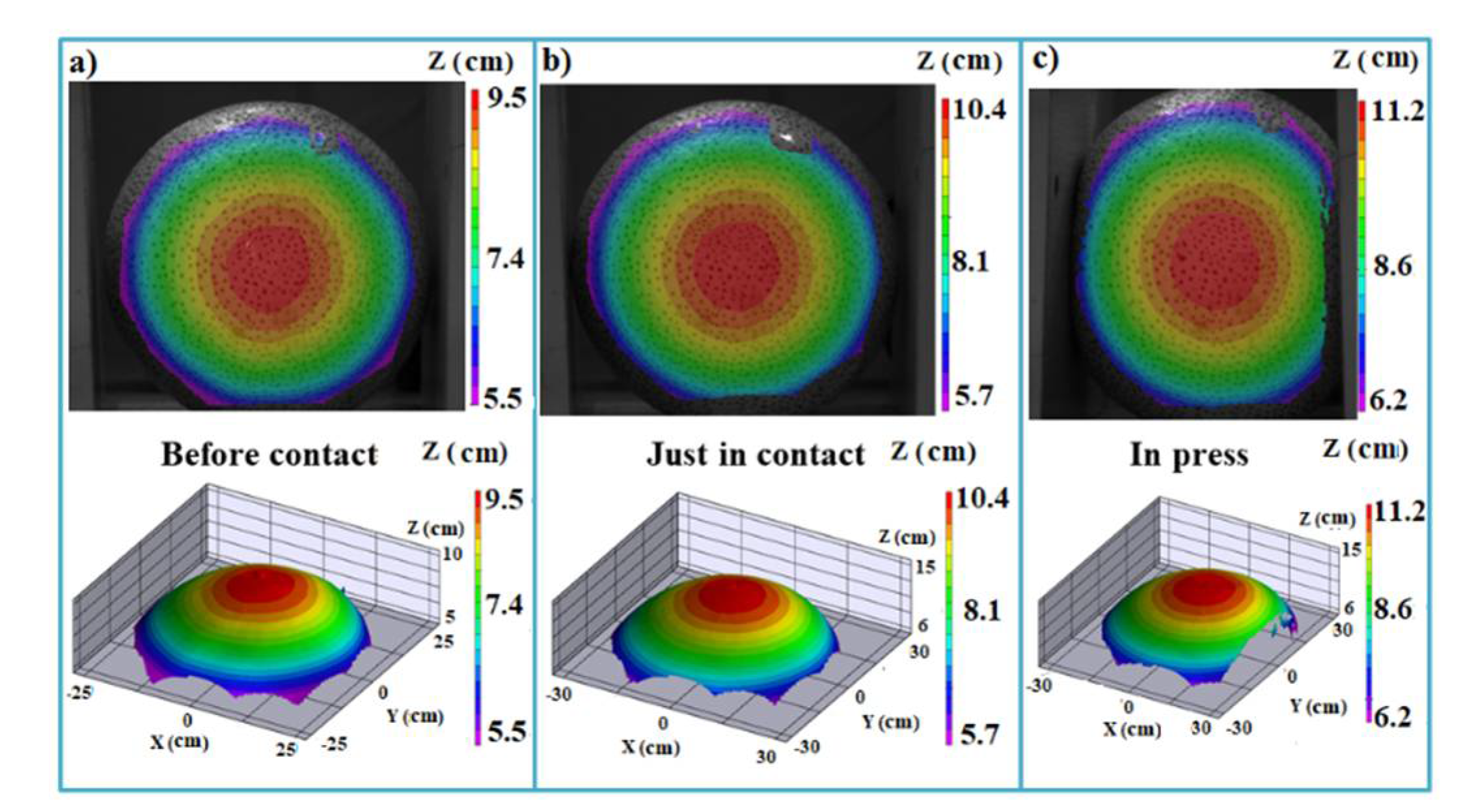
Table 2 and the deformation contours of the balloon are presented in
Figure 3.
When the inflated balloon is just in contact with the plates, the maximum displacement appears in the middle (). The tested deformation (10.4 cm) agrees with the theoretical result (10.0 cm), with an error around 0.33%. When the displacement load is 4.25 cm, the error reaches the maximum, which is 6.8%.
3.2. Theoretical Prediction
As a general case, the results from the stick–slip contact condition are discussed in this section.
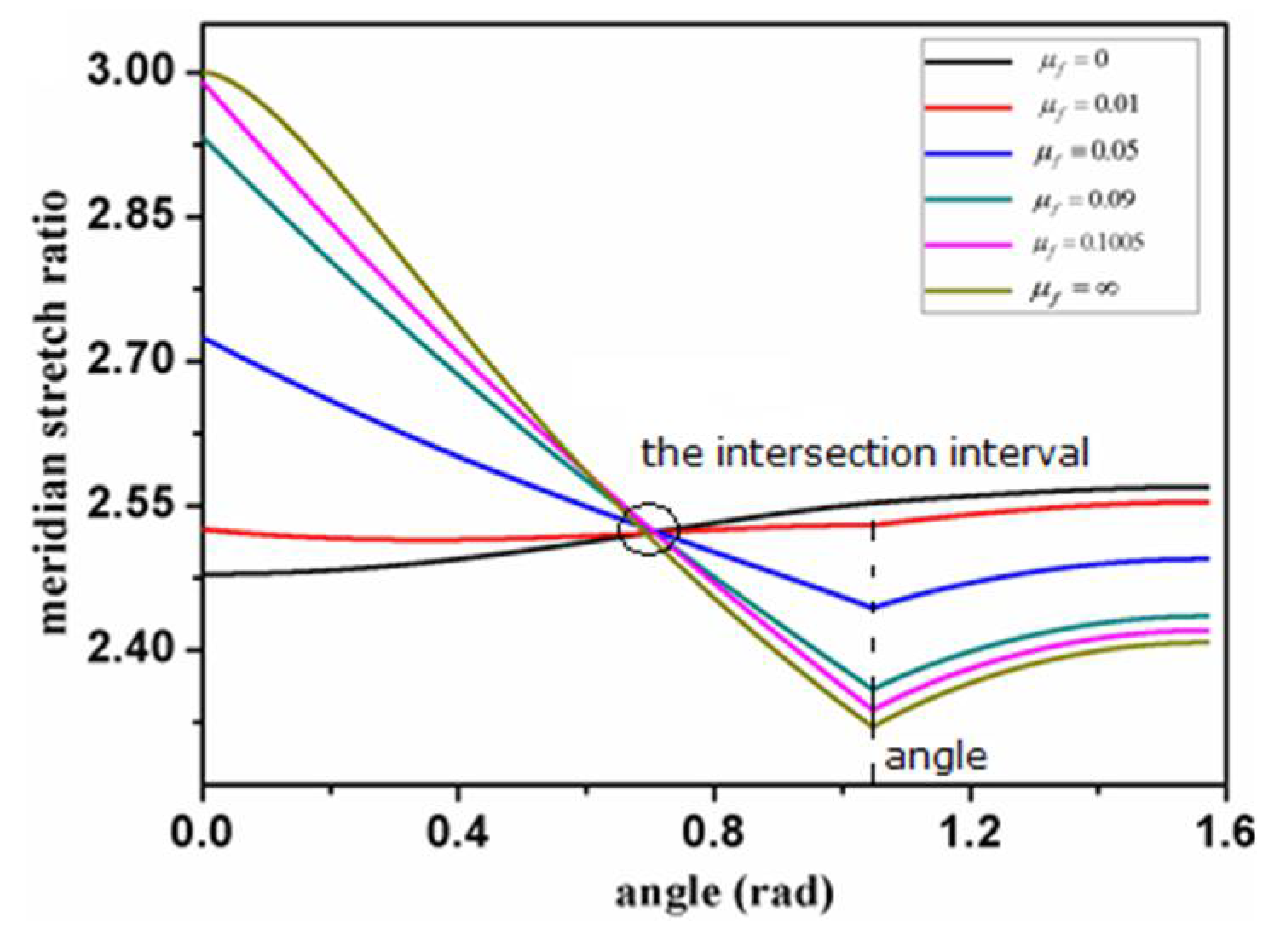
For different friction coefficients, the changing trend of the meridian stretch ratio
with the angle
is shown in
Figure 4, where the contact angle is
.
Two special phenomena can be seen in
Figure 4. One is that the intersection points of all curves fall in a small interval, and the other is the dividing point (
). The intersection point of any two curves appears in the contact region, which represents that materials have the same meridian stretch ratio under conditions with corresponding friction coefficients at that point. Moreover, in contrast to the condition of
, a dividing point, which is the boundary of the contact and non-contact regions, appears when friction is introduced.
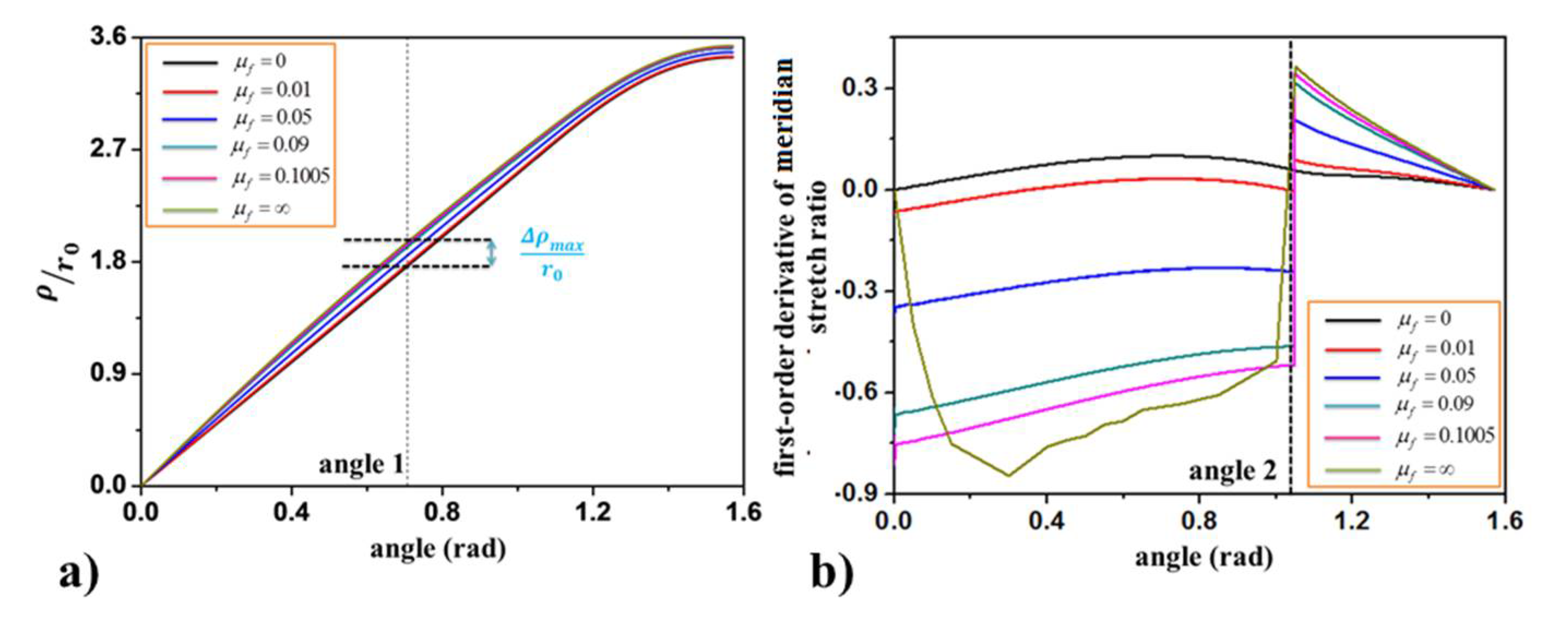
To better explain the intersection interval in
Figure 4, the relationship between the horizontal ordinate and angle is counted in
Figure 5a, and the horizontal ordinate difference between the introduced friction conditions and the frictionless conditions are described in
Figure 5b. In the contact region, the relationship
is satisfied. Then the intersection of any two curves represents the same changing rate of the horizontal ordinate
, resulting in the maximum difference at that point.
Moreover, a step point appears at
in
Figure 4, which corresponds to the dividing point between the contact and non-contact regions in
Figure 5b. This means the changing trend of the meridian stretch ratio is different in the contact and non-contact regions, though this stretch ratio changes continuously in these two regions.
4. Conclusions
In this paper, a semi-analytical approach based on the force equivalent method is introduced to the Mooney–Rivlin hyperelastic membrane model to characterize the rigid–flexible contact behavior of an inflated membrane balloon. In the contact region, the typical stick–slip condition is considered. The inflatable and contact process can be tracked using the proposed model. The patterns and characteristics before contact, just in contact and in press can be verified by experimental tests.
Considering the particularity of the stick–slip contact condition, friction plays an important role. A small intersection interval appears in the meridian stretch ratio for different friction coefficients in the contact region, and the horizontal ordinate changing ratio of any two conditions with different friction coefficients remains the same, resulting in the maximum difference of this ordinate. Unlike the increasing meridian stretch ratio with the increment of the angle when the friction coefficient is zero, a dividing point appears between the non-contact and contact regions when friction is introduced. It declines in the contact region and increases in the non-contact region due to the interface friction, which prevents the material of the balloon from sliding to the pole.


