Proceeding Paper

Experimental Study on Spallation of Titanium Alloy Plates under Intense Impulse Loading †

1
National Key Laboratory of Transient Physics, Nanjing University of Science and Technology, Nanjing 210094, China
2
China Ship Development and Design Center, Wuhan 430064, China
3
Institute of Fluid Physics, China Academy of Engineering Physics, Mianyang 621900, China
*
Author to whom correspondence should be addressed.
Presented at the 18th International Conference on Experimental Mechanics, Brussels, Belgium, 1–5 July 2018.
Proceedings 2018, 2(8), 403; https://doi.org/10.3390/ICEM18-05240
Published: 20 May 2018
(This article belongs to the Proceedings of The 18th International Conference on Experimental Mechanics)

Abstract

:
The dynamic response and spall characteristics of a double-layer TC4 titanium alloy thin target under intense impulse loading was investigated experimentally using electric gun technique. A velocity-measuring instrument, known as VISAR (velocity interferometer system for any reflector), measured the free surface velocity of targets. Typical characteristic parameters of the velocity were calculated by the obtained data. The deformation/failure modes of the samples were analyzed, and based on stress wave propagation theory, the spall thickness was derived. Furthermore, it was found that the oscillation period of the free surface velocity can be used to estimate the location of spalling damage, but cannot directly reflect the full spallation of the target.

1. Introduction

The spallation of ductile metals under strong impact loading is of considerable interest for basic studies and engineering applications, such as weapons, armored protection, and aviation spacecraft. After extensive theoretical and experimental studies, many theoretical damage models have been developed to describe and predict phenomena of spall fracture. Up to now, based on damage evolution, spallation is a physical and mechanical process resulting from nucleation, growth, and coalescence of multiple voids, and finally leading to catastrophic fracture of materials [1,2,3].
Titanium alloy, as an important structural material, provides light density, high specific intensity, and excellent resistance to corrosion. Because of these advantages, titanium alloy is widely used in weight-sensitive applications, such as aerospace, transportation, and military. Many scholars conducted detailed studies on their dynamic responses subjected to impact loading. Rosenberg et al. [4] measured the Hugoniot curve of TC4 within 0–14 GPa. The Hugoniot curve in the stress-particle velocity curve showed a break around 10 GPa which could be attributed to a dynamic phase transformation. Millett et al. [5] investigated the role of anisotropy in the response of the TC4 titanium alloy under shock loading. It was found that there is little or no difference in the equation of state of this alloy when loaded either parallel to or radial to the long axis of the original bar stock. Me-bar et al. [6] conducted a series of experiments to study the spall strengths and fracture mechanisms of TC4 with different microstructures. It was shown that the change in microstructures hardly affected the spall strength of TC4, although it was closely related to the spalling mechanism. No relation could be found between spall strength and spalling mechanism. Dandekar and Speltzer [7] found that the spall strength of TC4 increased with the pulse duration, ranging from 3.3 to 4.2 GPa. Wielewski et al. [8] investigated the micromechanics of spall initiation and propagation in TC4 during shock loading. It was found that spall initiation occurred by the nucleation of voids at the grain boundaries between plastically hard/soft grains of the dominant hcp α phase. Ren et al. [9] systemically investigated the mechanical response and spall fracture behavior of an extra-low interstitial grade TC4 during one-dimensional shock loading. As adiabatic shear bands are easily formed in titanium alloys under impact loading, researches on them mainly focus on single-layer thick or medium thick targets. However, there is little study on dynamic responses of targets with two or more layers under intense impulse loading.
In this paper, an electric gun has been used to experimentally study the dynamic response of double-layer TC4 titanium alloy thin targets. A velocity-measuring instrument, known as VISAR (velocity interferometer system for any reflector), was applied to measure the free surface velocity of targets. According to the obtained curve, the spall location, the impact pressure, and the strain rate under the corresponding conditions were calculated. On the basis of experiment and further through metallographic analysis, it was found that the oscillation period of the free surface velocity was not a sign of the spallation of targets.

2. Experimental Method

2.1. Experimental Principle

The square specimens adopted in the tests were double-layer TC4 titanium alloy thin plates. The first layer was thicker than the second layer, with thicknesses of 2 mm and 1 mm, respectively. Plate impact experiments were conducted to generate intense impulse loading. When a flyer impacts the double-layer target, a shock wave is introduced to each of the flyer and the target. The shock wave in the target passes through the interface to the second layer and reflects as a rarefaction wave at the back surface, because the direction of motion of the material caused by rarefaction wave is opposite to that of the shock wave. When two oppositely moving rarefaction waves reflected from the free surfaces of the flyer and the target meet in the second layer target, a tensile stress is generated. If the stress is large enough and remains for some time, the material will be damaged or destroyed. Afterwards, the rarefaction wave reflected from the free surface of the target propagates to the interface, the interface is pulled apart due to its inability to withstand tensile stress, and the impact pulse is confined within the second layer target.

2.2. Experimental Set-Up

In this experiment, an electric gun with the energy of 14.4 kJ that was operational at Institute of Fluid Physics, CAEP, was employed as a loading device [10]. VISAR was applied to measure the free surface velocity of targets, and the data of the gauge was recorded by an oscilloscope. The principle of the electric gun is based on metal foil explosion by pulsed large current. As illustrated in Figure 1, the electric gun was connected to a series RLC circuit. After the triggering switch turned on, the energy stored in the capacitor was released and a pulsed large current generated. The foil was designed to be the minimum cross-sectional area of the bridge-foil load and the most resistive element in the circuit. Hence, when the transmission line delivered the current from the capacitor bank into a foil, the foil absorbed most of the ohmic heating. If the discharge time of the bank was short compared to thermal diffusion time away from the foil, the metal foil explosion occurred.

3. Results and Discussions

3.1. Character of Free Surface Velocity

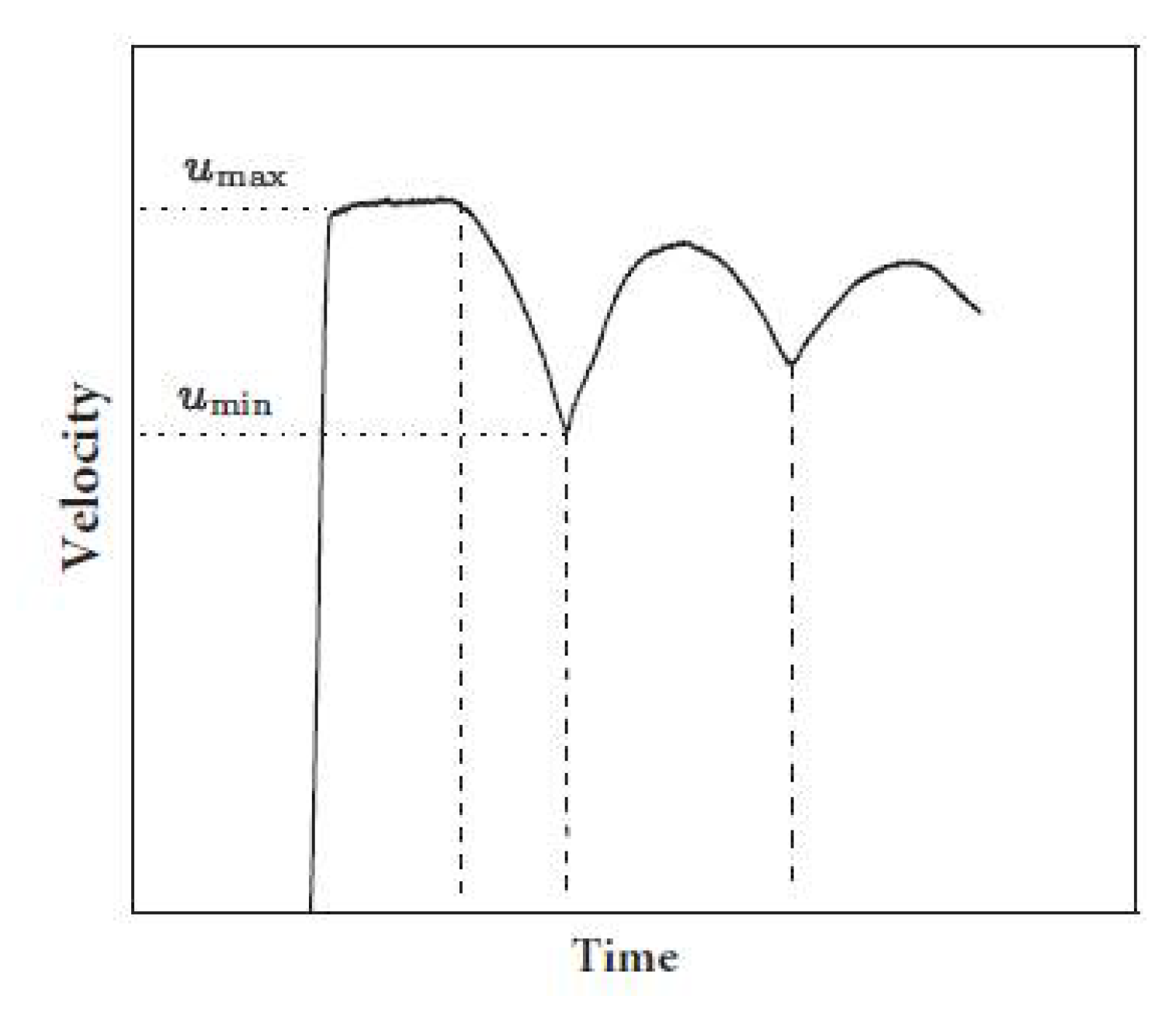
Figure 2 shows the typical free surface velocity profile of ductile metals under impact loading. According to interaction of waves and acoustic approximation, spallation strength, tensile strain rate, and impact pressure can be obtained from the curve. Neglecting the influence of elastoplastic deformation, the value of spallation strength can be calculated by the following equation:
σ s = 1 2 ρ 0 c b Δ u 1 ,
where ρ 0 and c b are the initial density and bulk acoustic velocity, respectively, and Δ u 1 = u max u min is the free surface velocity difference in the unloaded zone.
In the curve, it is difficult to find the beginning of the stretching process. Therefore, the average strain rate is regarded as the tensile failure strain rate. Its value can be calculated using
ε ˙ = 1 2 c b Δ u 1 Δ t 1 ,
where Δ t 1 is the stretching duration, i.e., the time difference between the first peak and the first minimum.
The oscillation period of the velocity is often used to determine whether the material is completely spalled. The thickness of the spall scab derived from the period is given by
h s = 1 2 c l Δ t 2 ,
where Δ t 2 is the first oscillation period and c l is the elastic longitudinal wave velocity.
From the conservation of wave action, the impact pressure can be calculated by
P = ρ 0 D u p = ρ 0 ( c b + λ u p ) ,
where D is the shock wave velocity and λ is the Grüneisen parameter. The particle velocity u p is approximately equal to half the velocity of the free surface, i.e., u p = 1 2 u .

3.2. Experimental Results

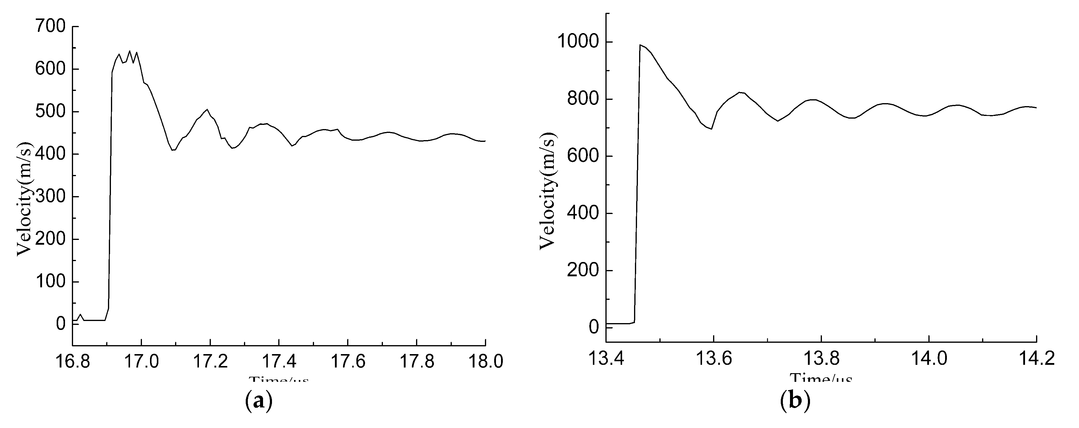
The experimental results were divided into two categories: quantified results and observed results. The quantitative results obtained in this experiment included impact velocity, free surface velocity, impact pressure, spallation strength, and tensile strain rate. Figure 3 shows the free surface velocity profile of the samples at velocities of 1.78 km/s (Sample 1) and 2.33 km/s (Sample 2). Table 1 summarizes the quantification results obtained from the experiment.
Figure 4 shows the deformation/failure modes of the samples at different impact velocities. It can clearly be observed from the figure that the first layers of the two samples have an inelastic deformation, and the second layers, with no spall scab formed on their rear side, have the shape of a square disk.

3.3. Analysis and Discussion

Compared with TC4 thick target of the literature [9], it can be found that from Figure 4 the deformation/failure modes of thin targets are obviously different from those of thick targets. For a single-layer thick target, if the intensity of impulse loading formed by the flyer was large enough and remained for some time, the spall scab was pulled out. For a double-layer thin target, after impacted by a flyer, most of the shock waves induced in the first layer propagated through the interface to the second layer. Then the waves were reflected at the surface of the second layer. The reflected waves collided with the sparse waves reflected by the free surface of the flyer, causing the target’s tensile spallation. On the other hand, the two targets separated when the reflected waves reached their interface. After their separation, the stress waves in the first layer were not large enough to cause spallation, so only inelastic deformation occurred in it. Furthermore, the shock waves confined within the second layer retained most of the energy of the impulse loading. But because the planar stress waves were concentrated mainly within the middle zone, its plastic deformation was also localized in this zone, as shown in Figure 4a. As the velocity (energy) of the flyer increased, the second layer demonstrated a combination failure mode of shear and spallation, as shown in Figure 4b: irregular circle shear cracks on the front side, and spalling cracks on the back side.
By observing the appearance of the recovered samples, it was not possible to determine whether the second layer target was spalled or not. However, the location of spallation can be obtained through the analysis of the velocity curve. On this basis, the location of the spall plane was rederived by theoretical analysis, and a metallographic experiment was performed to confirm if the sample was spalled. Although the velocity of the one-dimensional strain wave was higher than that of the plastic wave, the amplitude of the latter was small. According to the acoustic approximation, and neglecting the effects of the elastic wave, the location of the spall plane was given by:
d f D f + d f D f + h h s D t = h D t + h s D t ,
h s = D t D f d f ,
D f = d f h s D t ,
where D t and D f were the shock wave velocities of the target and the flyer, respectively, and h was the total thickness of the target. If the shock Hugoniot curve of the target and flyer is known, the thickness of the spall scab can be estimated by Equation (6). The wave velocity under high pressure was the basis for the study of high-pressure material models. Unfortunately, it was impossible to measure or calculate the shock wave velocity of Mylar flyers in this experiment. However, through Equation (7), the shock wave velocities of Mylar flyers for Specimens 1 and 2 were calculated to be 5348 m/s and 7268 m/s, respectively, which were far higher than that of its volume velocity of about 2200 m/s.
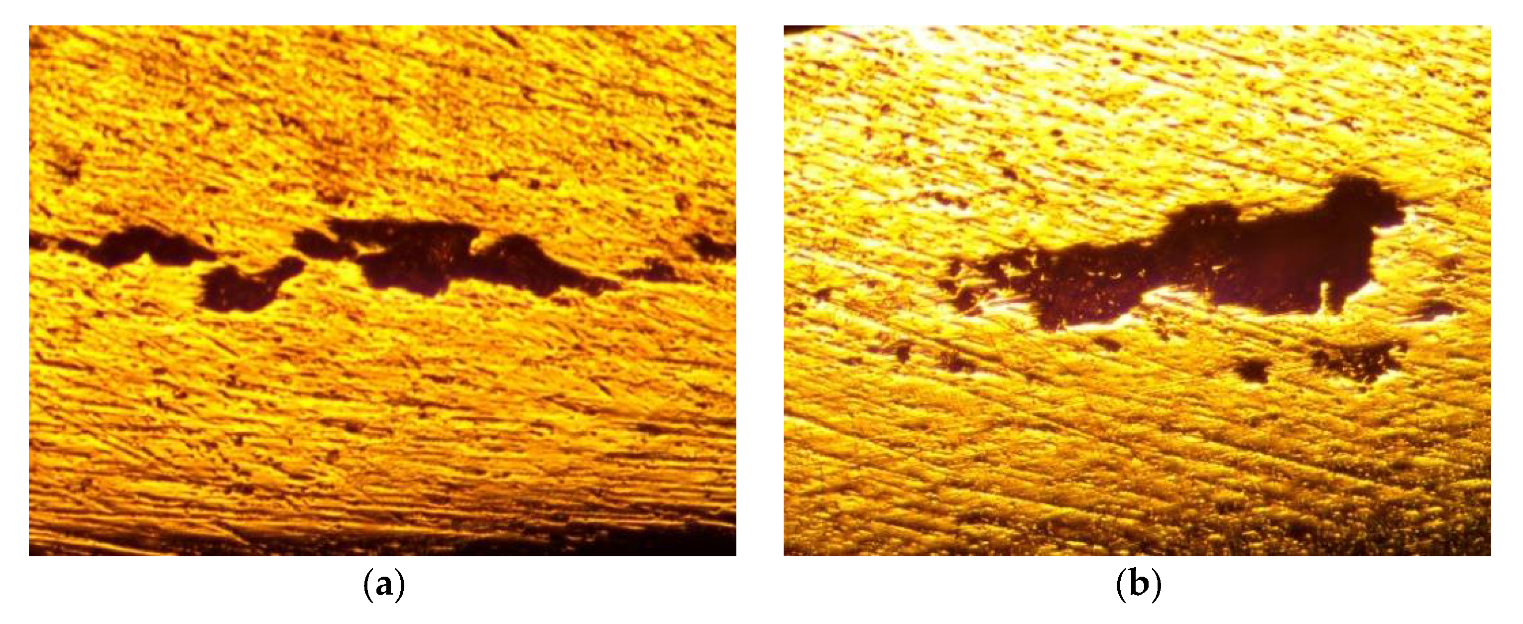
Table 1 presents the location of the spall plane obtained from the velocity oscillation period. In order to observe the damage inside the target, the recovered second layers were cut and polished to perform metallographic analysis. It can be clearly seen from Figure 5 that spall had initiated and began to propagate. Spallation is a physical and mechanical process resulting from nucleation, growth, and coalescence of multiple voids. It is obvious that the plates in Figure 5 were in the stage of growth and coalescence of multiple voids. At this stage, no complete spall planes had been formed. However, the aggregated voids could not be bypassed; the stress waves only propagated between the damaged surface and the free surface. It is also consistent with the results of the velocity profile analysis. These results clearly demonstrate that the location of the spall plane can be obtained from the velocity curve, but it is impossible to determine whether the target is completely spalled or not from it.

4. Conclusions

In this paper, an electric gun has been used to experimentally study the dynamic response of double-layer TC4 titanium alloy thin targets. In the tests, velocity history at the midpoint of the back was measured by VISAR. Based on experimental observations, the deformation/failure modes of thin targets and thick targets were compared. The spallation strength, tensile strain rate, and impact pressure of the samples were calculated using the velocity profiles recorded by VISAR. On this basis, the location of the spall plane was rederived by theoretical analysis, and the shock wave velocity of the Mylar flyer at the corresponding test conditions was obtained. In addition, it was found by metallographic analysis that the location of the spall plane can be acquired from the free surface velocity, but the damaged surface may be in the stage of growth and coalescence of multiple voids.

Author Contributions

Y.Z. and Y.S. conceived and designed the experiments; Y.Z., J.M. and F.T. performed the experiments; Y.Z., Y.S. and R.L. analyzed the data; Y.Z. wrote the paper.

Acknowledgments

This work was supported by the Postgraduate Research & Practice Innovation Program of Jiangsu Province under Grant KYCX17_0393 and the Fundamental Research Funds for the Central Universities through Grant No. 30916011348.

Conflicts of Interest

We declare that we do not have any commercial or associative interest that represents a conflict of interest in connection with the work submitted.

References

  1. Curran, D.R.; Seaman, L.; Shockey, D.A. Dynamic failure of solids. Phys. Rep. 1987, 147, 253–388. [Google Scholar] [CrossRef]
  2. Meyers, M.A.; Aimone, C.T. Dynamic fracture (spalling) of metals. Prog. Mater. Sci. 1983, 28, 1–96. [Google Scholar] [CrossRef]
  3. Antoun, T.; Curran, D.R.; Seaman, L.; Kanel, G.I.; Razorenov, S.V.; Utkin, A.V. Spall Fracture; Springer: New York, NY, USA, 2003. [Google Scholar]
  4. Rosenberg, Z.; Meybar, Y.; Yaziv, D. Measurement of the Hugoniot curve of Ti-6Al-4V with commercial manganin gauges. J. Phys. D Appl. Phys. 1981, 14, 261. [Google Scholar] [CrossRef]
  5. Millett, J.C.F.; Whiteman, G.; Bourne, N.K.; Gray, G.T., III. The role of anisotropy in the response of the titanium alloy Ti–6Al–4V to shock loading. J. Appl. Phys. 2008, 104, 073531. [Google Scholar] [CrossRef]
  6. Me-Bar, Y.; Boas, M.; Rosenberg, Z. Spall studies on Ti–6Al–4V. Mater. Sci. Eng. 1987, 85, 77–84. [Google Scholar] [CrossRef]
  7. Dandekar, D.P.; Spletzer, S.V. Shock response of Ti-6Al-4V. In AIP Conference Proceedings; AIP: Melville, NY, USA, 2000; Volume 505, pp. 427–430. [Google Scholar]
  8. Wielewski, E.; Appleby-Thomas, G.J.; Hazell, P.J.; Hameed, A. An experimental investigation into the micro-mechanics of spall initiation and propagation in Ti–6Al–4V during shock loading. Mater. Sci. Eng. A 2013, 578, 331–339. [Google Scholar] [CrossRef]
  9. Ren, Y.; Wang, F.; Tan, C.; Wang, S.; Yua, X.; Jiang, J.; Ma, H.; Cai, H. Shock-induced mechanical response and spall fracture behavior of an extra-low interstitial grade Ti–6Al–4V alloy. Mater. Sci. Eng. A 2013, 578, 247–255. [Google Scholar] [CrossRef]
  10. Zhao, J.H.; Sun, C.W.; Tang, X.S. Development of Electric Gun with High Performance. J. Exp. Mech. 2006, 21, 369–375. [Google Scholar] [CrossRef]

Figure 1. Principle of the electric gun: Diagram of the series RLC circuit.
Proceedings 02 00403 g001
Figure 2. The typical free surface velocity profile.
Proceedings 02 00403 g002
Figure 3. The free surface velocity profile: (a) 1.78 km/s; (b) 2.33 km/s.
Proceedings 02 00403 g003
Figure 4. The deformation/failure modes of the samples: (a) Sample 1, (b) Sample 2.
Proceedings 02 00403 g004
Figure 5. Low magnification microscope image of spall plane region: (a) Sample 1; (b) Sample 2.
Proceedings 02 00403 g005
Table 1. Summary of experimental results.
SampleFlyer Thickness
d f / mm
Impact Velocity
u f / ( km / s )
Impact Pressure
P
Spallation Strength
σ s / GPa
Spalling Position
h s / mm
Tensile Strain Rate
ε ˙ /105
10.51.787.62.5570.502.025
20.52.3312.03.2780.382.206
Publisher’s Note: MDPI stays neutral with regard to jurisdictional claims in published maps and institutional affiliations.