1. Introduction
The behaviour of materials in a crashworthiness scenario (strain rate of 1–200 s−1) is of practical relevance for the development of crashworthiness designs. Dynamic testing at intermediate strain rate, however, is hindered because of the intrinsic problems associated with inertia effects and stress wave propagation in the sample. The traditional quasi-static approach or the Split-Hopkinson Pressure Bar (SHPB) test method is not suitable to acquire dynamic material properties at intermediate strain rate [1-3]. Since the accuracy of numerical crashworthiness simulations is strongly dependent on the quality of input parameters obtained experimentally, there is the need to develop improved test procedures for reliable and accurate material characterisation at intermediate strain rate [4-6].
For sufficiently high loading rates, the actuator in a servo-hydraulic testing machine needs a certain distance to accelerate to the specified test speed. Thus, the desired time-displacement and therefore time-speed profiles may not be achieved with a conventional clamping mechanism, hindering the proper execution of the experimental test. The solution commonly used and investigated here consists in loading the specimen by means of a slack adaptor specially designed for this purpose. The proposed device allows the actuator to travel freely before engaging with the specimen grip and therefore achieving the desired strain rate. The load is transferred when a sliding bar goes into contact with a slack sleeve. In the load transfer, the metal-to-metal contact occurs between the sliding bar and the slack adaptor sleeve. This hard contact may cause substantial shock waves that could lead to unacceptable oscillations (i.e., system ringing) in the experimental setup [
1,
7]. The importance of mitigating the system ringing for brittle materials (i.e. polymers) has been discussed by the Society of Automotive Engineers (SAE) [
8]. The SAE standard (International J 2749) recommends the use of a damping method when the strain rate is higher than 10 s
−1, but the details of the damping mechanism are not discussed. No dedicated test methods and procedures on the dynamic influence of damping material within the load introduction system are available.
This paper reports an experimental investigation on the dynamic interaction of the specimen with an optimised load introduction device with different selections of damping materials. The damping materials are placed on the impact surface of the sliding bar to reduce the system ringing and to achieve a constant strain rate. The dynamic influence of two damping materials on dynamic tensile test results is systematically studied. Care was taken in examining how the damping material affects the system ringing and the load introduction rate overall the specimen. An effort was made to design the slack adaptor in order to reduce the first and make constant the latter to attain a homogeneous deformation of the specimen. The developed technique represents an advancement over the classical experimental technique. Also, the experimental results obtained will be used as input parameters in strength analyses methods.
2. Materials and Methods
Dynamic tensile tests at strain rates from 0.1 to 400 s−1 were carried out (strain rate levels of 0.1, 10, 100, 200, 400 s−1). The high-speed servo hydraulic testing machine, Instron® VHS 100/20 is used with a piezo-electric load cell (Kistler-9317B, Kistler Instrumente GmbH, Sindelfingen, Germany). The force signal is amplified with Kistler type 5011B charge amplifier. Strain and strain rates are obtained from a Digital Image Correlation (DIC) technique. The DIC images are captured with a high-speed camera (FASTCAM SA-Z, Photron®, Tokyo, Japan) and are then processed with GOM® Correlate. The virtual extensometer with 6 mm gauge length is used to extract the strain close to the fracture surface. In addition, high-speed images are synchronised with force signals thorough NI-DAQ (USB-6251 BNC, National Instruments™, Austin, TX, USA).
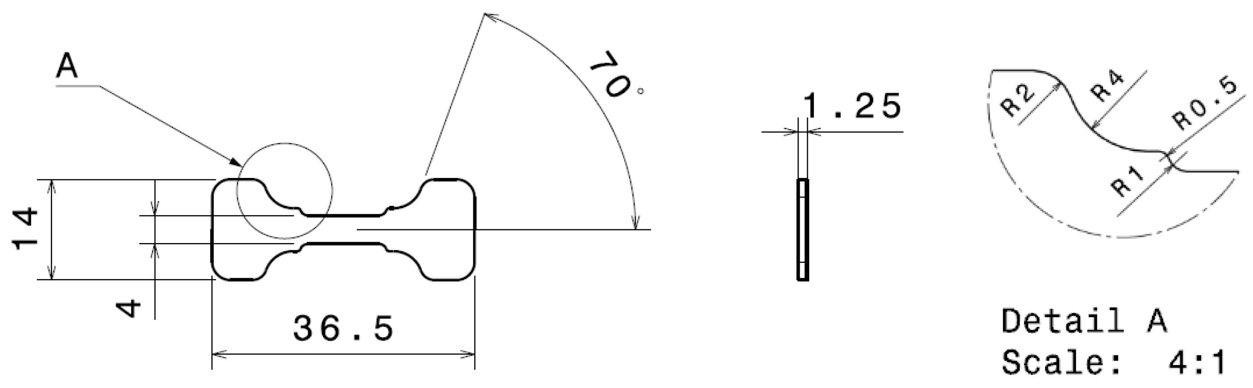
To support the study, the phs-ulstafrom
® 1500 steel material from Voestalpine Stahl GmbH, is cut into given geometries as shown in
Figure 1 with a water-jet. The double-shouldered dog-bone specimens with the gauge length of 10 mm are prepared by taking into account for the gripping force. The specimens are prepared to mount on to the slotted grips, as suggested in the method described in the work from Lefford N. et al. [
9], and the applied force transfers to specimens through the tapered sections of the specimens.
The damping materials, copper (3M™ 1194) and acrylic tape (3M™ 4910 VHB) were placed at the contact surface between the cone and the sleeve so that the hard metal-to-metal contact can be softened. The copper tape and the acrylic tape were selected to distinguish different characteristic damping behaviour. The size of damping materials are 6 mm × 15 mm (L × W) with 1 mm thickness. In the conducted study, a total six strips of tapes are attached to the contact surface leading to a damped contact surface of 540 mm2. As a reference, the dynamic tests without damping material are also performed.
3. Results and Discussion
3.1. Slack Adaptor
The inherent difficulty of dynamic testing at intermediate strain rate is associated with inertia effects and stress wave propagation. Several authors have addressed these problems and have proposed different solutions. For example, Boyce B.L. and Dilmore M.F. [
1] studied the strain rate sensitivity of steels at the strain rates from 0.0002 s
−1 to 200 s
−1. They mitigate oscillations on the force measurement by a custom-designed load cell with a biaxial strain gauge. The threaded cylindrical tensile specimen can be attached directly to the load cell. They found out that the amplitude of the oscillations compared to a quartz load cell could be reduced by up to 50%. Furthermore, the dynamic impulse from load introduction device can excite the test system at its natural frequency. Xiao X. [
7] investigated the effect of the natural frequency of the testing system (a servo-hydraulic machine) with a slack adaptor and found that the amplitude of the system ringing is determined by the natural frequency. Thus, a lightweight grip system is suggested to mitigate the system ringing in force measurements.
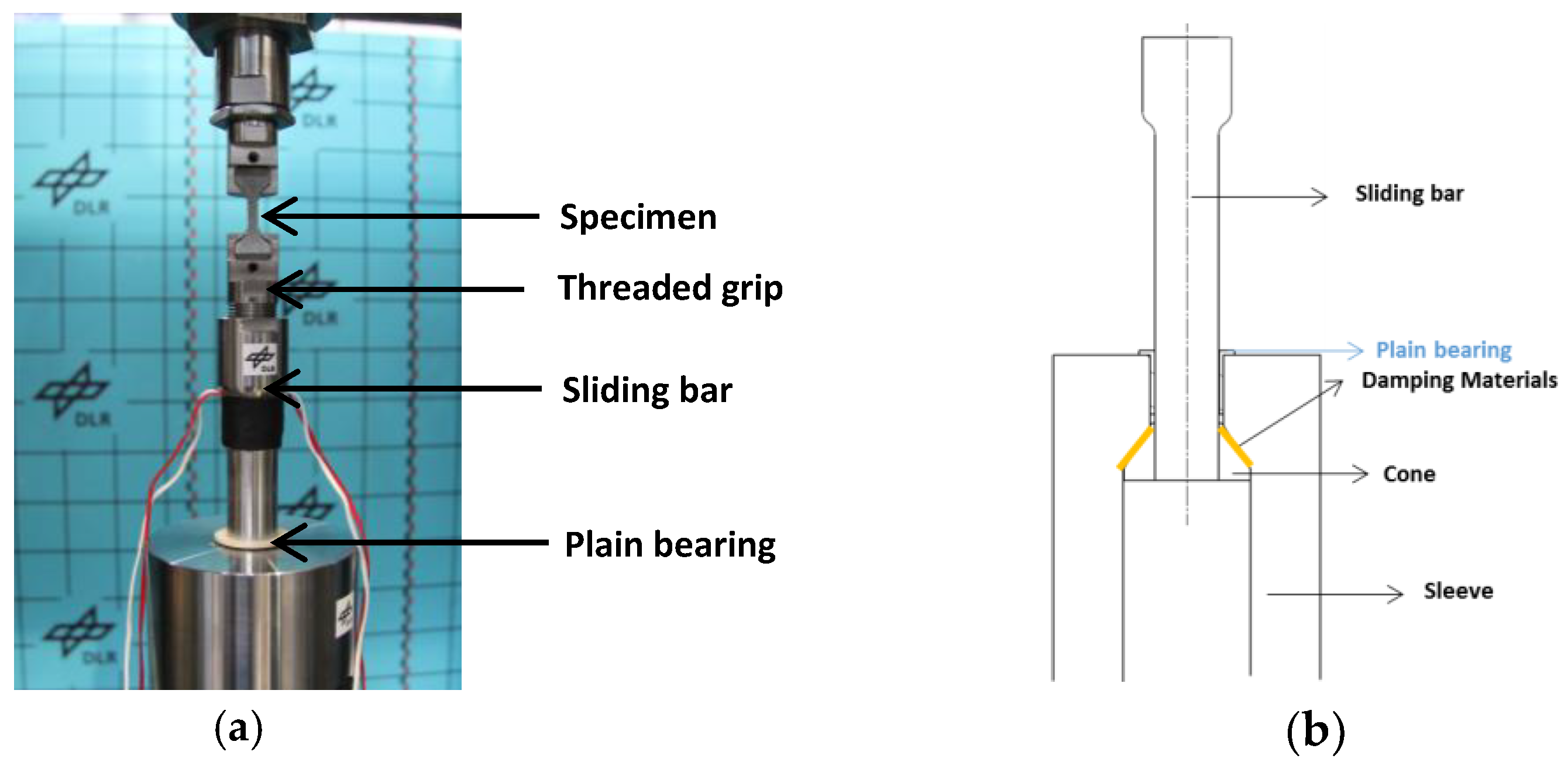
With consideration of existing techniques, a new slack adaptor is designed to produce high-quality results with a high-speed servo-hydraulic machine. The sliding bar is assumed as a spring in the design process, and a stiffness-to-weight ratio of the load introduction device is optimised with a parametric study of spring stiffness (
K). As a result, a threaded grip mechanism is implemented to reduce the weight of the grip system as shown in
Figure 2a. The reduction of the grip weight using a threaded grip system can also be found in [
9,
10,
11] to minimise the inertial effect on force measurements, which results in increasing the test system’s natural frequency. Furthermore, a plain bearing as shown in
Figure 2b is inserted in the slack adaptor to improve an axial alignment (as a lateral constraint) between the loading direction and the specimen.
3.2. System Ringing
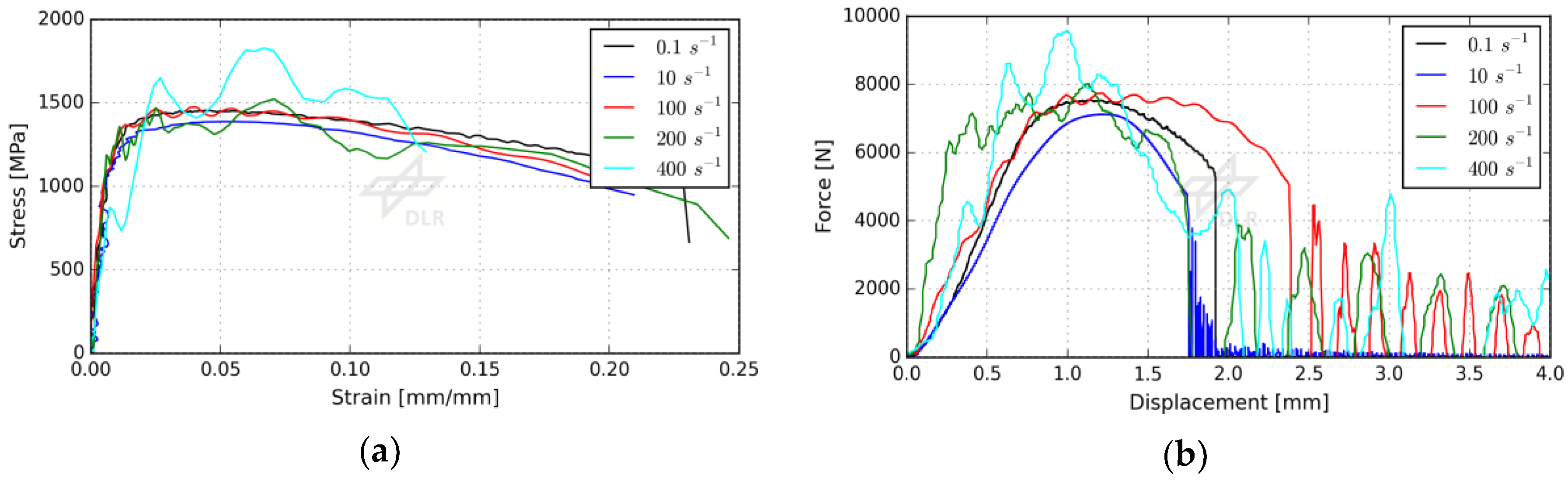
Figure 3a shows that the dynamic tensile stress-strain data at different strain rate levels from quasi-static (0.1 s
−1) to dynamic (400 s
−1) without damping. The raw force signals (no filter is applied) from the load cell are used to calculate the engineering stress, and the strain is extracted from the virtual extensometer from DIC measurements (a gauge length = 6 mm). The 0.2% yield strength and the ultimate tensile strength at strain rate of 0.1 s
−1 are found to be 1094.8 ± 107.5 MPa and 1440.5 ± 18.3 MPa, respectively. The results from the quasi-static condition are compared to the result from data sheet provided by the manufacturer [
12] so that the influence of the specimen geometry can be confirmed. The yield strength is slightly increased with increasing strain rates while the Young’s modulus remains almost the same. It should be noted that the main objective of this work is to obtain an insight of how the load introduction device influences force signals rather than dynamic material characterisations of the steel. Thus, the details of material properties will not be discussed in the current work.
The characteristic features from theses tensile results are the amplitude of the oscillation, which is increased with increasing strain rates. The undesired oscillation hinders the precise determination of the exact yield strength or ultimate tensile strength from measured stress-strain data. It is not clear if the variations are due to specimen-to-specimen scatter or to the oscillations. Furthermore, the distortions of the force signals can be clearly observed from force-displacement data as shown in
Figure 3b. The unacceptable oscillations in force measurements are observed from a nominal strain rate of 100 s
−1, and the amplitude of the oscillations significantly increased at higher strain rates.
The inertial effect known as system ringing is one of the major obstacles to obtain the true dynamic material properties at intermediate strain rates. The load introduction technique associated with the slack adaptor can produce a sudden dynamic impulse in recorded load cell signals. When the load is introduced to the specimen, the high amplitude stress waves are generated in the test system, and it results in the high oscillations on force measurements at the natural frequency of the system. As a result, the identification of the actual stress-strain response from the measured mechanical responses is problematic [
13,
14]. A data analysis of experimental results requires a careful interpretation of results in order to mitigate the challenge.
3.3. The Influence of Damping Material
The use of the damping in the onset of the load train is recommended in references [
8,
13] to mitigate the system ringing since the influence of the inertial effect is inevitable at intermediate strain rate testing. Two different types of damping materials, the copper and the acrylic tape, respectively, are used with the same contact surface area to eliminate the influence of dimensions, and to soften the hard metal-to-metal contact in the slack adaptor.
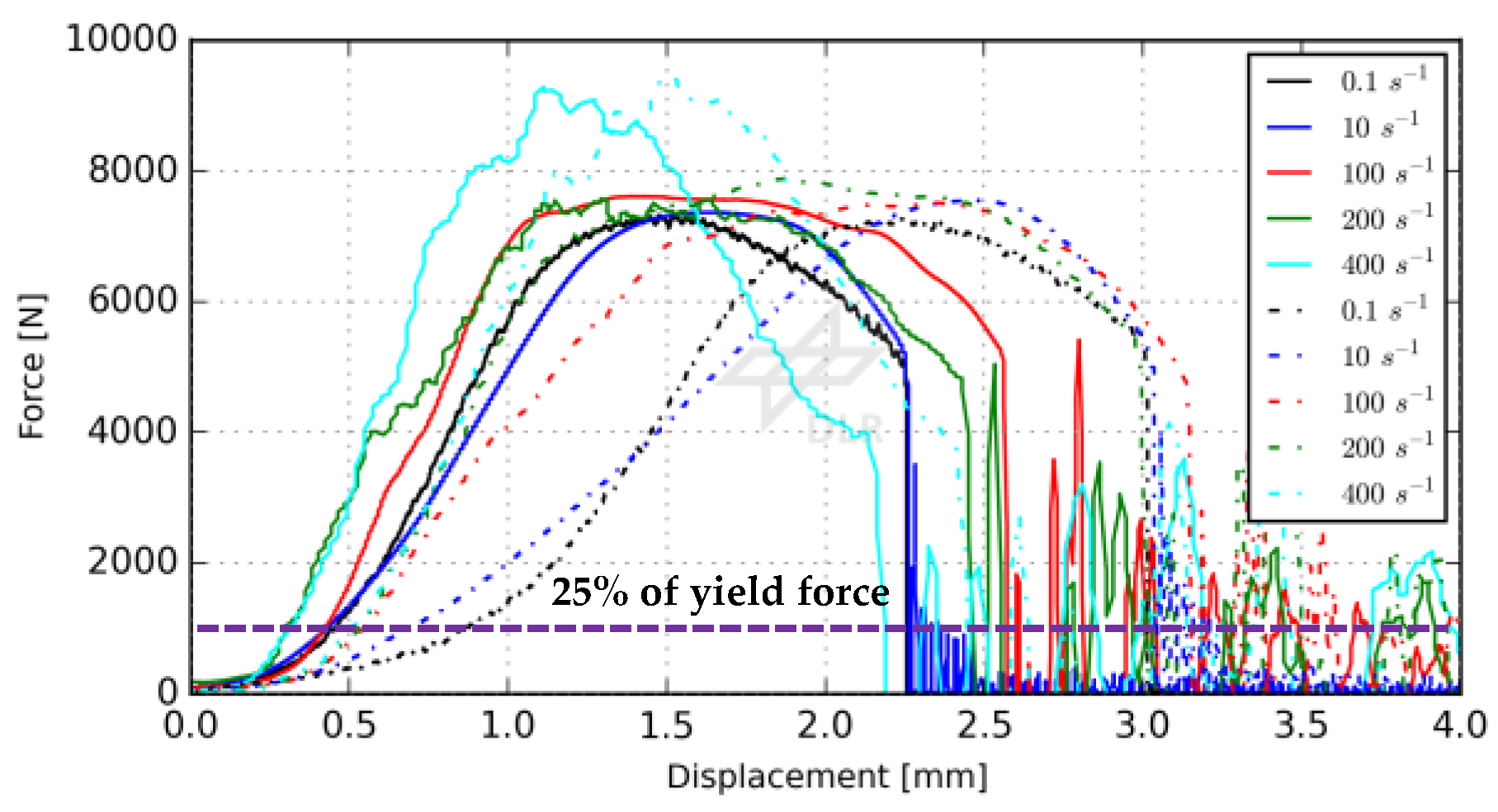
Figure 4 shows that dynamic tensile force-displacement data at various strain rate levels with the copper and the acrylic tape. The displacement from the actuator is used to investigate the effects of damping in terms of a load introduction rate. The slope of the curves (force gradient) represents how the load is introduced. The force gradient becomes smoother in both damping cases in comparison with undamped testings (refer to
Figure 3).
The load introduction rate is controlled by the damping material, which prevents the direct hard contact in the slack adaptor. It is observed that the change of the force gradient is more pronounced in the case of the acrylic tape compared to the copper tape. A smoother transition of the force gradient demonstrates that the acrylic tape is deformed plastically due to its low strength (tensile strength = 690 kPa). Thus, it can absorb the impact energy by the plastic deformation and therefore allow the slow rate of load introduction. On the other hand, the force gradient with the copper tape relatively shows a linear behaviour throughout testings. This result indicates that the energy absorption by the copper tape may be still within the elastic region, which has to be investigated more precisely in another test campaign. Also, a sudden force gradient change in testing with the acrylic tape at strain rates from 10 s
−1 to 100 s
−1 can be observed. A possible reason for this behaviour is that the acrylic tape has a different deformation mechanism due to its strain rate sensitivity. In addition, the SAE standard suggests the damping related effect should be completed before the applied force reaches 25% of the yielding. According to this criterion, the damping related effect should be finished before the applied force reaches approximately 1430 N, which calculated from the yield stress and the averaged cross-section area (5.2 mm
2). The shifting of the displacement corresponding to the yielding force is caused by the damping material, which is slowing the introduction of the acceleration in the specimen. Hence, this phenomenon results in the reduction of the force gradient. The force gradient at low strain rates (0.1 and 10 s
−1) using the acrylic tape is still slightly increasing. Thus, this result indicates that the acrylic tape might not be strong enough to fully attenuate shock stress waves at low strain rate. Furthermore,
Figure 5a shows the tensile results using damping materials and undamped testings at strain rate of 0.1, 100 and 400 s
−1. It can be said that stress-strain curves are very similar and almost free of oscillations up to 200 s
−1. High amplitudes oscillations at strain rate of 400 s
−1 are superposing the measurement. This result reveals that both damping materials can generate similar stress-strain data even though the shape of the load introduction differs.
Another important aspect using damping in the slack adaptor is the time required to achieve the constant strain rate. For example,
Figure 5b shows the displacement-time data at strain rates of 100 s
−1 and 200 s
−1, and the DIC measurements are used to plot the displacement-time data. Hence, the slope of curves can be found and therefore the influence of the applied velocity/strain rate on the specimen can be defined. The time required for the specimen to reach the constant strain rate is extended when the acrylic tape is used. On the other hand, using copper tape in the tests enables to rapidly apply the constant velocity to the specimen, which shows a similar manner to the reference. The amount of the strain before reaching the constant velocity, which is a non-linear portion of the measured curve, should be minimised to validate the dynamic material responses of the material. As stated in [
15,
16], the deformation at a constant strain rate and dynamic stress equilibrium are crucial to obtain accurate stress-strain response under dynamic loading. This possible issue is intensified when the testing material has a low strain at failure as it is difficult, in this case, to achieve a constant strain rate prior to yielding. However, there is no clear limitation on how to produce the desired strain rate to obtain acceptable stress-strain data with damping materials. Therefore, a choice of damping materials should be identified considering at the same time the system ringing and the time required to reach the desired strain rates, which is closely associated to the deformation mechanism of used damping materials.
4. Conclusions
The influence of damping materials on the load introduction device is investigated at different strain rate levels. The experimental results show that both damping materials, the copper and the acrylic tape, are potential candidates for mitigating unacceptable oscillations from measured force signals at intermediate strain rates in comparison to undamped testing. However, it is still difficult to conclude, which types of damping materials are more efficient. A selection of proper damping materials and their associated limitations to produce a constant strain rate is still to investigate. Although a soft contact with the acrylic tape seems more effective to mitigate the oscillations, a variation of the measured material properties due its strain rate sensitivity is larger than that of metallic materials like the copper tape. It is expected that damping materials from the class of the polymer will exhibit the strain rate dependent material properties like the acrylic tape. Thus, care must be taken in the selection of damping materials of this class.
The further investigations on the effect of damping geometry and material types will continue. To attain such benefits, an analysis of damping materials will be performed by the means of numerical simulations. The results of such investigations will contribute to the guidelines on the choice of suitable damping materials with a well-known dynamic behaviour at desired strain rates/loading cases.

 ,
, 


