A Novel Instrumented Human Head Surrogate for the Impact Evaluation of Helmets †
by
Nicola Petrone
1,*, 
Giovanni Carraro
1,
Stefano Dal Castello
1,
Luca Broggio
1,
Andrey Koptyug
2 and
Mikael Bäckström
2 1
Department of Industrial Engineering, University of Padova, Via Venezia 1, 35131 Padova, Italy
2
SportsTech Research Centre, Mid Sweden University, Akademigatan 1, 83125 Ӧstersund, Sweden
*
Author to whom correspondence should be addressed.
†
Presented at the 12th Conference of the International Sports Engineering Association, Brisbane, Queensland, Australia, 26–29 March 2018.
Proceedings 2018, 2(6), 269; https://doi.org/10.3390/proceedings2060269
Published: 13 February 2018
(This article belongs to the Proceedings of The 12th Conference of the International Sports Engineering Association)
Abstract
:A novel Human Head Surrogate was obtained from available MRI scans of a 50th percentile male human head. Addictive manufacturing was used to produce the skull, the brain and the skin. All original MRI geometries were partially smoothed and adjusted to provide the best biofidelity compatible with printing and molding technology. The skull was 3D-printed in ABS and ten pressure sensors were placed into it. The brain surrogate was cast from silicon rubber in the 3D-printed plastic molds. Nine tri-axial accelerometers (placed at the tops of the lobes, at the sides of the lobes, in the cerebellum and in the center of mass) and a three-axis gyroscope (at the center of mass) were inserted into the silicon brain during casting. The cranium, after assembly with brain, was filled with silicon oil mimicking the cerebral fluid. Silicon rubber was cast in additional 3D-printed molds to form the skin surrounding the cranium. The skull base was adapted to be compatible with the Hybrid-III neck and allow the exit of brain sensors cabling. Preliminary experiments were carried out proving the functionality of the surrogate. Results showed how multiple accelerometers and pressure sensors allowed a better comprehension of the head complex motion during impacts.
1. Introduction
Traumatic Brain Injury (TBI) is one of the most severe outcomes of game accidents in sports, crashes in motor vehicles or blast exposition [1]. Helmet manufacturers, regulatory institutions and scientists have been working since decades towards the improvement of protective devices and the reduction of TBI incidence. Compact lightweight recording and warning systems help to analyze the collisions in active sports, supporting the improvements into injury prevention technologies and equipment: a typical issue is how to link the external sensor data to actual brain injury mechanisms. On the other hand, laboratory testing of helmets, despite established in several standards, is still evolving towards the implementation of multidirectional impacts and the availability of instrumented dummy heads able to detect the degree of protection in these complex cases [2].
Headforms as used in international standards are typically hollow aluminum shells with standardized shape and dimensions, housing a triaxial accelerometer at the nominal head Center of Mass (CoM). An increasing number of works utilize the Hybrid III dummy head for helmet evaluation, mostly due to the connection to the Hybrid II neck that presents a differential flexibility in flexion and extension. Instruments in the H-III dummy head are typically only triaxial accelerometers, with some additional gyros at the dummy CoM.
Very few literature sources can be found regarding the development of biofidelic human head surrogate for use in the field of helmet development. In the first research by Zhang et al. [3] a gel-filled ellipsoidal-shaped physical model was used. The shell cavity was filled with gel through a 32 mm hole made on the bottom side of the model. Four pressure transducers were attached outside the shell and other four were symmetrically distributed about the longitudinal axis of the model in the mid-coronal plane, 35 mm deep into the brain simulant. The transducers managed to catch the intracranial pressure response, but the biofidelity of the model (in terms of head anatomy, skull material properties and meninges replication) was quite poor. Zhu et al. [4], used the same kind of silicone gel (Sylgard® 527 A&B, Dow Corning, Midland, MI, USA) and an egg-shaped skull/brain surrogate was exposed to blast overpressure in a shock tube environment. Pressures within the shock tube and the surrogate were recorded throughout the event using an optic pressure gauge placed inside the model. In neither of the cases, there was any intention to recreate an anatomically faithful surrogate and the anatomical details of the human head were admittedly neglected. A third study was carried out by Taha et al. [5], investigating the effects of soccer heading on the brain structure. A head surrogate was created, again, by filling a hollow plastic skull (printed out Acrylonitrile Butadiene Styrene) with ultrasound gel12. This solution not only is anatomically inaccurate but also ignores the relative movement between the brain and the skull as well as the influence of the intermediate tissues between them. One triaxial accelerometer (model 356A67, manufactured by PCB Piezoelectronics, Depew, NY, USA), was placed inside the gel roughly at the centre of gravity of the skull (7 cm from the foramen magnum) assuming that the accelerations obtained from the accelerometer represented the brain acceleration. In 2015, Awad et al. [6] developed a more sophisticated head model while investigating blast-induced mild traumatic brain injuries. In this case four pressure transducers (one in the frontal lobe, one in the occipital lobe, one in the temporal lobe and one between the two hemispheres towards the right side) were embedded in the surrogate brain, while one accelerometer (only) was attached to the brain surface. The main focus of the work was nevertheless the design of a reliable airdriven shock tube rather than the design of the brain-skull complex itself, exactly as it was by Zhu et al. [4]. In addition, the standardization process for the brain molding or the consistency of the used geometries was not explicitly mentioned (no information about separation between lobes, cerebellum presence, etc.).
The most advanced Human Head surrogate is the one developed by Freitas et al. [7] for use in military helmets blast investigations. This human head surrogate is based on refreshed human craniums (dehydrated human bone from donors, rehydrated by soaking for 30’ in a Shellac solution) and surrogate materials representing human head soft tissues such as the skin (5–7 mm of Perma-gel), dura (0.5 mm silicon membrane), and brain (Perma-gel mixed to iron ). Sensors embedded in the human head surrogates allow for direct measurement of intracranial pressure (four pressure sensors in the brain), cranial strain (12 strain rosettes), and skull (triaxial accelerometer at the hard palate) and helmet acceleration.
Aim of the present work is to introduce the novel Instrumented Human Head Surrogate (IHHeadS_1) developed at Mid Sweden University, Ostersund-SWE in collaboration with University of Padova-IT for the biofidelic impact investigation of helmets and the study of brain injury mechanisms.
2. Materials and Methods
2.1. Definition of Surrogate Head Geometry
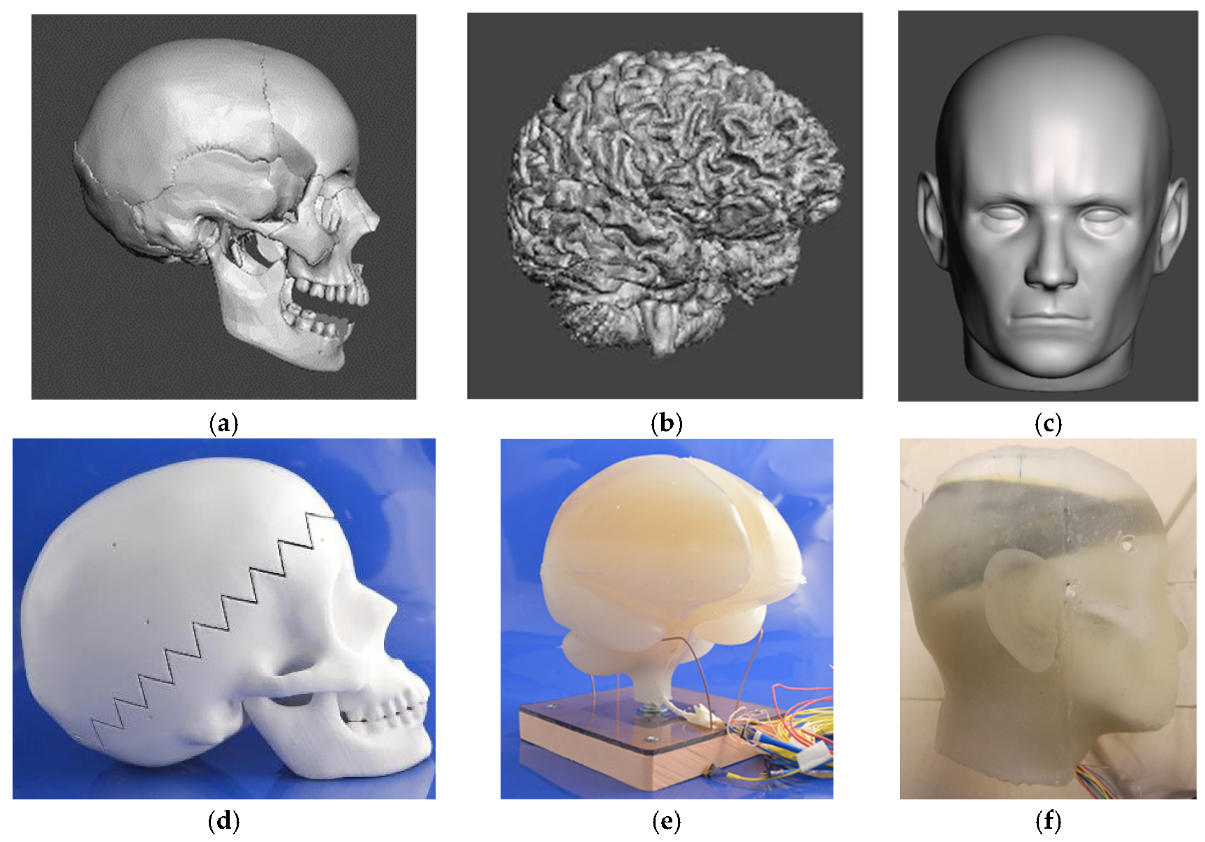
The head geometry was obtained from the MakerBot® Industries (Brooklyn, NY, USA) crowd-sourced website Thingiverse.com [8]: this data were created starting from human body polygon data extracted from MRI scans. Original geometries were quite irregular and some elements were partially detached or even floating. Together with the correction of the mesh flaws, a simplification process of skull and brain geometry was carried out.
The main goals of the skull model simplification were: (i) making sure that each single part was attached to the main body; (ii) closing each hole except for the foramen magnum; (iii) shaping the orbits in order to possibly accommodate some surrogate eyes; (iv) flattening the bottom part of the skull anticipating the design of the head-neck connection; (v) creating a functional joint between the skull and the mandible; (vi) ensuring the symmetry of the model. Each operation was performed keeping both a high level of anatomical detail (especially in the interior part, where the brain need to be accommodated) and the adequate simplicity to facilitate parallel FE analysis.
With the brain geometry, all artifacts of the brain model were manually removed using specific tools by Meshmixer sw. In this case, the simplification process aimed to (i) restore the anatomical separation between the hemispheres and between hemispheres and cerebellum; (ii) guarantee the brain symmetry; (iii) thicken the brain stem for allowing the accelerometers cable to pass-through; (iv) fitting the brain shape to the skull one. The representation of the brain sulci was ignored to allow a simpler and more robust demolding phase. Results of this work can be seen from the comparison of Figure 1a,d for the skull, Figure 1b,e for the brain model.
2.2. Construction of Skull, Brain and Skin
The material adopted for the skull was ABS plus-P430 manufactured by Stratasys Ltd. (Eden Prairie, MN, USA). A 3D printer based on FDM technology was used to produce both the skull and the molds for the brain and the skin. In the first build (about 33 h) the bottom skull and the mandible were realized, while the upper part was printed in about 24 h (Figure 1d). Once the support material was removed, the inner surface of the skull was smoothed by hand using sandpapers of different grit sizes removing little defects and preparing the inner surface for the coating. The whole skull was then double coated with white spray paint, making sure that the inner surface was perfectly smooth and ready to accommodate the pressure transducers and the floating brain.
The brain molds were printed in three steps for a total build time of 65 h. The molds were hence manually sandpapered, three times coated and finally painted to obtain the smoothest possible brain surface. Given the large variability in literature data about brain properties, a material that could be tuned according to necessities and molding outcomes was adopted. The choice was the silicone rubber Platsil-Gel 01-30 A + B, manufactured by Polyconform GmbH (Dusseldorf, D). The brain was molded pouring the rubber on the molds in three different stages corresponding to the layers of application of accelerometers in the brain, with molds placed upside down, starting from the brain top. The result was a complete brain with separation of hemispheres and cerebellum having the sensors cables coming out via the brain stem (Figure 1e).
The skin geometry was retrieved from the same source (Figure 1c) and underwent a simplification process to be compatible with the skull outer surface: a further set of molds was designed to prepare the negative mold corresponding to the outer skin surface and the positive mold for the inner skin surface. Silicone rubber Platsil-Gel 01-30 in different combination of components was used to mimic the skin properties as found from literature. The two halves of the skin mask were applied to the skull to obtain the complete IHHeadS_1 and make it available for the impact tests (Figure 1f).
2.3. Sensorization of Brain and Skull
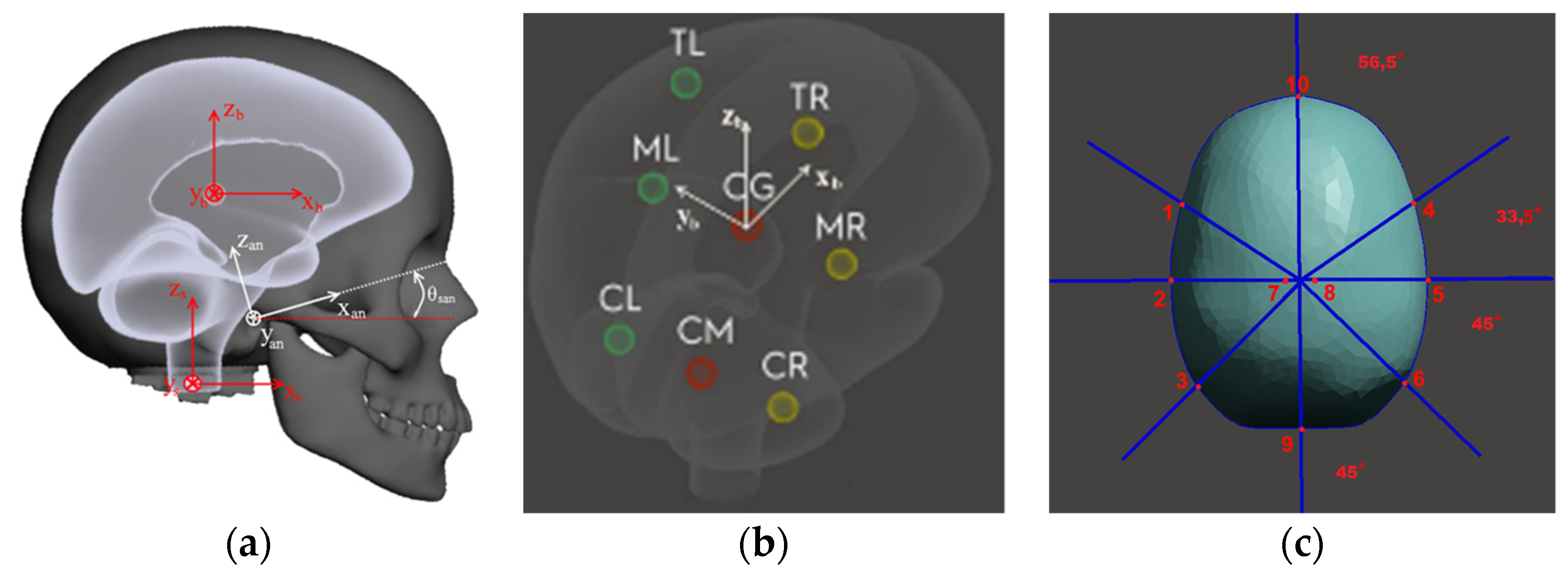
Nine triaxial accelerometers (ADXL377, Analog Devices (Norwood, MA, USA), ±200 g) were placed on the brain in order to explore its local behavior during impacts. A stack of two biaxial gyrometer chips (LPY4150AL-pitch & yaw, and LPR4150AL-pitch &roll, both ±1500 deg/s, ST Microelectronics-Geneve, CH) and one accelerometer were placed on the center of gravity of the brain, as localized by a specific tool in Meshmixer sw. Two accelerometers (ML and MR) were placed aside the CG at 20 mm from the side surface; two accelerometers (TL and TR) were positioned on the same coronal plane of CG, 15 mm from the top rubber surface. Finally, three accelerometers (CL, CM and CR) were located ideally on cerebellum center of mass and to its sides, to track its motion separately from the rest of the brain Figure 2b. Ten pressure sensors (Sencera STD 100 PSIA, Taipei, Taiwan) were applied to the skull as visible in Figure 2c. Sensors were embedded in cavities drilled in the skull and disposed circumferentially on a transverse plane located close to the brain CoM. Two sensors were also placed close to the skull apex facing the top portions of the two brain lobes.
2.4. Pilot Tests Setup
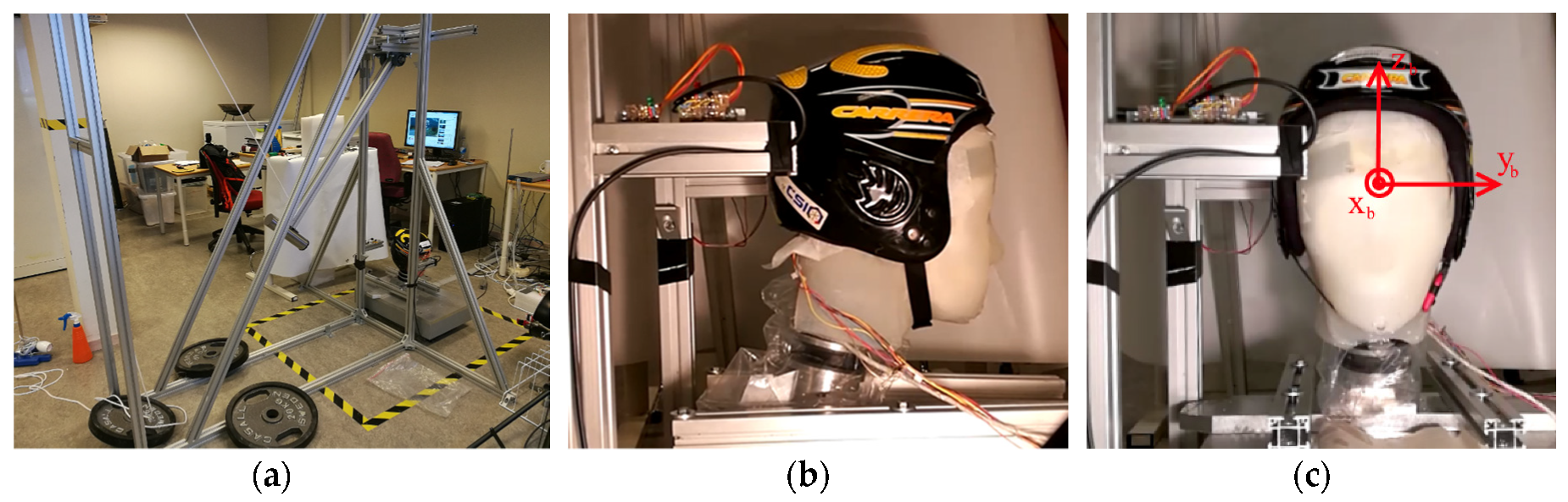
The pendulum developed for the application of impacts to IHeadS_1 (Figure 3a) enabled to impact the head surrogate with an impactor similar to the one used by Nahum [9], and with impact energy up to 100 J. The IHeadS_1 connected to the H-III neck was mounted on a Kistler force platform and impacts were performed from the Back, the Side and the Front. For comparison, impacts were also performed on a Hybrid III head wearing the same helmets and equipped at the CoM with the triaxial accelerometer and the same set of gyro meters.
3. Results
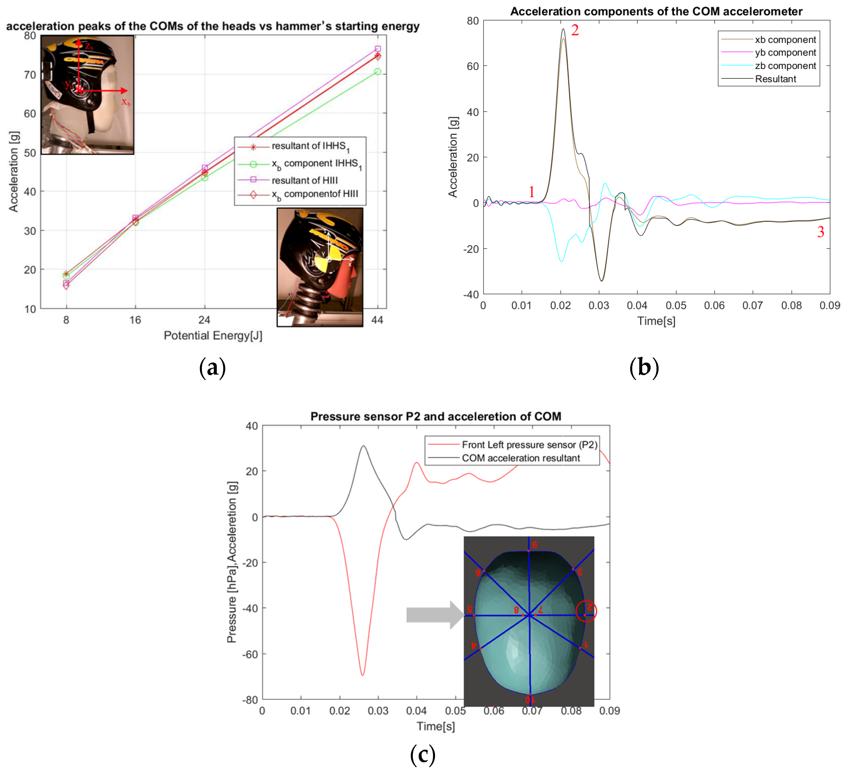
Impact peak resultant accelerations, as recorded in the IHHeadS_1 brain CoM and in the HIII dummy, resulted to be in good agreement at increasing impact energy (Figure 4a). The detail of the brain acceleration in three direction is appreciable in Figure 4b, for a 44 J back impact, where the resultant takes the sign of the larger magnitude component (xb). Similar agreement between IHHeadS_1 brain CoM and HIII was found in the Front and Side impacts, showing the ability of IHHeadS_1 in matching the well-known behavior of Hybrid III dummy head.
The added value of IHHeadS1 is the large amount of additional information obtained from brain accelerometers, brain gyro meters and pressure sensors that enable the investigation of the brain internal behavior. The pressure wave recorded in the synthetic cerebral fluid at the skull internal side opposite to the right impact location is reported in Figure 4c: as the skull is accelerated to the left, the left side pressure sensor (nr.2 in Figure 2c) shows a synchronous pressure drop.
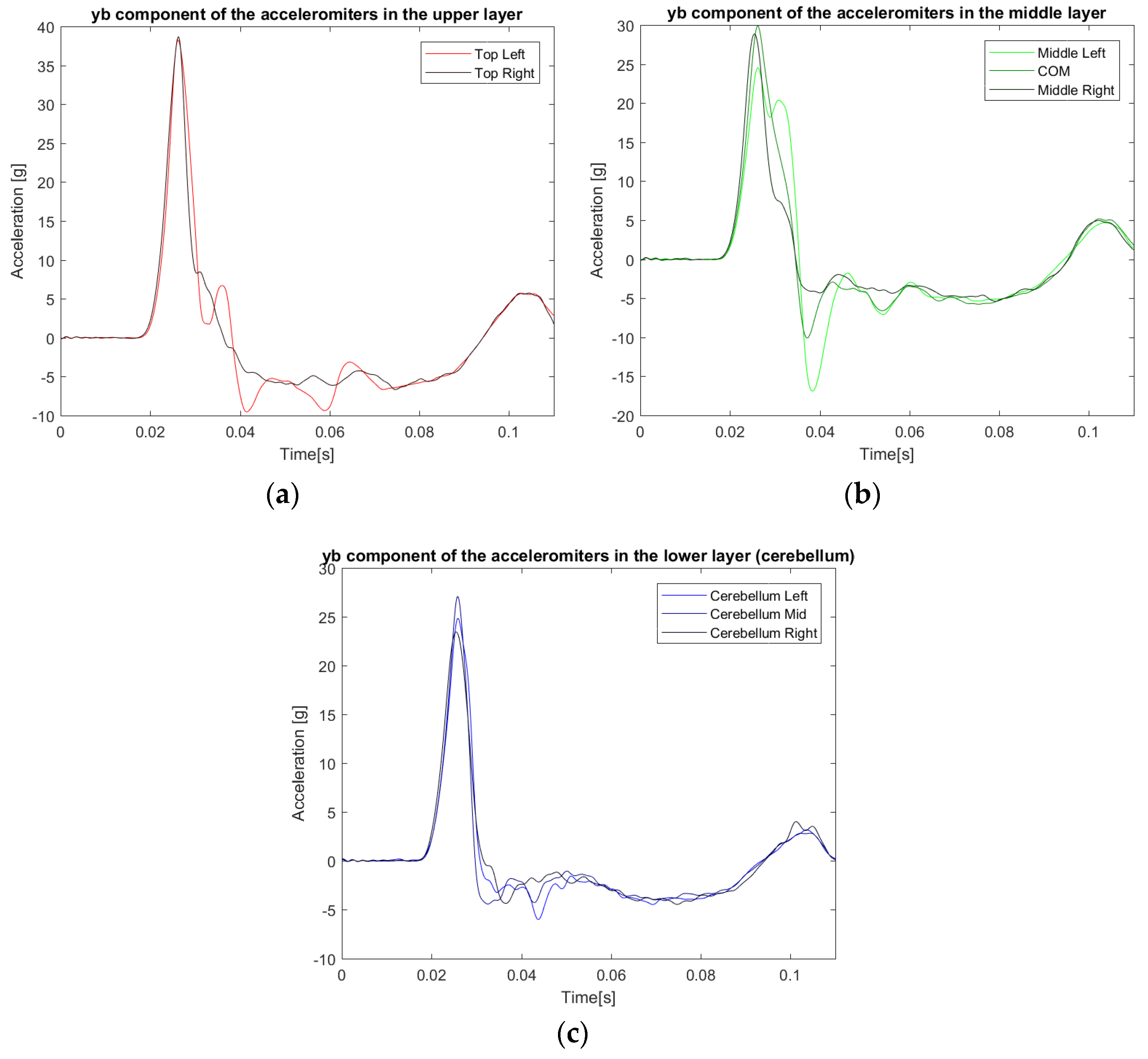
The analysis of top, middle and lower (cerebellum) side accelerations in Figure 5, can give a deeper insight to the brain behavior during such a lateral impact (Figure 3c), taken as an example: it can be noticed how the right accelerations are consistently smoother, whereas middle and left ones show undamped vibrations that correspond to the brain wobbling behavior. Peak values are considerably decreasing in the top-down direction; in Figure 5b, the increasing delay between right, middle (CoM) and left side of the brain in reaching the peaks is evident, as the increasing amount of wobbling.
4. Discussion
IHHeadS1 is a synthetic, 3D printed surrogate head. It is therefore reproducible and can be shared among different laboratories. Its biofidelity is larger than headforms and HIII dummy heads. Due to its large number of sensors, it can also give insight in the performance of emerging technologies for protection against multidirectional impacts. Further work is going on to optimize the surrogate reliability and to validate the head behavior with and without helmets.
5. Conclusions
An instrumented human head surrogate IHHeadS1 was developed for use in the experimental evaluation of helmets degree of protection against impacts. Being a synthetic, 3D printed surrogate head it is widely reproducible and can be shared among different laboratories: it is also cheaper and ethically preferable to surrogates based on rehydrated human bone. Its biofidelity is larger than standard headforms and HIII dummy heads, but its overall behavior is comparable. Due to its large number of sensors, it will enable a deeper insight into the brain/skull interactions and in the performance of emerging protection technologies against multidirectional impacts.
Conflicts of Interest
The authors declare no conflict of interest.
References
- Gessel, L.M.; Collins, C.L.; Dick, R.W. Concussions among United States high school and collegiate athletes. J. Athl. Train. 2007, 42, 495–503. [Google Scholar] [PubMed]
- Aare, M.; Halldin, P. A new laboratory rig for evaluating helmets subject to oblique impacts. Traffic Inj. Prev. 2003, 4, 240–248. [Google Scholar] [CrossRef] [PubMed]
- Zhang, J.; Pintar, F.A.; Yoganandan, N.; Gennarelli, T.A.; Son, S.F. Experimental study of blast-induced traumatic brain injury using a physical head model. Stapp Car Crash J. 2009, 53, 215–227. [Google Scholar] [PubMed]
- Zhu, F.; Wagner, C.; Leonardi, A.D.C.; Jin, X.; VandeVord, P.; Chou, C.; Yang, K.H.; King, A.I. Using a gel/plastic surrogate to study the biomechanical response of the head under air shock loading: A combined experimental and numerical investigation. Biomech. Model. Mechanobiol. 2012, 11, 341–353. [Google Scholar] [CrossRef] [PubMed]
- Taha, Z.; Hassan, M.H.A.; Hasanuddin, I.; Aris, M.A.; Majeed, A.P.A. Impact-absorbing materials in reducing brain vibration caused by ball-to-head impact in soccer. Procedia Eng. 2014, 72, 515–520. [Google Scholar] [CrossRef]
- Awad, N.; El-Dakhakhni, W.W.; Gilani, A.A. A physical head and neck surrogate model to investigate blast-induced mild traumatic brain injury. Arab. J. Sci. Eng. 2015, 40, 945–958. [Google Scholar] [CrossRef]
- Freitas, C.J.; Mathis, J.T.; Scott, N.; Bigger, R.P.; MacKiewicz, J. Dynamic Response Due to Behind Helmet Blunt Trauma Measured with a Human Head Surrogate. Int. J. Med. Sci. 2014, 11, 409–425. [Google Scholar] [CrossRef] [PubMed]
- Human Head. Available online: https://www.thingiverse.com/thing:172348 (accessed on 12 February 2018).
- Nahum, A.M.; Smith, R.; Ward, C.C. Intracranial Pressure Dynamics during Head Impact (No. 770922); SAE Technical Paper; Nahum, A.M., Smith, R., Raasch, F., Eds.; SAE International: Warrendale, PA, USA, 1977. [Google Scholar]
Figure 1.
(a) Original 3D model of the skull from MRI database; (b) original 3D model of the brain from MRI; (c) 3D model of the head used for the molds; (d) 3D ABS printed version of the simplified skull with the visible suture for insertion of the sensorized brain; (e) molded version of the simplified brain with lobe separation and cerebellum (sensor cables coming out from the brain stem); (f) complete head with sensorized brain inside and the outer skin.

Figure 2.
(a) Head and brain systems of reference; (b) location of 9 sensors in the brain; (c) disposition of pressure sensors in the skull.
Figure 2.
(a) Head and brain systems of reference; (b) location of 9 sensors in the brain; (c) disposition of pressure sensors in the skull.

Figure 3.
Pilot tests. (a) Impact pendulum and experimental setup; (b) back impact on surrogate IHHeadS_1; (c) right side impact on surrogate IHHeadS_1.
Figure 3.
Pilot tests. (a) Impact pendulum and experimental setup; (b) back impact on surrogate IHHeadS_1; (c) right side impact on surrogate IHHeadS_1.

Figure 4.
Pilot tests results. (a) Comparison between IHHeadS_1 and HIII in back impacts tests; (b) Example of three acceleration components at the brain CoM after a 44 J back impact test; (c) CoM acceleration and fluid depression wave during right side impact on surrogate IHHeadS_1 at 16 J (top view).

Figure 5.
Results of a right side impact at 16 J on surrogate IHHeadS_1 in lateral yb direction. (a) Top brain accelerometers; (b) middle brain accelerometers; (c) cerebellum accelerometers.
Figure 5.
Results of a right side impact at 16 J on surrogate IHHeadS_1 in lateral yb direction. (a) Top brain accelerometers; (b) middle brain accelerometers; (c) cerebellum accelerometers.

Publisher’s Note: MDPI stays neutral with regard to jurisdictional claims in published maps and institutional affiliations. |
© 2018 by the authors. Licensee MDPI, Basel, Switzerland. This article is an open access article distributed under the terms and conditions of the Creative Commons Attribution (CC BY) license (https://creativecommons.org/licenses/by/4.0/).
Share and Cite
MDPI and ACS Style
Petrone, N.; Carraro, G.; Castello, S.D.; Broggio, L.; Koptyug, A.; Bäckström, M. A Novel Instrumented Human Head Surrogate for the Impact Evaluation of Helmets. Proceedings 2018, 2, 269. https://doi.org/10.3390/proceedings2060269
AMA Style
Petrone N, Carraro G, Castello SD, Broggio L, Koptyug A, Bäckström M. A Novel Instrumented Human Head Surrogate for the Impact Evaluation of Helmets. Proceedings. 2018; 2(6):269. https://doi.org/10.3390/proceedings2060269
Chicago/Turabian StylePetrone, Nicola, Giovanni Carraro, Stefano Dal Castello, Luca Broggio, Andrey Koptyug, and Mikael Bäckström. 2018. "A Novel Instrumented Human Head Surrogate for the Impact Evaluation of Helmets" Proceedings 2, no. 6: 269. https://doi.org/10.3390/proceedings2060269