Dynamic Optimization of the Golf Swing Using a Six Degree-of-Freedom Biomechanical Model †


Systems Design Engineering, University of Waterloo, 200 University Ave. W, Waterloo, ON N2L 3G1, Canada
*
Author to whom correspondence should be addressed.
†
Presented at the 12th Conference of the International Sports Engineering Association, Brisbane, Queensland, Australia, 26–29 March 2018.
Proceedings 2018, 2(6), 243; https://doi.org/10.3390/proceedings2060243
Published: 13 February 2018
(This article belongs to the Proceedings of The 12th Conference of the International Sports Engineering Association)
Abstract
:Advances in golf club performance are typically based on the notion that golfer biomechanics do not change when modifications to the golf club are made. The purpose of this work was to develop a full-swing, forward dynamic golf drive model capable of providing deeper understanding of the interaction between golfer biomechanics and the physical properties of golf clubs. A three-dimensional biomechanical model of a golfer, a Rayleigh beam model of a flexible club, an impact model based on volumetric contact, and a spin-rate dependent aerodynamic ball flight model are used to simulate a golf drive. The six degree-of-freedom biomechanical model features a two degree-of-freedom shoulder joint and a pelvis to model the X-factor. It is driven by parametric joint torque generators designed to mimic muscle torque production, which are scaled by an eccentric-concentric torque-velocity function. Passive resistive torque profiles fit to experimental data are applied to the joints, representing the resistance caused by ligaments and soft tissues near the joint limits. Using a custom optimization routine combining genetic and search-based algorithms, the biomechanical golf swing model was optimized by maximizing carry distance. Comparing the simulated grip kinematics to a golf swing motion capture experiment, the biomechanical model effectively reproduced the motion of an elite golf swing.
1. Introduction
Due to its predictive capabilities, a three-dimensional (3D) dynamic simulation of a golf drive is a valuable asset for providing insights on optimal golfer biomechanics and golf club behavior. Until recently, forward dynamic golf swing models have been limited to two-dimensions, i.e., the motion of the golf shaft has been constrained to a single plane [1]. In 2009, MacKenzie and Sprigings [2] published the first 3D forward dynamic model of the golf swing, motivated by evidence that the golf swing is not planar [3]. Their four degree-of-freedom (DOF) rigid-body biomechanical model was actuated by parametric muscle torque generators designed to mimic biomechanical joint torque production [4]. The biomechanical model was paired with a discretized flexible shaft comprised of four rigid sections interconnected by rotational spring-damper elements to simulate shaft deflection during the downswing. To validate the model, the simulated kinematics were regressed onto motion capture data of a “category-1” golfer using a genetic algorithm. Optimization of the golf swing was then performed by maximizing the horizontal clubhead speed at impact.
Balzerson et al. [5] improved the model of MacKenzie and Sprigings, supplementing the biomechanical model with experimental passive joint torque profiles from literature and using an analytical flexible beam based on Rayleigh beam theory to model the golf shaft. Developed using the multibody software MapleSim (Maplesoft, Waterloo, ON, Canada), their golf swing model was combined with a momentum-based free-body impact model and a spin-rate dependent aerodynamic ball flight model to enable biomechanical optimization through maximization of carry distance as opposed to clubhead speed. Although providing a notable improvement to the model and optimization scheme of MacKenzie and Sprigings, the shaft deflection results of Balzerson et al. displayed spurious oscillations that were inconsistent with experimental measurements. The oscillations, possibly caused by a lack of damping [5], have since been resolved using an iterated flexible beam component incorporating internal damping, available in the 2016.2 version of MapleSim. The new flexible club model was validated against motion capture data in associated work by McNally et al. [6], showing good agreement with experimental shaft deflection in the full swings of ten elite golfers. In the same work, an analytical impact model based on volumetric contact was integrated with the flexible club and tuned using experimental data.
In addition to upgrading the flexible club and impact with these validated models, a number of biomechanical improvements were made to address the shortcomings of the preceding models: a body segment representing the pelvis has been added to provide insights on the significance of torso-pelvic separation (X-factor), a DOF has been added to the shoulder joint to enable a dynamic swing plane, the backswing has been modelled to overcome shaft initialization issues, and the torque-velocity scaling function has been modified to account for eccentric contractions. It should be noted that this work is an extension of Balzerson et al. and therefore knowledge of the aforementioned models [2,5] is helpful.
2. Methods
2.1. Biomechanical Model Advancements
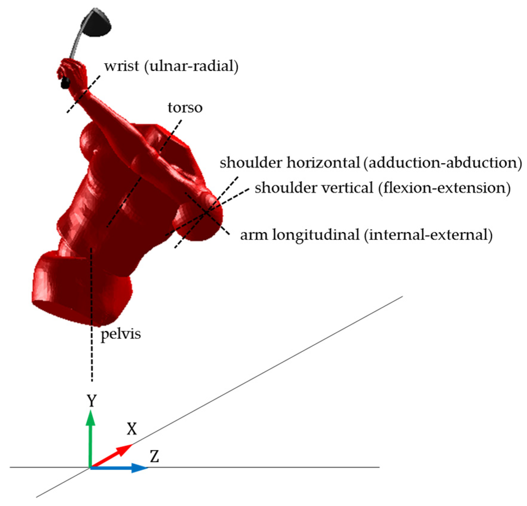
In a study examining the role of upper torso and pelvic rotation in driving performance for golfers of various skill levels [7], it was found that the relative rotation of the upper torso with respect to the pelvis, referred to as the X-factor [8], is correlated with ball velocity (r = 0.54, p < 0.001). Balzerson et al. made an initial step toward modeling the X-factor by including a non-linear passive resistive torque acting on the torso. Correctly modelling the X-factor using a relative angle of separation requires the addition of the pelvis. The pelvis was added to the model via a universal joint, allowing the pelvis to rotate about a vertical axis, while the torso rotates about its own axis tilted forward towards the golf ball. There are no experiments in literature measuring the passive resistance for pelvis rotation relative to the ground, so the torso’s passive torque was also applied to the pelvis.
The preceding models contained a single DOF shoulder joint capable of horizontal adduction. A second axis of rotation has been added, allowing vertical flexion-extension of the shoulder. The biomechanical rotational DOFs are displayed in Figure 1. The DOFs are actuated by the same muscle torque generators used in the preceding models, represented by the following equation:
where is the maximum isometric torque, and are the activation and deactivation time constants, is the total time from the start of the torque generator activation, and is the total time after deactivation. Body segment lengths and inertia parameters were taken from de Leva [9], where the lower trunk segment was used for the pelvis, and the upper and mid trunk segments were combined for the torso. To actuate the vertical DOF of the shoulder, the maximum isometric shoulder torque was decomposed into two components:
where is the maximum isometric shoulder torque, is the horizontal component, is the vertical component, and is the shoulder torque ratio. The r-value effectively controls the plane of the swing.
Sprigings and Neal [4] incorporated the Hill force-velocity relationship into their muscle torque generators by scaling their instantaneous isometric torque using the equation:
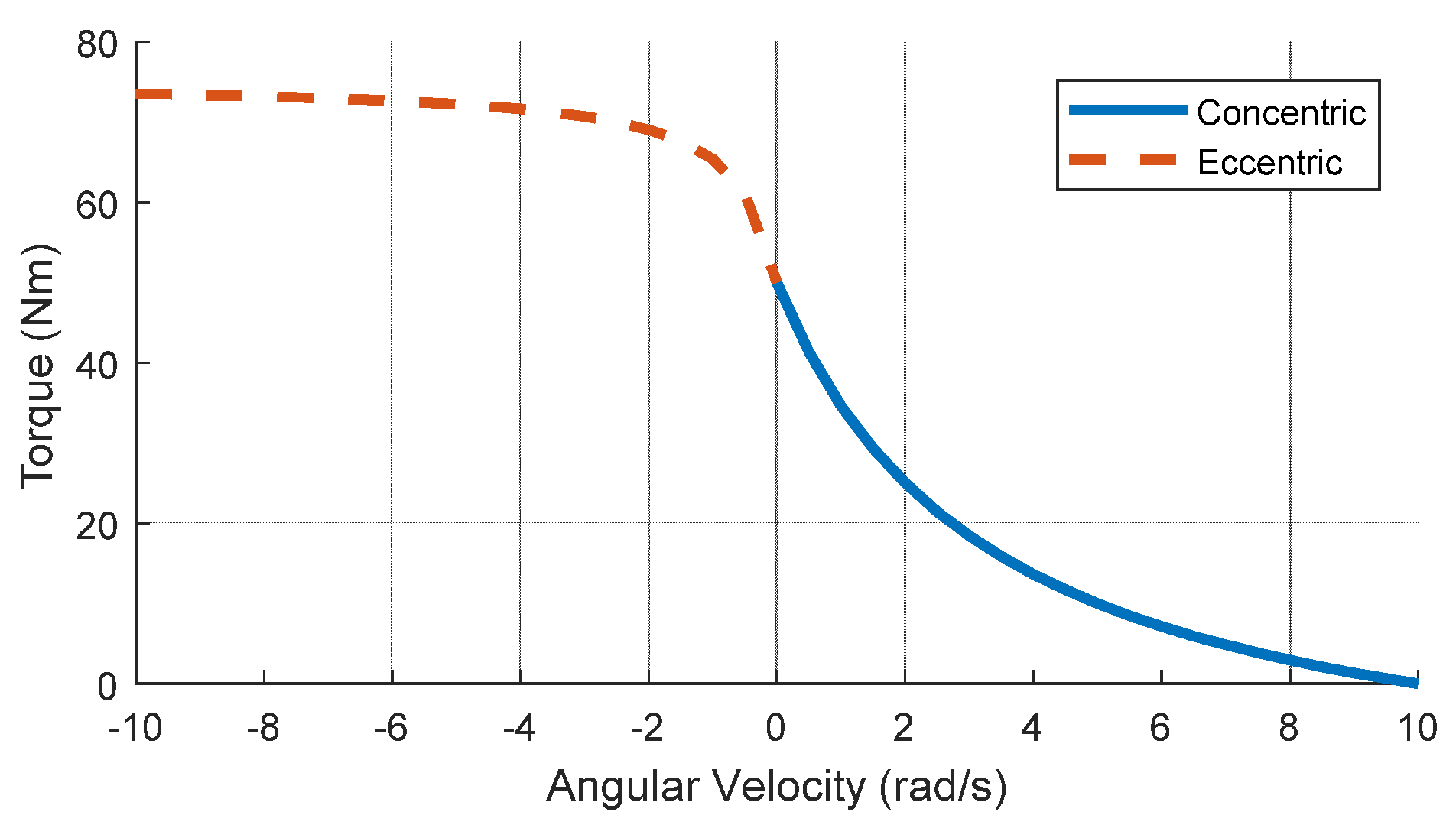
where was the joint’s instantaneous angular velocity, was the joint’s maximum angular velocity, and was a shape factor affecting the curvature. With the incorporation of the backswing into this new model, some of the joints may have a negative angular velocity at the time of activation (i.e., ), potentially creating a singularity as ω approaches −ωmax/Γ. The pioneering experiments of Katz [10] suggest that the force-velocity relationship diverges from Hill’s model when a force greater than isometric tension is applied. The divergence was illustrated by a discontinuity in velocity at the onset of lengthening and an exponential increase in the rate of lengthening with increasing applied force. Van Soest et al. [11] provide a generic equation for the eccentric force-velocity relationship observed in the experiments of Katz. The rotational equivalent of this equation was manipulated to use the same variables as Sprigings and Neal:
where is the slope-factor, defined by van Soest et al. as the ratio between the eccentric and concentric derivatives of force with respect to velocity at isometric force, and is the ratio between the maximum eccentric and isometric force. A slope-factor of 2 and a force ratio of 1.5 was used in this model, matching the values used by van Soest et al [11]. Using a piecewise function, an example torque-velocity scaling profile is shown in Figure 2 for a nominal isometric torque of 50 Nm, a maximum angular velocity of 10 rad/s, and a shape factor of 3. Besides the pelvis, all the torque generators use the same parameters as MacKenzie and Sprigings [2]. The pelvis is more proximal than the torso, so it was given a maximum isometric torque of 250 Nm, 25% greater than the torso, and a maximum angular velocity of 30 rad/s, equal to that of the torso.
2.2. Golf Drive Simulation
The address position (position and orientation of a golfer’s joints before the swing commences) was predetermined. The pelvis and torso angles were taken from mean values in literature [12], and the remaining joint angles were determined by matching the golfer model’s grip position and orientation to the mean grip position and orientation from the motion capture experiment in the associated work of McNally et al. [6]. The golf swing is driven by 12 muscle torque generators—two for each DOF (backswing and downswing). In the preceding models, the golf swing simulation began at the top of the backswing and assumed the shaft initially had no deflection. In real golf swings, the shaft has significant toe-up deflection caused by the quick transition from backswing to downswing. The shaft initialization issue is solved by modelling the backswing. The set of backswing torque generators use the same parameters as those used for the downswing except with negative maximum isometric torques and scaled maximum angular velocities. The maximum angular velocities for the backswing were scaled by a factor of 0.07, and the maximum isometric torques were scaled by a factor of 0.65 to create a realistic 3:1 tempo (duration of backswing to duration of downswing) and swing duration (address to impact) of approximately 1 second. To simulate the shaft deflection and impact, the validated flexible club and impact models described in the work of McNally et al. [6] are used. The simulated launch conditions of the golf ball are recorded shortly after impact, and used to initialize an aerodynamic model [5] that simulates the ball flight.
2.3. Optimization
The optimization variables are the activation and deactivation times of the muscle torque generators, the shoulder torque ratio and a parameter , permitting slight adjustment of the height of the pelvis. is attributed to small variances in knee flexion among golfers. To reduce the size of the solution space, some assumptions were made:
- the torso and shoulder activate and deactivate simultaneously,
- the pelvis, torso, shoulder and arm all activate at t = 0 to initiate the backswing, and
The objective of the biomechanical optimization is to maximize carry distance, measured as the point-to-point distance the golf ball travels in the air. Shots that travel offline are not penalized because it is assumed that the golfer may adjust their alignment such that the same shot lands in the center of the fairway. Rather than defining the initial ball position and forcing the model to make contact, the initial ball position is determined as follows: for each simulated swing, the impact and carry distance are simulated assuming a center-face impact at several points in the swing where the clubhead is within a height achievable using a maximum length tee of 4 inches (101.6 mm). If the model swings above the maximum achievable tee height or too close to the body, the swing is discarded. Moreover, if the clubhead touches the ground, or the clubface angle is such that the resulting impact would produce too much sidespin, the swing is also discarded. A genetic algorithm (MATLAB, 2017a) was used in a preliminary optimization to find the general location of the optimal solution, and then the patternsearch algorithm was used to refine the solution.
3. Results, Discussion and Conclusions
The optimization variable boundaries and optimal solution are provided in Table 1, where P, TS, A, and W denote the pelvis, torso/shoulder, arm and wrist, respectively. Some timings were omitted from Table 1 as they can be inferred from the foregoing assumptions. All values are in seconds, except for dimensionless r and hp. The optimized biomechanical timings indicate that the torso activated before the pelvis to commence the downswing. This result is inconsistent with real golf swings, where the rotation of the pelvis typically initiates the downswing. The model is not exploiting the extra power that could be generated by creating a large X-factor. It is possible that biomechanical constraints render the model’s X-factor ineffective at generating extra clubhead speed with a favorable clubhead delivery. One of the major limitations of the biomechanical model is the rigid body representation of the torso. In a real golf swing, the spine bends and contorts, causing a noticeable displacement of the thorax during the downswing. The flexibility of the spine could be what permits the sequential driving of the pelvis followed by the torso during the downswing.
Other than the torso activating before the pelvis, the optimized timings are reasonable. The late deactivation of the wrist during the backswing suggests the optimizer discovered the benefits of a large wrist cock and corresponding delayed wrist release. Furthermore, power was maximized during the downswing by deactivating the active muscle torques of the torso/shoulder, arm and wrist after impact, which occurred at t = 0.968 s. The golf ball was teed far forward in the stance and as high as possible to allow for an ideal clubhead delivery with a large angle of attack (11.9°) and dynamic loft (21.9°), thus minimizing spin rate (1620 rpm) and maximizing launch angle (20.5°). The clubhead and ball speed were 164 km/h and 241 km/h, respectively; the golf ball carried 257 yards.
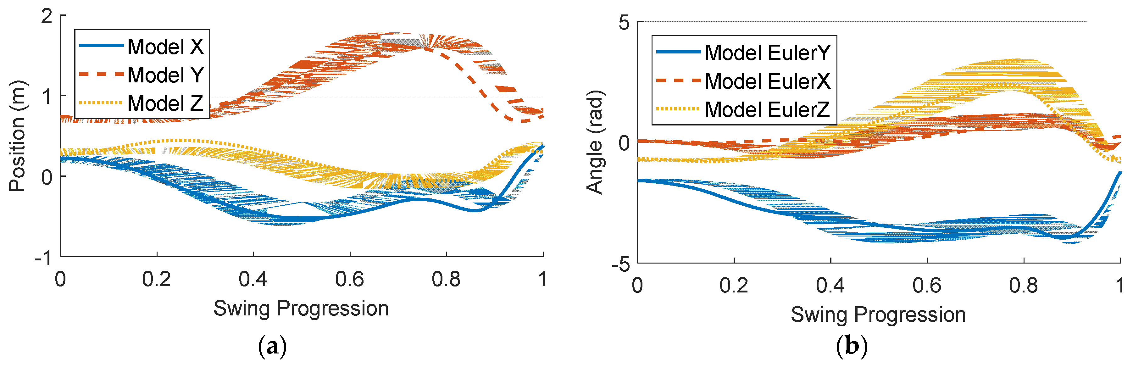
To validate the biomechanical model, the simulated grip kinematics are compared to those of elite golfers in Figure 3. The motion capture data was taken from the associated work of McNally et al. [6]. The grip orientation is defined using a Y-X-Z Euler rotations, and the kinematics are plotted against the normalized progression of the swing, from address to impact. The shaded bands represent the standard deviation of the measured kinematics for the ten elite golfers (100 golf swings total). At some points in the swing, the simulated grip kinematics fall outside the standard deviation of the experimental measurements. The discrepancies in the final quarter of the swing arise from the forward ball position that was required for the ideal clubhead delivery. It is atypical for a golfer to place the ball so far forward in the stance, but based on the results of this optimization it may be advisable to do so to create a large angle of attack and increase dynamic loft. As a result of the forward ball position, the downswing of the golfer model is effectively longer than that of a real golfer, which explains the offsets in the kinematics for the downswing portion of the swing. Despite these discrepancies, the model effectively recreated the motion of an elite golf swing with no prior knowledge of what such a swing should look like. The authenticity of the simulated golf swing lends credibility to the results of simulation experiments involving the use of this golfer model.
Acknowledgments
The authors acknowledge financial support from McPhee’s Tier I Canada Research Chair in System Dynamics, and thank PING Inc. for collecting the experimental data.
Conflicts of Interest
The authors declare no conflict of interest.
References
- Lampsa, M.A. Maximizing distance of the golf drive: An optimal control study. J. Dyn. Syst. Meas. Control 1975, 97, 362–367. [Google Scholar] [CrossRef]
- Mackenzie, S.J.; Sprigings, E.J. A three-dimensional forward dynamics model of the golf swing. Sports Eng. 2009, 11, 165–175. [Google Scholar] [CrossRef]
- Neal, R.J.; Wilson, B.D. 3D kinematics and kinetics of the golf swing. Int. J. Sport Biomech. 1985, 1, 221–232. [Google Scholar] [CrossRef]
- Sprigings, E.J.; Neal, R.J. An insight into the importance of wrist torque in driving the golfball: A simulation study. J. Appl. Biomech. 2000, 16, 356–366. [Google Scholar] [CrossRef]
- Balzerson, D.; Banerjee, J.; McPhee, J. A three-dimensional forward dynamic model of the golf swing optimized for ball carry distance. Sports Eng. 2016, 16, 237–250. [Google Scholar] [CrossRef]
- McNally, W.; McPhee, J.; Henrikson, E. The golf shaft’s influence on clubhead-ball impact dynamics. In Proceedings of the 12th Conference of the International Sports Engineering Association, Brisbane, Queensland, Australia, 26–28 March 2018. [Google Scholar]
- Myers, J.; Lephart, S.; Tsai, Y.-S.; Sell, T.; Smoliga, J.; Jolly, J. The role of upper torso and pelvis rotation in driving performance during the golf swing. J. Sports Sci. 2008, 26, 181–188. [Google Scholar] [CrossRef] [PubMed]
- Smith, A.C.; Roberts, J.R.; Wallace, E.S.; Kong, P.; Forrester, S.E. Comparison of two- and three-dimensional methods for analysis of trunk kinematic variables in the golf swing. J. Appl. Biomech. 2016, 32, 23–31. [Google Scholar] [CrossRef] [PubMed]
- De Leva, P. Adjustments to Zatsiorsky-Seluyanov’s segment inertia parameters. J. Biomech. 1996, 29, 1223–1230. [Google Scholar] [CrossRef]
- Katz, B. The relation between force and speed in muscular contraction. J. Physiol. 1939, 96, 45–64. [Google Scholar] [CrossRef]
- Van Soest, A.J.; Bobbert, M.F. The contribution of muscle properties in the control of explosive movements. Biol. Cybern. 1993, 69, 195–204. [Google Scholar] [CrossRef] [PubMed]
- Burden, A.M.; Grimshaw, P.N.; Wallace, E.S. Hip and shoulder rotations during the golf swing of sub-10 handicap players. J. Sport Sci. 1998, 16, 165–176. [Google Scholar] [CrossRef] [PubMed]
Figure 1.
Biomechanical rotational DOFs. Axes of rotation represented by dashed lines.

Figure 2.
Torque-velocity scaling for concentric and eccentric contraction.

Figure 3.
Comparison of simulated and experimental grip kinematics from elite golfers. (a) Grip position; (b) Grip orientation defined by Y-X-Z Euler rotations. The shaded bands represent one standard deviation of the measured kinematics for the ten elite golfers (100 golf swings total).
Figure 3.
Comparison of simulated and experimental grip kinematics from elite golfers. (a) Grip position; (b) Grip orientation defined by Y-X-Z Euler rotations. The shaded bands represent one standard deviation of the measured kinematics for the ten elite golfers (100 golf swings total).


Table 1.
Biomechanical optimization results.
| Variable | Lower Bound | Upper Bound | Solution | Variable | Lower Bound | Upper Bound | Solution |
|---|---|---|---|---|---|---|---|
| 0.3 | 1.2 | 0.856 | 0.8 | 1.0 | 1.000 | ||
| 1 | 0.45 | 0.55 | 0.496 | 0.8 | 1.0 | 1.000 | |
| 0.5 | 0.8 | 0.688 | 0.7 | 1.0 | 0.888 | ||
| 0.5 | 0.8 | 0.619 | 0.8 | 1.0 | 0.987 | ||
| 0.0 | 0.6 | 0.103 | 0.7 | 1.0 | 0.899 | ||
| 0.0 | 0.6 | 0.252 | 0.8 | 1.0 | 1.000 | ||
| 0.4 | 0.8 | 0.771 |
1 is the ratio of the height of the pelvis in the model to the overall height of the golfer standing upright.
Publisher’s Note: MDPI stays neutral with regard to jurisdictional claims in published maps and institutional affiliations. |
© 2018 by the authors. Licensee MDPI, Basel, Switzerland. This article is an open access article distributed under the terms and conditions of the Creative Commons Attribution (CC BY) license (https://creativecommons.org/licenses/by/4.0/).
Share and Cite
MDPI and ACS Style
McNally, W.; McPhee, J. Dynamic Optimization of the Golf Swing Using a Six Degree-of-Freedom Biomechanical Model. Proceedings 2018, 2, 243. https://doi.org/10.3390/proceedings2060243
AMA Style
McNally W, McPhee J. Dynamic Optimization of the Golf Swing Using a Six Degree-of-Freedom Biomechanical Model. Proceedings. 2018; 2(6):243. https://doi.org/10.3390/proceedings2060243
Chicago/Turabian StyleMcNally, William, and John McPhee. 2018. "Dynamic Optimization of the Golf Swing Using a Six Degree-of-Freedom Biomechanical Model" Proceedings 2, no. 6: 243. https://doi.org/10.3390/proceedings2060243